
Related Manuals for Rinnai Flametech-V2


Summary of Contents for Rinnai Flametech-V2
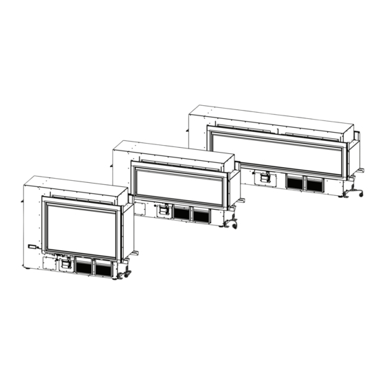
- Page 1 MODELS Flametech® - V2 (RHFE0800F) Flametech® - V2 (RHFE1000F) LS1000 - V2 (RHFE1000) LS1500 -V2 (RHFE1500) LS (V2) - Gas Fireplace Installation Manual...
- Page 2 Congratulations on the purchase of your Rinnai LS - Gas Fireplace. We trust you will have many years of comfort and enjoyment from your appliance. BEFORE INSTALLING OR USING THIS APPLIANCE Before proceeding with the operation or installation read this manual thoroughly and gain a full IMPORTANT understanding of the appliance, to ensure safe and correct installation and use.
-
Page 3: Table Of Contents
Gas Control Solenoids ..............................23 This appliance MUST be installed, maintained and removed ONLY by an Authorised Person. For continued safety of this appliance it MUST be installed and maintained in accordance with WARNING the manufacturers instructions. Rinnai RHFE0800F_1000_1500 IM... - Page 4 Wiring Diagram .................................. 36 Contacts This appliance MUST be installed, maintained and removed ONLY by an Authorised Person. For continued safety of this appliance it MUST be installed and maintained in accordance with WARNING the manufacturers instructions. Rinnai RHFE0800F_1000_1500 IM...
-
Page 5: Warnings & Important Information
For safety and warranty purposes, appliances that may be damaged or incorrect MUST NOT be installed or operated under ANY circumstances. Installation of damaged or incorrect appliances may contravene local government regulations. Rinnai disclaims any liability or responsibility whatsoever in relation to the installation or operation of damaged or incorrect appliances. -
Page 6: Modifications
WARNING: This heater MUST NOT be used if any of the glass panels are damaged. Flue terminal MUST always vent directly to outdoors. DO NOT extend the flue vertically or horizontally in ways other than prescribed in this appliance manufacturer’s installation instructions. ONLY the flue components specified by Rinnai must be used. When considering... - Page 7 Commissioning sheet (attached in a plastic pouch inside engine) Burner media - RHFE0800F/1000F ONLY (shipped inside engine) (10) Flue lock bracket and truss screws (x2) (11) Burn media - RHFE1000/1500 ONLY (packaged separately). (12) Flue components and accessory items are ordered separately. Rinnai RHFE0800F_1000_1500 IM...
-
Page 8: General Installation Information
For durability of surfaces you should contact the relevant manufacturer for their specification. RINNAI DOES NOT TAKE ANY RESPONSIBILITY FOR ANY DAMAGE OCCURRING TO ANY ITEMS INSTALLED ABOVE AND IN THE VICINITY OF THE HEATER. WARNING Use either a shelf or mantle below the TV or ornament or alternately you can construct a recess to mount TV or ornament in. -
Page 9: Framing
Plaster board is set 1 mm back from the front edge of the frame to allow for a slim edge plaster finish. To ensure correct and rattle free performance, the appliance MUST be installed on a flat level support base. Issues caused by rattling fires not installed on a flat level base, as detailed in this guide, will NOT be covered by warranty. IMPORTANT Rinnai RHFE0800F_1000_1500 IM... -
Page 10: Framing For Rhfe0800F
Fire platform shown is 18 mm Plywood 425 is minimum for single sided fire • Allow room for gas supply to enter fire cavity through base with 10 mm wallboard to maintain 50 mm clearance to back of fire. Rinnai RHFE0800F_1000_1500 IM... -
Page 11: Framing For Rhfe1000/F
425 is minimum for single sided fire • Fire platform shown is 18 mm Plywood with 10 mm wallboard to maintain • Allow room for gas supply to enter fire cavity through base 50 mm clearance to back of fire. Rinnai RHFE0800F_1000_1500 IM... -
Page 12: Framing For Rhfe1500
425 is minimum for single sided fire • Fire platform shown is 18 mm Plywood with 10 mm wallboard to maintain • Allow room for gas supply to enter fire cavity through base 50 mm clearance to back of fire. Rinnai RHFE0800F_1000_1500 IM... -
Page 13: Supply Connections
In areas where seismic activity can be expected. Secure the heater engine to the bottom of the cavity using the four seismic brackets. To level the unit and not affect where the feet go, the seismic brackets need to be elevated before the unit is installed into the cavity Rinnai RHFE0800F_1000_1500 IM... -
Page 14: Removing The Burner Box Glass
Push up the latch and slide to Glass retainer latch the side to release the glass Glass front tabs Rinnai RHFE0800F_1000_1500 IM... -
Page 15: Gas Supply
The room temperature thermistor is provided with a 1.5 metre lead and is to be positioned so that it is in the air flow of the cavity ventilation. It may be mounted directly to the inside of an air vent grill. The thermistor MUST be accessible for servicing after the wall linings have been installed. IMPORTANT Rinnai RHFE0800F_1000_1500 IM... -
Page 16: Electrical Supply
Alternatively the appliance can be direct wired to conceal the power supply. A qualified electrician will need to be consulted where a direct wired installation is required. A switch is to be provided to electrically isolate the appliance for servicing. Any such installation must comply with the requirements of AS/NZS 5601, AS/NZS 3000 and any IMPORTANT other relevant local regulations. Rinnai RHFE0800F_1000_1500 IM... -
Page 17: Flueing
(This end is supplied pre fitted to the appliance) LSFKIT01/02 (Extension piece not shown) ASPDFK Air inlet hose Flue exhaust connection Flue exhaust connection Small air inlet connection Flue exhaust Large air inlet (Rubber cap MUST remain in place) locking bracket connection Rinnai RHFE0800F_1000_1500 IM... -
Page 18: Installation Configuration Warnings
INSTALLATION CONFIGURATION WARNINGS ONLY the Rinnai flue system components specified in this reference manual MUST be used. Components NOT specified in these manuals, whether manufactured by Rinnai or otherwise, are NOT compatible and MUST NOT be used! Rinnai appliance warranty conditions may be voided if WARNING non Rinnai flue components are fitted. Use ONLY the supplied silicone grease when lubricating the O-rings. - Page 19 See Note 4. See Note 2. See Note 2. DOWN & OUT / UNDER UNDER FLOOR See Notes 1 & 3. See Note 2. See Notes 2 & 3. Cut to correct length & discard See Note 3. Rinnai RHFE0800F_1000_1500 IM...
-
Page 20: Flue Terminal Location
AS/NZ 5601 was current at the time of printing but may have been superseded. It is the installer’s responsibility to ensure that requirements of the current version of AS/NZS 5601 are met. Refer to separately supplied Rinnai LS - Gas Fireplace - Flue Installation Manual for comprehensive flue installation details. -
Page 21: Flue Components
FLUEING FLUE COMPONENTS ASPDFK2 LSFKIT01 LSFKIT02 (Direct Flue Kit for Rinnai Flamefires) (Flue Adaption Kit) (Extended Flue Adaption Kit) Internal Wall Plate Co-ax Vertical Terminal Transition Extension Pipe External Wall Plate Flue Terminal Spacer Silicon Grease Flue Transition 3x Co-ax Pipe... -
Page 22: Commissioning
L - F (Long Flue) this is the factory set default and in general will not require alteration. IMPORTANT S - F (Short Flue) refer to service manual or contact Rinnai for further details. During commissioning the plastic push buttons on the PCB are required to be pressed to make adjustments. -
Page 23: Commissioning The Pcb
3 2/3 4 1/3 4 2/3 GAS CONTROL SOLENOIDS Gas control RHFE0800F/1000/1000F Gas control RHFE1500 (additional solenoid) Inlet pressure test point screw Pilot pressure adjustment screw Pilot pressure test point screw Main burner pressure test point screw Rinnai RHFE0800F_1000_1500 IM... -
Page 24: Gas Pressures
Press the heater 'ON/OFF' button to start the ignition sequence, ensuring the correct inlet pressure is available with all other gas appliances operating on high. Press the heater 'ON/OFF' button to stop the heater operation. Disconnect the manometer hose and replace the inlet test point screw. Rinnai RHFE0800F_1000_1500 IM... -
Page 25: Setting The Pilot Pressure
MUST be set. IMPORTANT The flue length dip switch is factory set to L - F (long flue). For information regarding the S - F (short flue) setting, refer to the service manual or contact Rinnai. Remove the pilot test point screw and connect the manometer hose. Press the heater 'ON/OFF' button to start the ignition sequence, ensuring the correct inlet pressure is available with all other gas appliances operating on high. -
Page 26: Burn Media Installation
/ inadequate flue system or the artificial logs/burn media may have shifted from when the heater was first installed. There are some warning signs that could indicate a problem. If any of the signs below occur, please contact Rinnai. NORMAL FLAME PATTERN... -
Page 27: Check Wi-Fi Connectivity
If this doesn't work switch the power off and then back on again to reset the heater and retry the resetting procedure, if the issue is still unable to be resolved contact Rinnai for advice. INSTALLATION CHECKLIST & INSTALLATION RECORD It is the responsibility of the installer to complete both the "Installation Checklist"... -
Page 28: Wall Lining Installation
Below is an image to highlight the position and names of the different LS - Gas Fireplace framing components. Adjust as and where necessary, depending on the wall lining being installed. Lining support rails (adjustable/removable) Edges Finishing trim (accessory) Rinnai RHFE0800F_1000_1500 IM... -
Page 29: Plasterboard Wall With Plastered Finish
20 mm setting for Wallboard edge finished Edges combustible (not a Rinnai supplied part) Wallboard options Support Note: When fitting the Wallboard Support panels, the tabs for 10 and 13 mm boards need to be trimmed off as indicated. -
Page 30: Edge Finishing Options
1mm set back from front face of fire Finishing Trim latch A (1 : 1) Wallboard cut out A with optional Rinnai Finishing Trim Finishing Trim Cut-out size C with 3 x 8 recess Cut-out size B A (1:1) -
Page 31: Tiled Or Second Skin Wall Linings
With Wallboard Support removed the wall lining must be non-combustible Wallboard Support for at least 300 mm up wall removed. Backing board cut to clear lips and latches. Opening size C minimum Rinnai RHFE0800F_1000_1500 IM... -
Page 32: Non-Combustible Thick Wall Linings
50mm of top of heater engine Adhesive or mechanical fixing Ensure clearance around glass trim latches Wallboard Support removed Finish Trim latches will need to Opening size be allowed for if Finishing Trim C minimum is going to be used Rinnai RHFE0800F_1000_1500 IM... -
Page 33: Non-Combustible Recess Installations
(up to 100°C) or panel Any materials within this area edge finish (refer flush must be rated as non-combustible panel finishing solutions) Walls must not protrude beyond the front boundry line Opening size C minimum Front edge of lips Rinnai RHFE0800F_1000_1500 IM... -
Page 34: Specifications
Data Plate Location On the base of the combustion chamber, on left hand On the left hand side, on the convection fan access panel. side of combustion chamber base, between gas control and convection fan access panel. Rinnai RHFE0800F_1000_1500 IM... - Page 35 Above dimension are for the engine ONLY. For framing dimensions refer to section "Framing" starting on page 9. 435 min. singled sided 435 face-to-face double sided Adjustable feet on all models Glass dimensions 800 x 505 mm 1000 1000 x 280 mm 1500 1500 x 280 mm Rinnai RHFE0800F_1000_1500 IM...
-
Page 36: Wiring Diagram
OH.TH1 R.TH w bl FR2 FR1 SV 3 SV 2 SV 4 SV 1 ON/OFF BUTTON CONTROL DISPLAY UNIT WIRING DIAGRAM UNI CONTROL MODEL 2 Linear Collection 2 Burners and Combustion Fan and LED's Issue A Rinnai RHFE0800F_1000_1500 IM... - Page 37 NOTES Rinnai RHFE0800F_1000_1500 IM...
- Page 38 NOTES Rinnai RHFE0800F_1000_1500 IM...
- Page 39 NOTES Rinnai RHFE0800F_1000_1500 IM...
-
Page 40: Contacts
Tel: 1300 555 545* Fax: 1300 555 655 Monday to Friday, 8.00 am to 5.00 pm EST. *Cost of a local call may be higher from mobile phones. For further information visit www.rinnai.com.au or email enquiry@rinnai.com.au innai has a Service and Spare Parts network with...
Need help?
Do you have a question about the Flametech-V2 and is the answer not in the manual?
Questions and answers