Advertisement

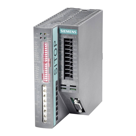
of the SITOP DC UPS Module
© Siemens AG, 2009
Considerations for Use
6A without interface
6A with serial interface
6A with USB interface
15A without interface
15A with serial interface
15A with USB interface
40A without interface
40A with USB interface
500S (15A / 2.5kWs capacitor) (6EP1933-2EC41)
500S (15A / 5kWs capacitor)
500P (15A / 5kWs capacitor)
500P (15A / 10kWs capacitor)
(6EP1931-2DC21)
(6EP1931-2DC31)
(6EP1931-2DC42)
(6EP1931-2EC21)
(6EP1931-2EC31)
(6EP1931-2EC42)
(6EP1931-2FC21)
(6EP1931-2FC42)
(6EP1933-2EC51)
(6EP1933-2NC01)
(6EP1933-2NC11)
Release 2
1/18

Advertisement

Table of Contents
loading

Summary of Contents for Siemens SITOP DC UPS 6EP1931-2DC21

  • Page 1 40A without interface (6EP1931-2FC21) 40A with USB interface (6EP1931-2FC42) 500S (15A / 2.5kWs capacitor) (6EP1933-2EC41) 500S (15A / 5kWs capacitor) (6EP1933-2EC51) 500P (15A / 5kWs capacitor) (6EP1933-2NC01) 500P (15A / 10kWs capacitor) (6EP1933-2NC11) Release 2 © Siemens AG, 2009 1/18...
  • Page 2: Table Of Contents

    5.4 Brief Power Failure in Devices with an Interface................14 6. Battery Modules ..........................15 6.1 Battery Module Selection ......................15 6.2 Discharge Characteristics for Lead-Gel Battery Modules ............16 6.3 Instructions for the Characteristic Field/Selection of the Battery Capacity.........17 © Siemens AG, 2009 2/18...
  • Page 3: Introduction

    The yellow "Bat" LED lights up and the X2.2 – X2.1 "Bat" relay contact is made. They are accordingly supplied with backup power for the buffering time set via the DIP switches or until the maximum buffering time is up (deactivation after the exhaustive discharge threshold is reached). © Siemens AG, 2009 3/18...
  • Page 4: Settings

    DIP switches (for position, see Figure 2) according to Table 1. Setting range: 22.0 to 25.5 VDC in 0.5V steps (delivery state: 22.5VDC  0.1V). Precision:  1.8% cut-in treshold [ V ] Table 1: Settable cut-in threshold [ V ] © Siemens AG, 2009 4/18...
  • Page 5: Setting The End-Of-Charge Voltage

    Switch 10 at Pos. On: Charging current 1A DC Off: Charging current 2A DC For SITOP UPS500S: Switch 10 at Pos. On: Charging current 1A DC Off: Charging current 2A DC Table 4: Setting the charging current © Siemens AG, 2009 5/18...
  • Page 6: Setting The Buffering Time

    Switch position: On = 1; Off = 0 Switch 8 at Pos. On: Disconnection of output voltage for approx. 5s Switch 8 at Pos. Off: None disconnection of the output voltage Table 7: Disconnection of output voltage © Siemens AG, 2009 6/18...
  • Page 7: Setting The On/Off Operating State

    The input voltage is lower than the set cut-in threshold. The consumers are supplied by the battery module. In buffer mode, the yellow LED (Bat) lights up and the X2.1 – X2.2 relay contact (Bat) is made (idle position in case of deactivated device). © Siemens AG, 2009 7/18...
  • Page 8: Alarm Messages

    The signals (Table 10 and Diagram 1) can be integrated into their own applications according to their content or further processed on the PC using the "SITOP DC UPS Software" freeware tool. This tool is available for download under http://www.siemens.com/sitop. 4.1 Design of Interface 4.1.1 Serial Connection...
  • Page 9: Usb Connection

    Note: If DIP Switch 8 of the lower switch panel is set to On (left), the output voltage will be disconnected for approximately 5s according to the set buffering time even if the network returns in the meantime. (This enables an automatic restart of the industrial PC). © Siemens AG, 2009 9/18...
  • Page 10: Usb Connection

    Device=VID_0403&PID_E0E4; Converter=FTD2XX for the UPS500S, 5 kWs (6EP1933-2EC51), Device=VID_0403&PID_E0E6; Converter=FTD2XX for the UPS500P, 5 kWs (6EP1933-2NC01), Device=VID_0403&PID_E0E7; Converter=FTD2XX for the UPS500P, 10 kWs (6EP1933-2NC11), The drivers and documentation can be found on the manufacturer's homepage: http://www.ftdichip.com/ © Siemens AG, 2009 10/18...
  • Page 11: Operating Modes

    (time t4) is up. DIP switch settings: Buffering according to a set time using Switch 1 On (left) Buffering time tp with Switch 2 through 7 from 5 to 635 sec. © Siemens AG, 2009 11/18...
  • Page 12: Brief Power Failure In Devices Without An Interface

    DIP switch settings: Buffering according to a set time using Switch 1 On (left) Buffering time tp with Switch 2 through 7 from 5 to 635 sec. Possible interruption of Ua using Switch 8 On (left) © Siemens AG, 2009 12/18...
  • Page 13: Long Power Failure In Devices With An Interface

    DIP switch settings: Buffering at the maximum buffering time with Switch 1 Off (right) Buffering time tp with Switch 2 through 7 from 5 to 635 sec. Possible interruption of Ua using Switch 8 On (left) © Siemens AG, 2009 13/18...
  • Page 14: Brief Power Failure In Devices With An Interface

    DIP switch settings: Buffering at the maximum buffering time with Switch 1 Off (right) Buffering time tp with Switch 2 through 7 from 5 to 635 sec. Interruption of Ua using Switch 8 On (left) © Siemens AG, 2009 14/18...
  • Page 15: Battery Modules

    Table 11: Selection table for battery modules and mains failure backup times Note: During the determination of the mains failure back times, the discharge duration of completely discharged battery modules until the battery voltage drops was based on 21V and an ambient temperature of 25°C. © Siemens AG, 2009 15/18...
  • Page 16: Discharge Characteristics For Lead-Gel Battery Modules

    0.2C means: charging current = 0.2 x battery capacity x 1/h (i.e., in case of a 12Ah battery module, 0.2C is a charging current of 0.2 x 12Ah x 1/h = 2.4A) and so on © Siemens AG, 2009 16/18...
  • Page 17: Instructions For The Characteristic Field/Selection Of The Battery Capacity

    4 hours. The point of intersection of the 21V horizontal lies above the time of 4 hours with "discharge characteristic 0.2C." Required battery capacity = 12A : 0.2 x 1/h = 60Ah; five 12Ah battery modules must thus be switched parallel. © Siemens AG, 2009 17/18...
  • Page 18 Note: The information contained in these considerations for use are only general descriptions or features that do not always apply in the concrete case of application or which may change due to the further development of the products. Subject to change. Errors and omissions excepted.  Siemens AG, 2009 Industry Sector, Industry Automation...

Table of Contents