
Related Manuals for Siemens SIRIUS 3RT


Summary of Contents for Siemens SIRIUS 3RT
- Page 1 Manual Industrial Controls Switching Devices SIRIUS - SIRIUS 3RT Contactors / Contactor assemblies Edition 09/2017 siemens.com...
- Page 3 ___________________ Introduction ___________________ Standards ___________________ Industrial Controls Safety instructions ___________________ Product description Switching devices SIRIUS - SIRIUS 3RT ___________________ Product combinations Contactors/Contactor assemblies ___________________ Configuration Manual ___________________ Mounting ___________________ Connection ___________________ Accessories ___________________ Technical data ___________________ Circuit diagrams ___________________ Types of coordination...
- Page 4 Note the following: WARNING Siemens products may only be used for the applications described in the catalog and in the relevant technical documentation. If products and components from other manufacturers are used, these must be recommended or approved by Siemens. Proper transport, storage, installation, assembly, commissioning, operation and maintenance are required to ensure that the products operate safely and without any problems.
-
Page 5: Table Of Contents
Required basic knowledge ...................... 15 Scope of the manual ....................... 15 Siemens Industry Online Support ................... 16 Further documentation ......................17 DataMatrix code ........................18 Siemens Industry Online Support app ..................18 1.10 Recycling and disposal ......................19 1.11 Technical Assistance ......................19 Standards ............................. - Page 6 Layout of application examples .................... 124 6.11.2.4 P-switching fail-safe outputs ....................125 6.11.2.5 PM-switching fail-safe outputs ..................... 132 6.12 Operation of a motor in two directions of rotation (reversing contactor assembly) ..... 140 SIRIUS - SIRIUS 3RT Contactors/Contactor assemblies Manual, 09/2017, A5E03656507120A/RS-AE/006...
- Page 7 8.2.3 Conductor cross-sections for ring cable lug connection system .......... 240 Accessories ............................243 Overview of accessories for 3RT2 contactors ..............243 9.1.1 Overview of accessories for 3RT2 contactors ..............243 SIRIUS - SIRIUS 3RT Contactors/Contactor assemblies Manual, 09/2017, A5E03656507120A/RS-AE/006...
- Page 8 LED display indicator module ....................338 9.11.1 Description ........................... 338 9.11.2 Mounting ..........................339 9.12 Solder pin adapter ........................ 340 9.12.1 Description ........................... 340 9.12.2 Mounting ..........................341 9.13 Coil terminal module ......................343 SIRIUS - SIRIUS 3RT Contactors/Contactor assemblies Manual, 09/2017, A5E03656507120A/RS-AE/006...
- Page 9 Mounting size S2 ........................376 9.26.5 Mounting size S3 ........................380 9.27 Wiring kit for reversing contactor assemblies (sizes S6 to S12) .......... 385 9.27.1 Description ..........................385 9.27.2 Mounting size S6 ........................386 SIRIUS - SIRIUS 3RT Contactors/Contactor assemblies Manual, 09/2017, A5E03656507120A/RS-AE/006...
- Page 10 Description ........................... 456 9.34.2 Configuration ........................459 9.34.3 Mounting/Disassembly ......................459 Technical data ............................. 461 10.1 Technical data in Siemens Industry Online Support ............461 10.2 Overview tables........................461 Circuit diagrams ........................... 463 11.1 CAx data ..........................463 11.2 Contactors and contactor accessories ................. 464 11.3...
- Page 11 3RA244 contactor assemblies for star-delta (wye-delta) start (size S3) ......545 C.11.4.1 3RA244.-8X.32-1 contactor assemblies for star-delta (wye-delta) start (size S3) ....545 C.11.4.2 Drilling diagram for 3RA244.-8X.32-1 contactor assemblies for star-delta (wye-delta) start (size S3) ........................546 Index..............................547 SIRIUS - SIRIUS 3RT Contactors/Contactor assemblies Manual, 09/2017, A5E03656507120A/RS-AE/006...
- Page 12 Table of contents SIRIUS - SIRIUS 3RT Contactors/Contactor assemblies Manual, 09/2017, A5E03656507120A/RS-AE/006...
-
Page 13: Introduction
Nor can Siemens assume liability for recommendations that appear or are implied in the following description. No new guarantee, warranty, or liability claims beyond the scope of the Siemens general terms of supply are to be derived or inferred from the following description. Note When designing a system, comply with all valid national installation specifications and standards. -
Page 14: Purpose Of The Manual
● Information about installing and connecting the contactors. ● Technical information such as dimension drawings and unit wiring diagrams. The information in this manual enables you to configure and commission the contactors. SIRIUS - SIRIUS 3RT Contactors/Contactor assemblies Manual, 09/2017, A5E03656507120A/RS-AE/006... -
Page 15: Advantages Through Energy Efficiency
1.3 Advantages through energy efficiency Advantages through energy efficiency Siemens offers you a unique portfolio for efficient energy management in industry – a process that serves to optimally shape your energy requirement. Operational energy management is subdivided into three phases: ●... -
Page 16: Siemens Industry Online Support
Siemens Industry Online Support Information and Service In Siemens Industry Online Support, you can obtain up-to-date information from our global support database quickly and simply. To accompany our products and systems, we offer a wealth of information and services that provide support in every phase of the lifecycle of your machine or plant –... -
Page 17: Further Documentation
You can find a list of operating instructions and an overview of the manuals pertaining to the SIRIUS modular system in the Appendix "References (Page 495)". SIRIUS - SIRIUS 3RT Contactors/Contactor assemblies Manual, 09/2017, A5E03656507120A/RS-AE/006... -
Page 18: Datamatrix Code
Siemens Industry Online Support app Siemens Industry Online Support app You can use the Siemens Industry Online Support app to access all the device-specific information available on the Siemens Industry Online Support portal for a particular article number, including operating instructions, manuals, datasheets, FAQs etc. -
Page 19: Recycling And Disposal
You can obtain further assistance by calling the following numbers: Technical Assistance: Telephone: +49 (911) 895-5900 (8 a.m. to 5 p.m. CET) Fax: +49 (911) 895-5907 or on the Internet at: E-mail: (mailto:technical-assistance@siemens.com) Internet: (http://www.siemens.com/sirius/technical-assistance) SIRIUS - SIRIUS 3RT Contactors/Contactor assemblies Manual, 09/2017, A5E03656507120A/RS-AE/006... - Page 20 Introduction 1.11 Technical Assistance SIRIUS - SIRIUS 3RT Contactors/Contactor assemblies Manual, 09/2017, A5E03656507120A/RS-AE/006...
-
Page 21: Standards
- Part 1: General principles for design IEC 61508 Functional safety of electrical/electronic/programmable electronic safety-related systems IEC 62061 Safety of machinery - Functional safety of safety-related electrical, electronic and programmable electronic control systems SIRIUS - SIRIUS 3RT Contactors/Contactor assemblies Manual, 09/2017, A5E03656507120A/RS-AE/006... - Page 22 (shipbuilding, etc.). More information and certificates for download are available on the Internet (https://support.industry.siemens.com/cs/ww/en/ps/16131/cert). Reference You can find all the technical data and other information regarding the products in the Siemens Industry Online Support (https://support.industry.siemens.com/cs/ww/en/ps/16132/td). SIRIUS - SIRIUS 3RT Contactors/Contactor assemblies Manual, 09/2017, A5E03656507120A/RS-AE/006...
-
Page 23: Protective Separation
The insulation must be resistant to aging for the duration of the expected service life. Circuits without a safety extra low voltage or a functional extra low voltage do not require protective separation. SIRIUS - SIRIUS 3RT Contactors/Contactor assemblies Manual, 09/2017, A5E03656507120A/RS-AE/006... -
Page 24: Positively Driven Contact Elements/Mirror Contacts
The 3RT1 / 3RT2 / 3RH2 contactors are suitable for applications in the safety circuit. For contactor relays, this applies on account of the positively driven operation of the contacts. For motor contactors, it applies on account of the mirror contact properties of the auxiliary contacts. SIRIUS - SIRIUS 3RT Contactors/Contactor assemblies Manual, 09/2017, A5E03656507120A/RS-AE/006... -
Page 25: Used For Stop Category 0 / 1
All SIRIUS 3RT1, 3RT2 and 3RH2 contactors with mirror contacts / positively driven contacts are generally suitable for use in safety circuits according to stop category 0 / stop category 1. SIRIUS - SIRIUS 3RT Contactors/Contactor assemblies Manual, 09/2017, A5E03656507120A/RS-AE/006... -
Page 26: Ie3 / Ie4 Ready
For the use of 3RT contactors in conjunction with highly energy-efficient IE3 / IE4 motors, please observe the information on dimensioning and configuring in the "Application Manual - SIRIUS Controls with IE3 / IE4 Motors (https://support.industry.siemens.com/cs/ww/en/view/94770820)". SIRIUS - SIRIUS 3RT Contactors/Contactor assemblies Manual, 09/2017, A5E03656507120A/RS-AE/006... -
Page 27: Applications
The different contactor series with their possible application areas are explained in the following subsections. SIRIUS - SIRIUS 3RT Contactors/Contactor assemblies Manual, 09/2017, A5E03656507120A/RS-AE/006... - Page 28 Control of electromagnetic loads (over 72 VA) Auxiliary circuit contacts: Utilization category for DC voltages DC-12 Control of resistive loads and solid-state loads with isolation by opto couplers DC-13 Control of electromagnets SIRIUS - SIRIUS 3RT Contactors/Contactor assemblies Manual, 09/2017, A5E03656507120A/RS-AE/006...
-
Page 29: Safety Instructions
The 3RT / 3RH contactors with electronic operating mechanism have been designed for Environment A. Use of these products in Environment B may cause unwanted electromagnetic disturbances in which case the user may be required to take adequate mitigation measures. SIRIUS - SIRIUS 3RT Contactors/Contactor assemblies Manual, 09/2017, A5E03656507120A/RS-AE/006... -
Page 30: Intended Use
Use of hardware products for intended purpose This equipment is only allowed to be used for the applications described in the catalog and in the technical description, and only in conjunction with non-Siemens equipment and components recommended by Siemens. Correct transport, storage, installation and assembly, as well as careful operation and maintenance, are required to ensure that the product operates safely and without faults. -
Page 31: Product Description
S00 to S12 (table contains versions featuring screw- type connection system). Size 3RH2 contactor 3RT2 power contactors 3RA23 reversing contactor 3RA24 contactor assembly for relays assembly star-delta (wye-delta) start SIRIUS - SIRIUS 3RT Contactors/Contactor assemblies Manual, 09/2017, A5E03656507120A/RS-AE/006... - Page 32 Product description 4.1 Overview of the contactor range Size 3RH2 contactor 3RT2 power contactors 3RA23 reversing contactor 3RA24 contactor assembly for relays assembly star-delta (wye-delta) start SIRIUS - SIRIUS 3RT Contactors/Contactor assemblies Manual, 09/2017, A5E03656507120A/RS-AE/006...
- Page 33 Product description 4.1 Overview of the contactor range Size 3RT10 power contactors S10 / S12 Size 3RT12 vacuum contactors S10 / S12 SIRIUS - SIRIUS 3RT Contactors/Contactor assemblies Manual, 09/2017, A5E03656507120A/RS-AE/006...
- Page 34 Reversing contactor assembly (for self-assembly), size S6, as an example S6 / S10 / S12 Size Contactor assembly for star-delta (wye-delta) start (for self-assembly), size S6, as an example S6 / S10 / S12 SIRIUS - SIRIUS 3RT Contactors/Contactor assemblies Manual, 09/2017, A5E03656507120A/RS-AE/006...
-
Page 35: Device Versions
Several standard motor ratings are available for each size. Reference More information ... Can be found in the chapter titled ... About the basic and special versions of the Configuration (Page 67) contactor relays and power contactors SIRIUS - SIRIUS 3RT Contactors/Contactor assemblies Manual, 09/2017, A5E03656507120A/RS-AE/006... -
Page 36: 3Rt2 Power Contactors
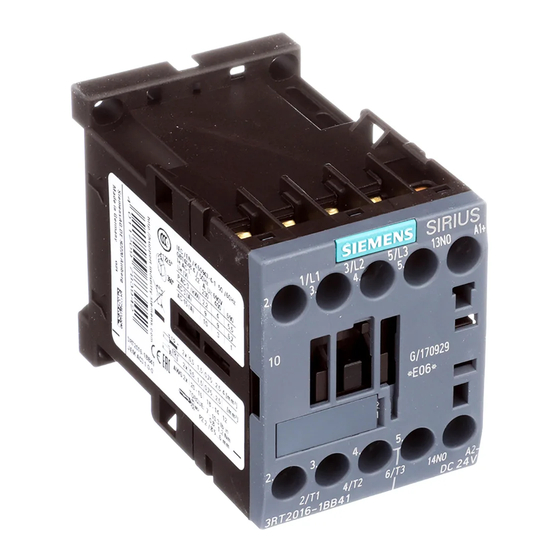
● Busbar connection (size S3 only) ● Box terminal connection (size S3 only) ● Solder pin connection (size S00 only) Solder pin connection is only possible in conjunction with the optional solder pin adapter accessory SIRIUS - SIRIUS 3RT Contactors/Contactor assemblies Manual, 09/2017, A5E03656507120A/RS-AE/006... - Page 37 Contactor's main circuit terminal to the load / motor connection (T1, T2, T3) ⑧ Contactor's main circuit terminal to the power network (L1, L2, L3) Figure 4-1 3RT201.-..-..power contactor, size S00, overview SIRIUS - SIRIUS 3RT Contactors/Contactor assemblies Manual, 09/2017, A5E03656507120A/RS-AE/006...
- Page 38 2 auxiliary contacts integrated (1 NO contact and 1 NC contact) ⑨ Contactor's main circuit terminal to the power network (L1, L2, L3) Figure 4-2 3RT202.-..-..power contactor, size S0, overview SIRIUS - SIRIUS 3RT Contactors/Contactor assemblies Manual, 09/2017, A5E03656507120A/RS-AE/006...
- Page 39 2 auxiliary contacts integrated (1 NO contact and 1 NC contact) ⑨ Contactor's main circuit terminal to the power network (L1, L2, L3) Figure 4-3 3RT203.-..-..power contactor, size S2, overview SIRIUS - SIRIUS 3RT Contactors/Contactor assemblies Manual, 09/2017, A5E03656507120A/RS-AE/006...
- Page 40 Removable main circuit terminal of the contactor to the power network (L1, L2, L3). A ring cable lug connection or a busbar connection is optionally possible following removal of the box terminal block. Figure 4-4 3RT204.-..-..power contactor, size S3, overview (example illustration) SIRIUS - SIRIUS 3RT Contactors/Contactor assemblies Manual, 09/2017, A5E03656507120A/RS-AE/006...
-
Page 41: 3Rt10 / 3Rt14 Power Contactors And 3Rt12 Vacuum Contactors
Up to four NC contacts are permissible. Connection systems The contactors can be supplied with the connection systems detailed below: ● Screw connection ● Spring-loaded connection ● Bus connection ● Box terminal connection SIRIUS - SIRIUS 3RT Contactors/Contactor assemblies Manual, 09/2017, A5E03656507120A/RS-AE/006... - Page 42 4 laterally mounted auxiliary contacts (2 NO contacts and 2 NC contacts) ⑦ Main circuit connection as busbar connection (L1, L2, L3) Figure 4-5 3RT1054-6NB36 power contactor, size S6, overview (example illustration) SIRIUS - SIRIUS 3RT Contactors/Contactor assemblies Manual, 09/2017, A5E03656507120A/RS-AE/006...
- Page 43 4 laterally mounted auxiliary contacts (2 NO contacts and 2 NC contacts) ⑦ Main circuit connection as busbar connection (L1, L2, L3) Figure 4-6 3RT1064-6AB36 power contactor, size S10, overview (example illustration) SIRIUS - SIRIUS 3RT Contactors/Contactor assemblies Manual, 09/2017, A5E03656507120A/RS-AE/006...
- Page 44 4 laterally mounted auxiliary contacts (2 NO contacts and 2 NC contacts) ⑦ Main circuit connection as busbar connection (L1, L2, L3) Figure 4-7 3RT1075-6NB36 power contactor, size S12, overview (example illustration) SIRIUS - SIRIUS 3RT Contactors/Contactor assemblies Manual, 09/2017, A5E03656507120A/RS-AE/006...
- Page 45 ⑤ 4 laterally mounted auxiliary contacts (2 NO contacts and 2 NC contacts) ⑥ Main circuit connection as busbar connection (L1, L2, L3) Figure 4-8 3RT1264-6LA06 vacuum contactor, size S10, overview SIRIUS - SIRIUS 3RT Contactors/Contactor assemblies Manual, 09/2017, A5E03656507120A/RS-AE/006...
- Page 46 ⑤ 4 laterally mounted auxiliary contacts (2 NO contacts and 2 NC contacts) ⑥ Main circuit connection as busbar connection (L1, L2, L3) Figure 4-9 3RT1275-6LA06 vacuum contactor, size S12, overview SIRIUS - SIRIUS 3RT Contactors/Contactor assemblies Manual, 09/2017, A5E03656507120A/RS-AE/006...
-
Page 47: 3Rh2 Contactor Relays
Screw connection ✓ ✓ ✓ Spring-loaded connection ✓ ✓ ✓ Ring cable lug connection ✓ Solder pin connection (only ✓ ✓ ✓ possible in conjunction with the "solder pin adapter" optional accessory) SIRIUS - SIRIUS 3RT Contactors/Contactor assemblies Manual, 09/2017, A5E03656507120A/RS-AE/006... - Page 48 ② Location hole for surge suppression ③ Location hole for 1-, 2-, and 4-pole auxiliary switch blocks ④ Label ⑤ Auxiliary contacts Figure 4-10 3RH21..-..contactor relay, 4-pole, size S00, overview SIRIUS - SIRIUS 3RT Contactors/Contactor assemblies Manual, 09/2017, A5E03656507120A/RS-AE/006...
- Page 49 ② Location hole for surge suppression ③ Label ④ Auxiliary contacts Figure 4-11 3RH22..-..contactor relay with auxiliary switch block on the front which cannot be removed, 8-pole, size S00, overview SIRIUS - SIRIUS 3RT Contactors/Contactor assemblies Manual, 09/2017, A5E03656507120A/RS-AE/006...
-
Page 50: 3Rt26 Capacitor Contactors
2 NC contacts or 1 NO contact and 1 NC contact Versions of the 3RT26 capacitor contactors Connection systems The capacitor contactors can be supplied with the connection systems detailed below: ● Screw connection SIRIUS - SIRIUS 3RT Contactors/Contactor assemblies Manual, 09/2017, A5E03656507120A/RS-AE/006... - Page 51 Contactor's main circuit terminal to the load (T1, T2, T3) ⑦ Label ⑧ Contactor's main circuit terminal to the power network (L1, L2, L3) Figure 4-12 3RT2617.-..-..capacitor contactor, size S00, overview SIRIUS - SIRIUS 3RT Contactors/Contactor assemblies Manual, 09/2017, A5E03656507120A/RS-AE/006...
- Page 52 Contactor's main circuit terminal to the load (T1, T2, T3) ⑥ Precharging resistors ⑦ Label ⑧ 2 integrated auxiliary contacts ⑨ Contactor's main circuit terminal to the power network (L1, L2, L3) Figure 4-13 3RT2625-..-..capacitor contactor, size S0, overview SIRIUS - SIRIUS 3RT Contactors/Contactor assemblies Manual, 09/2017, A5E03656507120A/RS-AE/006...
- Page 53 Contactor's main circuit terminal to the load (T1, T2, T3) ⑦ Precharging resistors ⑧ Label ⑨ 2 integrated auxiliary contacts ⑩ Contactor's main circuit terminal to the power network (L1, L2, L3) Figure 4-14 3RT2628-..-..capacitor contactor, size S0, overview SIRIUS - SIRIUS 3RT Contactors/Contactor assemblies Manual, 09/2017, A5E03656507120A/RS-AE/006...
- Page 54 Contactor's main circuit terminal to the load (T1, T2, T3) ⑥ Lateral auxiliary switch, left, with 2 auxiliary contacts ⑦ Contactor's main circuit terminal to the power network (L1, L2, L3) Figure 4-15 3RT263.-..-..capacitor contactor, size S2, overview SIRIUS - SIRIUS 3RT Contactors/Contactor assemblies Manual, 09/2017, A5E03656507120A/RS-AE/006...
- Page 55 Location hole for surge suppression ⑤ Label ⑥ Contactor's main circuit terminal to the load (T1, T2, T3) ⑦ Lateral auxiliary switch, left, with 2 auxiliary contacts Figure 4-16 3RT264.-..-..capacitor contactor, size S3, overview SIRIUS - SIRIUS 3RT Contactors/Contactor assemblies Manual, 09/2017, A5E03656507120A/RS-AE/006...
-
Page 56: 3Ra23 Reversing Contactor Assemblies
The illustrations below show the fully assembled reversing contactor assemblies, in the version with the screw-type connection system. 3RA23 reversing contactor assembly, screw connection, size S00 3RA23 reversing contactor assembly, screw connection, size S0 SIRIUS - SIRIUS 3RT Contactors/Contactor assemblies Manual, 09/2017, A5E03656507120A/RS-AE/006... - Page 57 Product description 4.2 Device versions 3RA23 reversing contactor assembly, screw connection, size S2 3RA23 reversing contactor assembly, screw connection, size S3 SIRIUS - SIRIUS 3RT Contactors/Contactor assemblies Manual, 09/2017, A5E03656507120A/RS-AE/006...
- Page 58 (Page 385). About the function modules that can be attached 3RA27 function modules for connection to the to a reversing contactor assembly with controller (AS-Interface or IO-Link). (Page 363) communication interface SIRIUS - SIRIUS 3RT Contactors/Contactor assemblies Manual, 09/2017, A5E03656507120A/RS-AE/006...
-
Page 59: 3Ra24 Contactor Assemblies For Star-Delta (Wye-Delta) Start
The illustrations below show the fully assembled contactor assembly for star-delta (wye- delta) start without a communication connection, in the version with the screw-type connection system. 3RA24 contactor assembly for star-delta (wye-delta) start, screw connection, size S00 SIRIUS - SIRIUS 3RT Contactors/Contactor assemblies Manual, 09/2017, A5E03656507120A/RS-AE/006... - Page 60 4.2 Device versions 3RA24 contactor assembly for star-delta (wye-delta) start, screw connection, size S0 3RA24 contactor assembly for star-delta (wye-delta) start, screw connection, size S2 / S2 / 3RA2434-8X.32-1... 3RA2435-8X.32-1... 3RA2436-8X.32-1... SIRIUS - SIRIUS 3RT Contactors/Contactor assemblies Manual, 09/2017, A5E03656507120A/RS-AE/006...
- Page 61 4.2 Device versions 3RA24 contactor assembly for star-delta (wye-delta) start, screw connection, size S2 / S2 / 3RA2437-8X.32-1... 3RA24 contactor assembly for star-delta (wye-delta) start, screw connection, size S3 / S3 / SIRIUS - SIRIUS 3RT Contactors/Contactor assemblies Manual, 09/2017, A5E03656507120A/RS-AE/006...
- Page 62 (wye-delta) start (sizes S00 to S3) (wye-delta) start (Page 391) and Wiring kit for contactor assemblies for star-delta (wye-delta) start (sizes S6 to S12). (Page 427). SIRIUS - SIRIUS 3RT Contactors/Contactor assemblies Manual, 09/2017, A5E03656507120A/RS-AE/006...
-
Page 63: Drive Options
– For contactors with extended operating range (e.g. for railway applications) for PLC output 24 ... 110 V DC Reference Reference More information ... Can be found in the chapter titled ... About contactor relay and power contactor Configuration (Page 67) applications SIRIUS - SIRIUS 3RT Contactors/Contactor assemblies Manual, 09/2017, A5E03656507120A/RS-AE/006... - Page 64 Product description 4.3 Reference SIRIUS - SIRIUS 3RT Contactors/Contactor assemblies Manual, 09/2017, A5E03656507120A/RS-AE/006...
-
Page 65: Product Combinations
More information ... Can be found in the appendix ... About the possible combinations of standard "References" under "Manuals - SIRIUS Modular products from the SIRIUS modular system System (Page 497)" SIRIUS - SIRIUS 3RT Contactors/Contactor assemblies Manual, 09/2017, A5E03656507120A/RS-AE/006... - Page 66 Product combinations SIRIUS - SIRIUS 3RT Contactors/Contactor assemblies Manual, 09/2017, A5E03656507120A/RS-AE/006...
-
Page 67: Configuration
AC-12/AC-15/AC-14/DC-12/DC-13). 3RH21 4-pole contactor relays • 3RH22 8-pole contactor relays • Switching of capacitive Contactors for switching capacitive loads (utilization category AC-6b) loads 3RT26 3-pole capacitor contactors • SIRIUS - SIRIUS 3RT Contactors/Contactor assemblies Manual, 09/2017, A5E03656507120A/RS-AE/006... -
Page 68: Sirius System Configurator
Internet. Here, you can gather together all necessary products before the actual configuration process and you can realize complete projects virtually. You can find the "SIRIUS system configurator" on the Internet (http://www.siemens.com/sirius/configurators). SIRIUS - SIRIUS 3RT Contactors/Contactor assemblies Manual, 09/2017, A5E03656507120A/RS-AE/006... -
Page 69: Operating Mechanism System / Coil Selection 3Rt Contactors And 3Rh2 Contactor Relays
175 to 280 V • • For further details, refer to the chapter titled "Technical data". At 280 V: high limit = 1.1 x U Additional voltage versions are available on request. SIRIUS - SIRIUS 3RT Contactors/Contactor assemblies Manual, 09/2017, A5E03656507120A/RS-AE/006... -
Page 70: Operating Mechanism System / Coil Selection 3Rt1 Contactors
To the extent that especially fault-prone applications make further attenuation measures necessary, RC elements (accessories) can be additionally attached. Note No additional RC elements can be mounted on the solid-state operating mechanisms for standard contactors with remaining lifetime signal RLT. SIRIUS - SIRIUS 3RT Contactors/Contactor assemblies Manual, 09/2017, A5E03656507120A/RS-AE/006... - Page 71 ③ Withdrawable coil for contactors with remaining lifetime signal RLT and associated electronic module ④ Withdrawable coil "solid-state operating mechanism" ⑤ Withdrawable coil "conventional operating mechanism" ⑥ Surge suppressor (RC element) SIRIUS - SIRIUS 3RT Contactors/Contactor assemblies Manual, 09/2017, A5E03656507120A/RS-AE/006...
-
Page 72: Conventional Operating Mechanism
Operating range The operating range is 0.8 x U - 1.1 x U , for the example, this means: 0.8 x 220 V - s min s max 1.1 x 240 V. SIRIUS - SIRIUS 3RT Contactors/Contactor assemblies Manual, 09/2017, A5E03656507120A/RS-AE/006... -
Page 73: Solid-State Operating Mechanism For Standard Contactors
The hysteresis in the switching thresholds prevents the main contacts from chattering and thus prevents increased wear or welding when operated in weak, unstable networks. The ON threshold prevents thermal overload of the coil if an excessively low control supply voltage is applied. SIRIUS - SIRIUS 3RT Contactors/Contactor assemblies Manual, 09/2017, A5E03656507120A/RS-AE/006... - Page 74 For 24 V DC PLC output 3RT10 / 14 air-break contactors, 3RT12 vacuum contactors 3RT1...-.P For 24 V DC PLC output or PLC relay output; 3RT10 / 14 air-break contactors with remaining lifetime signal RLT SIRIUS - SIRIUS 3RT Contactors/Contactor assemblies Manual, 09/2017, A5E03656507120A/RS-AE/006...
- Page 75 The contactor can be operated direct via an output of a controller (PLC). ● Rated voltage 24 V DC, operating range 17 to 30 V ● Current consumption ≤ 30 mA SIRIUS - SIRIUS 3RT Contactors/Contactor assemblies Manual, 09/2017, A5E03656507120A/RS-AE/006...
- Page 76 The control signal is connected via a 2-pin plug-in connection on the front side of the withdrawable coil (the spring-loaded connector is included in the scope of supply). The connector is labeled with the polarity. SIRIUS - SIRIUS 3RT Contactors/Contactor assemblies Manual, 09/2017, A5E03656507120A/RS-AE/006...
-
Page 77: Solid-State Operating Mechanism For Standard Contactors With Remaining Lifetime Signal Rlt
The different contact erosion states are also indicated visually on the laterally mounted electronic module of the contactor via LEDs: ● 60 % with remaining lifetime (green LED) ● 40 % (orange) ● 20 % (red) SIRIUS - SIRIUS 3RT Contactors/Contactor assemblies Manual, 09/2017, A5E03656507120A/RS-AE/006... - Page 78 However, depending on slip, voltage values arise in the rotor circuits that are not suitable for evaluation and that result in premature signaling of RLT. SIRIUS - SIRIUS 3RT Contactors/Contactor assemblies Manual, 09/2017, A5E03656507120A/RS-AE/006...
- Page 79 The cables connected on the input and output sides of the main current paths are for detecting the remaining lifetime signal RLT. SIRIUS - SIRIUS 3RT Contactors/Contactor assemblies Manual, 09/2017, A5E03656507120A/RS-AE/006...
- Page 80 Automatic control can be changed over to local control via inputs H1/H2. During commissioning or in the event of a fault, for example, automatic control via PLC or SIMOCODE can be deactivated and the contactor can be controlled manually. SIRIUS - SIRIUS 3RT Contactors/Contactor assemblies Manual, 09/2017, A5E03656507120A/RS-AE/006...
- Page 81 Electronic module for 3RT1...-.P contactor ② Plug-in connection, 7-pin ③ ④ Remaining lifetime signal 20 % ⑤ PLC output Changeover switch from automatic control via PLC semiconductor output to local control Local control option SIRIUS - SIRIUS 3RT Contactors/Contactor assemblies Manual, 09/2017, A5E03656507120A/RS-AE/006...
- Page 82 Electronic module for 3RT1...-.P contactor ② Plug-in connection, 7-pin ③ ④ Remaining lifetime signal 20 % Changeover switch from automatic control, e.g. via SIMOCODE or PLC relay output, to local control Local control option SIRIUS - SIRIUS 3RT Contactors/Contactor assemblies Manual, 09/2017, A5E03656507120A/RS-AE/006...
-
Page 83: Solid-State Operating Mechanism For Contactors With Extended Operating Range And Rail Applications
The supply voltage for the solenoid operating mechanism must be connected to A1/A2. Note The slide switch on the front side of the withdrawable coil must be switched to the "ON" position before commissioning (factory default setting is "OFF"). SIRIUS - SIRIUS 3RT Contactors/Contactor assemblies Manual, 09/2017, A5E03656507120A/RS-AE/006... - Page 84 The control signal is connected via a 2-pin plug-in connection on the front side of the withdrawable coil (the spring-loaded connector is included in the scope of supply). The connector is labeled with the polarity. SIRIUS - SIRIUS 3RT Contactors/Contactor assemblies Manual, 09/2017, A5E03656507120A/RS-AE/006...
-
Page 85: Solid-State Operating Mechanism For Contactors With Fail-Safe Control Input
● Current consumption ≤ 15 mA ● Digital control input type 1 (IEC 60947-1, Annex S) Connecting the supply voltage The supply voltage for the solenoid operating mechanism must be connected to A1/A2. SIRIUS - SIRIUS 3RT Contactors/Contactor assemblies Manual, 09/2017, A5E03656507120A/RS-AE/006... - Page 86 The control signal is connected via a 2-pin plug-in connection on the front side of the withdrawable coil (the spring-loaded connector is included in the scope of supply). The connector is labeled with the polarity. SIRIUS - SIRIUS 3RT Contactors/Contactor assemblies Manual, 09/2017, A5E03656507120A/RS-AE/006...
-
Page 87: Typical Circuit Diagrams (Standard Contactors)
The following typical circuit diagrams apply to the 3RT1 standard contactors. Note You will find application examples of contactors with fail-safe control input in the chapter entitled "Contactors in safety applications (Page 118)". Contactor assembly with 24 V DC PLC control SIRIUS - SIRIUS 3RT Contactors/Contactor assemblies Manual, 09/2017, A5E03656507120A/RS-AE/006... - Page 88 • The H2 terminals should not be bridged since otherwise the internal connection from A1 to H2 will be overloaded in the event of a fault. Control via relay outputs with common potential Local control via SIMOCODE Control via galvanically isolated / floating relay outputs SIRIUS - SIRIUS 3RT Contactors/Contactor assemblies Manual, 09/2017, A5E03656507120A/RS-AE/006...
-
Page 89: Application Environment
The 3RH2 contactor relays are dimensioned for operation at ambient temperatures of between -25 °C and +60 °C. The devices can be stored at temperatures within the range from -55 °C to +80 °C. SIRIUS - SIRIUS 3RT Contactors/Contactor assemblies Manual, 09/2017, A5E03656507120A/RS-AE/006... -
Page 90: 3Rt Power Contactors
/AC-1 or I /DC-1 = Rated operational current of the contactor for respective utilization category and T ≤ 60 °C Actual ambient temperature T > 60 °C SIRIUS - SIRIUS 3RT Contactors/Contactor assemblies Manual, 09/2017, A5E03656507120A/RS-AE/006... - Page 91 (in the case of a transistor: short-circuit). A microcontroller in the circuit measures the chip temperature and switches the device off if it is too high. SIRIUS - SIRIUS 3RT Contactors/Contactor assemblies Manual, 09/2017, A5E03656507120A/RS-AE/006...
- Page 92 [x10 operating cycles] [years] S0 … S3 S00 … S3 ≤ 60 °C 65 °C 70 °C The specifications for the service life apply to an ON period of 100 %. SIRIUS - SIRIUS 3RT Contactors/Contactor assemblies Manual, 09/2017, A5E03656507120A/RS-AE/006...
-
Page 93: Contactors For Railway Applications
An important railway requirement as regards SIRIUS contactors is the extended operating range of the solenoid coil (0.7 ... 1.25 x U ). This must be taken into account when selecting devices for railway applications. SIRIUS - SIRIUS 3RT Contactors/Contactor assemblies Manual, 09/2017, A5E03656507120A/RS-AE/006... -
Page 94: Installation Altitude
For plants at higher altitudes, the reduced insulation strength and the reduced cooling effect of the air must be taken into consideration. For electrical devices that are to operate under such conditions, the design and application must be agreed between manufacturer and user. SIRIUS - SIRIUS 3RT Contactors/Contactor assemblies Manual, 09/2017, A5E03656507120A/RS-AE/006... -
Page 95: Switching Motorized Loads
3RT12 vacuum contactors are fundamentally unsuitable for switching DC voltage. The following graphic shows the cross-section of a vacuum interrupter. ① Fixed contact ② Contacts ③ Arc chute ④ Ceramic insulator ⑤ Metal bellows ⑥ Locating bearing ⑦ Movable contact SIRIUS - SIRIUS 3RT Contactors/Contactor assemblies Manual, 09/2017, A5E03656507120A/RS-AE/006... - Page 96 The performance range of 55 to 250 kW / 400 V (utilization category AC-2, AC-3 and AC-4) is covered by the 3RT1 contactors (sizes S6 to S12) with a width of 120 mm to 160 mm. SIRIUS - SIRIUS 3RT Contactors/Contactor assemblies Manual, 09/2017, A5E03656507120A/RS-AE/006...
- Page 97 P/AC-3/400 [kW] /AC-3 [A] to 400 V Width [mm] (size S2) 3RT2035 18.5 3RT2036 3RT2037 3RT2038 Article number P/AC-3/400 [kW] /AC-3 [A] to 400 V Width [mm] (size S3) 3RT2045 3RT2046 3RT2047 SIRIUS - SIRIUS 3RT Contactors/Contactor assemblies Manual, 09/2017, A5E03656507120A/RS-AE/006...
- Page 98 Article number P/AC-4/400 [kW] /AC-3 [A] to 1000 V Width [mm] (size S10) 3RT1264 3RT1265 3RT1266 Article number P/AC-4/400 [kW] /AC-3 [A] to 1000 V Width [mm] (size S12) 3RT1275 3RT1276 SIRIUS - SIRIUS 3RT Contactors/Contactor assemblies Manual, 09/2017, A5E03656507120A/RS-AE/006...
- Page 99 The main current path attenuation module is connected separately from the contactor over a cable of a length of approximately 35 cm on the outgoing terminal of the 2T1 / 4T2 / 6T3 contactor. SIRIUS - SIRIUS 3RT Contactors/Contactor assemblies Manual, 09/2017, A5E03656507120A/RS-AE/006...
-
Page 100: Switching Resistive Loads
DC solenoid system is 10 mm larger than that for versions with an AC solenoid system. Within the respective size (S2 to S12) all operating mechanism types have the same installation depth. SIRIUS - SIRIUS 3RT Contactors/Contactor assemblies Manual, 09/2017, A5E03656507120A/RS-AE/006... - Page 101 3RT2027 3RT2028 Article number /AC-1 [A] to 690 V Width [mm] (size S2) 3RT2035 3RT2036 3RT2037 3RT2038 Article number /AC-1 [A] to 690 V Width [mm] (size S3) 3RT2045 3RT2046 3RT2047 SIRIUS - SIRIUS 3RT Contactors/Contactor assemblies Manual, 09/2017, A5E03656507120A/RS-AE/006...
- Page 102 /AC-1 [A] to 690 V Width [mm] (size S6) 3RT1456 Article number /AC-1 [A] to 690 V Width [mm] (size S10) 3RT1466 Article number /AC-1 [A] to 690 V Width [mm] (size S12) 3RT1476 SIRIUS - SIRIUS 3RT Contactors/Contactor assemblies Manual, 09/2017, A5E03656507120A/RS-AE/006...
-
Page 103: Changing The Polarity Of Hoisting Gear Motors
DC solenoid system is 10 mm larger than that for versions with an AC solenoid system. In the case of sizes S2 and S3, all operating mechanism types have the same installation depth. SIRIUS - SIRIUS 3RT Contactors/Contactor assemblies Manual, 09/2017, A5E03656507120A/RS-AE/006... - Page 104 60 (screw connection) 61 (spring-loaded connection) Article number /AC-1 [A] to 690 V Width [mm] (size S2) 3RT2535 3RT2536 Article number /AC-1 [A] to 690 V Width [mm] (size S3) 3RT2544 3RT2545 SIRIUS - SIRIUS 3RT Contactors/Contactor assemblies Manual, 09/2017, A5E03656507120A/RS-AE/006...
-
Page 105: Switching In The Auxiliary Circuit
The number of auxiliary contacts can be extended by means of auxiliary switch blocks on the front (up to 4 poles). SIRIUS - SIRIUS 3RT Contactors/Contactor assemblies Manual, 09/2017, A5E03656507120A/RS-AE/006... -
Page 106: Switching Of Capacitive Loads
Reference Information can be found in the chapter ... About operation with frequency converters Configuration information for use downstream of frequency converters (Page 164) SIRIUS - SIRIUS 3RT Contactors/Contactor assemblies Manual, 09/2017, A5E03656507120A/RS-AE/006... - Page 107 The diversity of the available auxiliary switches has been increased according to the table for 3RT26 capacitor contactors in comparison with the predecessor. For sizes S2 and S3, all freely available auxiliary switches are implemented by means of lateral auxiliary switch blocks. SIRIUS - SIRIUS 3RT Contactors/Contactor assemblies Manual, 09/2017, A5E03656507120A/RS-AE/006...
- Page 108 For S00 and S0 capacitor contactors with an auxiliary switch block on the front, additional auxiliary switch blocks cannot be mounted on the side. Maximum of one lateral auxiliary switch block for sizes S2 and S3. SIRIUS - SIRIUS 3RT Contactors/Contactor assemblies Manual, 09/2017, A5E03656507120A/RS-AE/006...
- Page 109 400 V 50 Hz to an energized capacitor bank of 250 kvar without use of reactors (inductors) 1. Energizing with contactor (without precharging) Result: The maximum inrush current peak can reach values in excess of 10 kA. SIRIUS - SIRIUS 3RT Contactors/Contactor assemblies Manual, 09/2017, A5E03656507120A/RS-AE/006...
- Page 110 Note Capacitor energizing was examined at a maximum of the 5-fold parallel load and the useful life checked. SIRIUS - SIRIUS 3RT Contactors/Contactor assemblies Manual, 09/2017, A5E03656507120A/RS-AE/006...
- Page 111 However, as it cannot be ruled out in the event of a fault that critical overheating may occur, it is recommended to select appropriate materials in the environment of the capacitor contactors, e.g. flame-retardant and self- extinguishing materials. SIRIUS - SIRIUS 3RT Contactors/Contactor assemblies Manual, 09/2017, A5E03656507120A/RS-AE/006...
- Page 112 • To avoid jeopardizing systems and persons, defective capacitor contactors are not permitted to be repaired. • The minimum idle time is derived from the maximum switching frequency as follows: Minimum idle time Maximum switching frequency SIRIUS - SIRIUS 3RT Contactors/Contactor assemblies Manual, 09/2017, A5E03656507120A/RS-AE/006...
- Page 113 50/60 Hz 1/h Information for worst case, higher switching frequency possible. Operating cycles/h: 100 with AC operation; 80 with AC/DC operation Operating cycles/h: 80 with AC operation; 60 with AC/DC operation SIRIUS - SIRIUS 3RT Contactors/Contactor assemblies Manual, 09/2017, A5E03656507120A/RS-AE/006...
-
Page 114: Contactors With Extended Operating Range
The following contactor relays have the described approval and operating mechanism configuration: ● Article No.: 3RH2…-.X...-0LA2 The switching capacity data correspond to those of the 3RH2 standard coupling relays. SIRIUS - SIRIUS 3RT Contactors/Contactor assemblies Manual, 09/2017, A5E03656507120A/RS-AE/006... - Page 115 For a temperature range of 60° C to 70° C, the minimum clearance is 10 mm. It is not possible to fit the 3RH coupling relays with auxiliary switches. Size Article number Power rating of three-phase motors [kW] at 400 V 3RH2…-2L… 3RT2.1.-2K… 3RT2.2.-2K… SIRIUS - SIRIUS 3RT Contactors/Contactor assemblies Manual, 09/2017, A5E03656507120A/RS-AE/006...
-
Page 116: Coupling Relays
(with varistor) 1.0 W at 3RT203.- 24 V .KB4. (with varistor) 0.9 W at 3RT204. 24 V -.KB4. Note The 3RT20/3RH21 coupling relays cannot be expanded by means of auxiliary switch blocks. SIRIUS - SIRIUS 3RT Contactors/Contactor assemblies Manual, 09/2017, A5E03656507120A/RS-AE/006... -
Page 117: Technical Background Information
Standard operating range for contactors according to IEC 60947-4-1 Voltage range for electronic outputs at ≤ 3 V internal voltage drop Operating range of the coupling relays Figure 6-1 Comparison of the voltage ranges of coupling relays SIRIUS - SIRIUS 3RT Contactors/Contactor assemblies Manual, 09/2017, A5E03656507120A/RS-AE/006... -
Page 118: Contactors In Safety Applications
DANGER Hazardous Voltage Will Cause Death, Serious Injury or Damage to Property. Health hazard from automatic restart. Check the safety functions after a short-circuit / overload. SIRIUS - SIRIUS 3RT Contactors/Contactor assemblies Manual, 09/2017, A5E03656507120A/RS-AE/006... -
Page 119: Intended Use
• Check their effect on the actuators. • Activate the actuators by means of relevant statuses at the connected sensors. • Check the effect on the actuators. • Defective devices must be replaced. SIRIUS - SIRIUS 3RT Contactors/Contactor assemblies Manual, 09/2017, A5E03656507120A/RS-AE/006... - Page 120 You will find further data in the data sheet (https://support.industry.siemens.com/cs/ww/en/ps/16132/td). SIRIUS - SIRIUS 3RT Contactors/Contactor assemblies Manual, 09/2017, A5E03656507120A/RS-AE/006...
-
Page 121: Current Information About Operational Safety
In order to protect plants, systems, machines and networks against cyber threats, it is necessary to implement – and continuously maintain – a holistic, state-of-the-art industrial security concept. Siemens’ products and solutions only form one element of such a concept. Customer is responsible to prevent unauthorized access to its plants, systems, machines and networks. -
Page 122: Examples/Applications
Nor can Siemens assume liability for recommendations that appear or are implied in the following description. No new guarantee, warranty, or liability claims beyond the scope of the Siemens general terms of supply are to be derived or inferred from the following description. SIRIUS - SIRIUS 3RT Contactors/Contactor assemblies... -
Page 123: Safety Information
Before using any component, check whether its characteristics comply with the current legal requirements for functional safety. • You can obtain up-to-date information in our Newsletter (Page 121). • With regard to all application examples, please observe the "Safety notes (Page 118)". SIRIUS - SIRIUS 3RT Contactors/Contactor assemblies Manual, 09/2017, A5E03656507120A/RS-AE/006... -
Page 124: Layout Of Application Examples
The characteristics of the inputs and outputs shown in the graphic equally apply to other input terminals and output terminals of the respective subfunctions. The wiring can be adapted for all equivalent terminals. The rules from the documentation of the respective components must be observed. SIRIUS - SIRIUS 3RT Contactors/Contactor assemblies Manual, 09/2017, A5E03656507120A/RS-AE/006... -
Page 125: P-Switching Fail-Safe Outputs
● "Reacting" subsystem up to SILCL 3 as per IEC 62061 and PL e / Cat. 4 as per EN ISO 13849-1 ● Redundant actuators ● Use of two safety-related outputs on the 3SK1 safety relay when actuator cables are laid unprotected in the field. SIRIUS - SIRIUS 3RT Contactors/Contactor assemblies Manual, 09/2017, A5E03656507120A/RS-AE/006... - Page 126 Configuration 6.11 Contactors in safety applications Application ① Detection: EMERGENCY STOP ② Evaluation: 3SK1 safety relay ③ Reaction: 3RT1 contactors with fail-safe control input SIRIUS - SIRIUS 3RT Contactors/Contactor assemblies Manual, 09/2017, A5E03656507120A/RS-AE/006...
- Page 127 Configuration 6.11 Contactors in safety applications Circuit diagram 3RT1054-1SF36 contactor 3RT1054-1SF36 contactor 3SK1 safety relay, 22.5 mm EMERGENCY STOP (two-channel) Start button SIRIUS - SIRIUS 3RT Contactors/Contactor assemblies Manual, 09/2017, A5E03656507120A/RS-AE/006...
- Page 128 ● Cross-circuit-proof, short-circuit-to-ground-proof laying in the field or laying in a control cabinet necessary Application ① Detection: EMERGENCY STOP ② Evaluation: 3SK1 safety relay ③ Reaction: 3RT1 contactors with fail-safe control input SIRIUS - SIRIUS 3RT Contactors/Contactor assemblies Manual, 09/2017, A5E03656507120A/RS-AE/006...
- Page 129 Configuration 6.11 Contactors in safety applications Circuit diagram 3RT1054-1SF36 contactor 3RT1054-1SF36 contactor 3SK1 safety relay, 22.5 mm EMERGENCY STOP (two-channel) Start button SIRIUS - SIRIUS 3RT Contactors/Contactor assemblies Manual, 09/2017, A5E03656507120A/RS-AE/006...
- Page 130 ● "Reacting" subsystem up to SILCL 2 as per IEC 62061 and PL c / Cat. 2 as per EN ISO 13849-1 ● Single-channel actuator interfacing Application ① Detection: EMERGENCY STOP ② Evaluation: 3SK1 safety relay ③ Reaction: 3RT1 contactor with fail-safe control input SIRIUS - SIRIUS 3RT Contactors/Contactor assemblies Manual, 09/2017, A5E03656507120A/RS-AE/006...
- Page 131 Configuration 6.11 Contactors in safety applications Circuit diagram 3RT1054-1SF36 contactor 3SK1 safety relay, 22.5 mm EMERGENCY STOP (two-channel) Start button SIRIUS - SIRIUS 3RT Contactors/Contactor assemblies Manual, 09/2017, A5E03656507120A/RS-AE/006...
-
Page 132: Pm-Switching Fail-Safe Outputs
● "Reacting" subsystem up to SILCL 3 as per IEC 62061 and PL e / Cat. 4 as per EN ISO 13849-1 ● Redundant actuators ● Use of two safety-related outputs on the fail-safe controller SIRIUS - SIRIUS 3RT Contactors/Contactor assemblies Manual, 09/2017, A5E03656507120A/RS-AE/006... - Page 133 Evaluation: SIMATIC S7-1500 automation system (fail-safe CPU for medium to large applications CPU 1515F-2 PN, digital input module F-DI, digital output module F-DQ, digital input module DI) ③ Reaction: 3RT1 contactors with fail-safe control input SIRIUS - SIRIUS 3RT Contactors/Contactor assemblies Manual, 09/2017, A5E03656507120A/RS-AE/006...
- Page 134 Configuration 6.11 Contactors in safety applications Circuit diagram SIMATIC S7-1500 automation system 3RT1054-1SF36 contactor 3RT1054-1SF36 contactor EMERGENCY STOP (two-channel) Start button SIRIUS - SIRIUS 3RT Contactors/Contactor assemblies Manual, 09/2017, A5E03656507120A/RS-AE/006...
- Page 135 ● "Reacting" subsystem up to SILCL 3 as per IEC 62061 and PL e / Cat. 4 as per EN ISO 13849-1 ● Redundant actuators ● Use of one safety-related output on the fail-safe controller when actuator cables are laid unprotected in the field. SIRIUS - SIRIUS 3RT Contactors/Contactor assemblies Manual, 09/2017, A5E03656507120A/RS-AE/006...
- Page 136 Evaluation: SIMATIC S7-1500 automation system (fail-safe CPU for medium to large applications CPU 1515F-2 PN, digital input module F-DI, digital output module F-DQ, digital input module DI) ③ Reaction: 3RT1 contactors with fail-safe control input SIRIUS - SIRIUS 3RT Contactors/Contactor assemblies Manual, 09/2017, A5E03656507120A/RS-AE/006...
- Page 137 Configuration 6.11 Contactors in safety applications Circuit diagram SIMATIC S7-1500 automation system 3RT1054-1SF36 contactor 3RT1054-1SF36 contactor EMERGENCY STOP (two-channel) Start button SIRIUS - SIRIUS 3RT Contactors/Contactor assemblies Manual, 09/2017, A5E03656507120A/RS-AE/006...
- Page 138 Evaluation: SIMATIC S7-1500 automation system (fail-safe CPU for medium to large applications CPU 1515F-2 PN, digital input module F-DI, digital output module F-DQ, digital input module DI) ③ Reaction: 3RT1 contactor with fail-safe control input SIRIUS - SIRIUS 3RT Contactors/Contactor assemblies Manual, 09/2017, A5E03656507120A/RS-AE/006...
- Page 139 In order to achieve SILCL 2 / Kat. 2 / PL c with this wiring, an appropriate encoder is required. SIMATIC S7-1500 automation system 3RT1054-1SF36 contactor EMERGENCY STOP (single-channel) Start button SIRIUS - SIRIUS 3RT Contactors/Contactor assemblies Manual, 09/2017, A5E03656507120A/RS-AE/006...
-
Page 140: Operation Of A Motor In Two Directions Of Rotation (Reversing Contactor Assembly)
(special contactor version). The diagram below shows the fully mounted 3RA23 reversing contactor assembly size S0 with a screw-type connection system. Figure 6-2 Reversing contactor assembly with screw-type connection system (size S0) SIRIUS - SIRIUS 3RT Contactors/Contactor assemblies Manual, 09/2017, A5E03656507120A/RS-AE/006... - Page 141 The assembly kit contains: Connecting clips for 2 contactors, wiring modules at top and bottom (main circuits, control circuits, as well as the mechanical interlock for the sizes S00 / S0) SIRIUS - SIRIUS 3RT Contactors/Contactor assemblies Manual, 09/2017, A5E03656507120A/RS-AE/006...
- Page 142 The assembly kit contains: Mechanical interlock, connecting clips for 2 contactors, wiring modules on the top and bottom (main circuits, control circuits and auxiliary circuits). The assembly kit contains: Mechanical interlock, connecting clips for 2 contactors, wiring modules on the top and bottom (main circuits). SIRIUS - SIRIUS 3RT Contactors/Contactor assemblies Manual, 09/2017, A5E03656507120A/RS-AE/006...
- Page 143 ● Auxiliary switch blocks (on the front, on the side) ● Surge suppressors The following accessories are provided especially for the reversing contactor assemblies: ● Mechanical interlocks ● Mechanical connectors ● Wiring modules, top and bottom ● Base plates SIRIUS - SIRIUS 3RT Contactors/Contactor assemblies Manual, 09/2017, A5E03656507120A/RS-AE/006...
- Page 144 Configuration 6.12 Operation of a motor in two directions of rotation (reversing contactor assembly) Typical main circuit Figure 6-3 Main circuit of the reversing contactor assembly SIRIUS - SIRIUS 3RT Contactors/Contactor assemblies Manual, 09/2017, A5E03656507120A/RS-AE/006...
- Page 145 "ON - Clockwise rotation" button "ON - Counterclockwise rotation" button "Clockwise - Off - Counterclockwise" selector switch Clockwise rotation contactor Counterclockwise rotation contactor Fuses for main circuit Overload relay Fuses for control circuit SIRIUS - SIRIUS 3RT Contactors/Contactor assemblies Manual, 09/2017, A5E03656507120A/RS-AE/006...
-
Page 146: Reference
(Page 385). About the function modules that can be attached 3RA27 function modules for connection to the to a reversing contactor assembly with controller (AS-Interface or IO-Link). (Page 363) communication interface SIRIUS - SIRIUS 3RT Contactors/Contactor assemblies Manual, 09/2017, A5E03656507120A/RS-AE/006... -
Page 147: Starting Three-Phase Motors With Reduced Starting Current Peaks (Contactor Assembly For Star-Delta (Wye-Delta) Start)
Contactor assemblies for star-delta (wye-delta) start for special applications, such as very heavy starting or star-delta (wye-delta) startup of special motors, must be customized. When dimensioning contactor assemblies for special applications such as these you can obtain support from Technical Assistance (http://www.siemens.com/sirius/technical-assistance). SIRIUS - SIRIUS 3RT Contactors/Contactor assemblies Manual, 09/2017, A5E03656507120A/RS-AE/006... - Page 148 The function module replaces all the wiring in the control circuit and can be used in the voltage range from 24 to 240 V AC/DC. The changeover delay of 50 ms (timing relay functionality) is already integrated in the star-delta (wye-delta) function module. SIRIUS - SIRIUS 3RT Contactors/Contactor assemblies Manual, 09/2017, A5E03656507120A/RS-AE/006...
- Page 149 The illustration below shows the 3RA24 contactor assemblies for star-delta (wye-delta) start without a communication connection in size S0 with a screw-type connection system: Figure 6-4 Contactor assembly for star-delta (wye-delta) start with screw-type connection system without a communication connection (size S0) SIRIUS - SIRIUS 3RT Contactors/Contactor assemblies Manual, 09/2017, A5E03656507120A/RS-AE/006...
- Page 150 69 ... 86 3RT2036-1...0 3RT2028-1...0 3RA2436-8XF32-1... 77.6 ... 108.6 S2-S2-S2 3RT2037-1...0 3RT2035-1...0 3RA2437-8XF32-1... 77.6 ... 108.6 S3-S3-S2 3RT2045-1...0 3RT2035-1...0 3RA2444-8XF32-1... 120.7 ... 150 3RT2045-1...0 3RT2036-1...0 3RA2445-8XF32-1... 86 ... 160 3RT2046-1...0 3RT2037-1...0 3RA2446-8XF32-1... SIRIUS - SIRIUS 3RT Contactors/Contactor assemblies Manual, 09/2017, A5E03656507120A/RS-AE/006...
- Page 151 Two conductors per phase with 6 mm conductor cross-section are connected to the central infeed short-circuit protection device and only one conductor per phase to the contactors. SIRIUS - SIRIUS 3RT Contactors/Contactor assemblies Manual, 09/2017, A5E03656507120A/RS-AE/006...
-
Page 152: Reference
(wye-delta) start (sizes S00 to S3) (wye-delta) start (Page 391) and Wiring kit for contactor assem- blies for star-delta (wye-delta) start (sizes S6 to S12). (Page 427). SIRIUS - SIRIUS 3RT Contactors/Contactor assemblies Manual, 09/2017, A5E03656507120A/RS-AE/006... -
Page 153: Technical Background Information
● High dynamic load on the motor Using a favorable method of connection for the main circuit will reduce the equalizing currents and current peaks which occur when switching over from a star to a delta circuit. SIRIUS - SIRIUS 3RT Contactors/Contactor assemblies Manual, 09/2017, A5E03656507120A/RS-AE/006... - Page 154 U , which are roughly rectified, L1’-N L1-L3 the differential voltage ΔU is relatively low. As a result, the current peak generated by this voltage will also remain low. SIRIUS - SIRIUS 3RT Contactors/Contactor assemblies Manual, 09/2017, A5E03656507120A/RS-AE/006...
- Page 155 A switchover from star to delta results in the phasor diagram below. Rotating field Rotor's overtravel during the current-free phase Figure 6-8 Phasor diagram for motor phase connections made according to the previous diagram results in a high switchover current peak SIRIUS - SIRIUS 3RT Contactors/Contactor assemblies Manual, 09/2017, A5E03656507120A/RS-AE/006...
- Page 156 See the main and control circuit wiring designs below; these depict the circuit diagrams for contactor assemblies for star-delta (wye-delta) start with clockwise and counterclockwise rotation according to the preferred wiring. SIRIUS - SIRIUS 3RT Contactors/Contactor assemblies Manual, 09/2017, A5E03656507120A/RS-AE/006...
- Page 157 Main circuit of the contactor assembly for star-delta (wye-delta) start Control circuit The diagram below shows the control circuit for the main circuit depicted above. Figure 6-11 Control circuit of the contactor assembly for star-delta (wye-delta) start SIRIUS - SIRIUS 3RT Contactors/Contactor assemblies Manual, 09/2017, A5E03656507120A/RS-AE/006...
-
Page 158: Using Long Control Cables
Closing power of the contactor in VA/W cos ϕ Power factor of the contactor coil on switch-on Note A maximum cable voltage drop of u = 5 % is permitted for SIRIUS contactors. SIRIUS - SIRIUS 3RT Contactors/Contactor assemblies Manual, 09/2017, A5E03656507120A/RS-AE/006... - Page 159 24 V / 2.5 mm 230 V / 1 mm 24 V / 1.5 mm 110 V / 2.5 mm 24 V / 1 mm 110 V / 1.5 mm Figure 6-12 Graphical representation, switch-on SIRIUS - SIRIUS 3RT Contactors/Contactor assemblies Manual, 09/2017, A5E03656507120A/RS-AE/006...
- Page 160 Graphical representation, switch-on - Example Example for 3RT202. contactor: ● DC-operated ● 5.8 W switch-on power ● Cross-section of the control cable 1.5 mm ● Maximum permissible control cable length: 200 m at 24 V SIRIUS - SIRIUS 3RT Contactors/Contactor assemblies Manual, 09/2017, A5E03656507120A/RS-AE/006...
- Page 161 0.3 μF/km should be expected. Rated control supply voltage in V Rated control supply voltage in V Holding power of the contactor in VA Holding power of the contactor in VA SIRIUS - SIRIUS 3RT Contactors/Contactor assemblies Manual, 09/2017, A5E03656507120A/RS-AE/006...
- Page 162 Configuration 6.14 Using long control cables 24 V 42 V 110 V 230 V 400 V Figure 6-14 Graphical representation, switch-off SIRIUS - SIRIUS 3RT Contactors/Contactor assemblies Manual, 09/2017, A5E03656507120A/RS-AE/006...
- Page 163 Figure 6-15 Graphical representation, switch-off - Example Example for 3RT202. contactor: ● AC-operated ● 8.5 VA holding power ● Control voltage 400 V AC ● Maximum permissible control cable length: 95 m SIRIUS - SIRIUS 3RT Contactors/Contactor assemblies Manual, 09/2017, A5E03656507120A/RS-AE/006...
-
Page 164: Configuration Information For Use Downstream Of Frequency Converters
● 3RT2637: Suitable for the performance range of 22 kW to 37 kW/400 V ● 3RT2646: Suitable for the performance range from 37 kW to 55 kW/400 V This depends on the information provided by the frequency converter manufacturer. SIRIUS - SIRIUS 3RT Contactors/Contactor assemblies Manual, 09/2017, A5E03656507120A/RS-AE/006... - Page 165 6.15 Configuration information for use downstream of frequency converters Converters with precharging resistors Siemens converters (SINAMICS / Masterdrives) have precharging resistors. This is why the charging current is restricted to the rated current of the converter. For this reason, the contactor itself can be dimensioned in accordance with utilization category AC-1 (resistive load).
-
Page 166: Contact Service Life Of Auxiliary And Main Contacts
Integrated auxiliary contacts (size S0) and contacts in the auxiliary switch blocks for contactors (size S00 and S0): 6 A Contacts in auxiliary switch blocks for contactors size S00 and S0: 6 A SIRIUS - SIRIUS 3RT Contactors/Contactor assemblies Manual, 09/2017, A5E03656507120A/RS-AE/006... - Page 167 • in operating cycles B: Contact service life for inching (I = multiple of • ) in operating cycles C: Proportion of inching operations as a • percentage of all operations SIRIUS - SIRIUS 3RT Contactors/Contactor assemblies Manual, 09/2017, A5E03656507120A/RS-AE/006...
- Page 168 6.16 Contact service life of auxiliary and main contacts Contact service life of main contacts Size S0 Legend for diagram: = Rated power of squirrel-cage motors at 400 V = Breaking current = Rated operational current SIRIUS - SIRIUS 3RT Contactors/Contactor assemblies Manual, 09/2017, A5E03656507120A/RS-AE/006...
-
Page 169: Contact Service Life Of Auxiliary And Main Contacts (Size S2)
= Rated operational current Integrated auxiliary contacts and contacts in the auxiliary switch blocks for contactors (size S2): 6 A Contacts in auxiliary switch blocks for contactors size S2: 6 A SIRIUS - SIRIUS 3RT Contactors/Contactor assemblies Manual, 09/2017, A5E03656507120A/RS-AE/006... - Page 170 • in operating cycles B: Contact service life for inching (I = multiple of • ) in operating cycles C: Proportion of inching operations as a • percentage of all operations SIRIUS - SIRIUS 3RT Contactors/Contactor assemblies Manual, 09/2017, A5E03656507120A/RS-AE/006...
-
Page 171: Contact Service Life Of Auxiliary And Main Contacts (Size S3)
= Rated operational current Integrated auxiliary contacts and contacts in the auxiliary switch blocks for contactors (size S3): 6 A Contacts in auxiliary switch blocks for contactors size S3: 6 A SIRIUS - SIRIUS 3RT Contactors/Contactor assemblies Manual, 09/2017, A5E03656507120A/RS-AE/006... - Page 172 • in operating cycles B: Contact service life for inching (I = multiple of • ) in operating cycles C: Proportion of inching operations as a • percentage of all operations SIRIUS - SIRIUS 3RT Contactors/Contactor assemblies Manual, 09/2017, A5E03656507120A/RS-AE/006...
-
Page 173: 3Rt26 Capacitor Contactors (Sizes S00 To S3)
● 3RH2911-., 3RH2921-. auxiliary switching blocks for contactors of sizes S00, S0, S2 and Contacts in the auxiliary switching blocks for contactors of sizes S00 and S0: 6 A Legend for diagram: = Breaking current = Rated operational current SIRIUS - SIRIUS 3RT Contactors/Contactor assemblies Manual, 09/2017, A5E03656507120A/RS-AE/006... - Page 174 The rated operational current I complies with utilization category AC-6b (breaking 1.35 times the rated operational current) and is intended for a contact endurance of at least 150 000 to 200 000 operating cycles. SIRIUS - SIRIUS 3RT Contactors/Contactor assemblies Manual, 09/2017, A5E03656507120A/RS-AE/006...
-
Page 175: 3Rt10 Power Contactors And 3Rt12 Vacuum Contactors (Sizes S6 To S12)
) in operating cycles ● B: Contact service life for inching (I = multiple of I ) in operating cycles ● C: Inching operations as a percentage of total switching operations SIRIUS - SIRIUS 3RT Contactors/Contactor assemblies Manual, 09/2017, A5E03656507120A/RS-AE/006... - Page 176 = Rated operational current = Rated power of three-phase motors with squirrel-cage rotor at 400 V Sizes S6 to S12 Operating cycles at: 3RT12 vacuum contactors sizes S10 and S12 Operating cycles at: SIRIUS - SIRIUS 3RT Contactors/Contactor assemblies Manual, 09/2017, A5E03656507120A/RS-AE/006...
- Page 177 The characteristic curves apply to: ● 3RH1921 auxiliary switch blocks for contactors of sizes S6 to S12 SIRIUS - SIRIUS 3RT Contactors/Contactor assemblies Manual, 09/2017, A5E03656507120A/RS-AE/006...
- Page 178 Configuration 6.16 Contact service life of auxiliary and main contacts SIRIUS - SIRIUS 3RT Contactors/Contactor assemblies Manual, 09/2017, A5E03656507120A/RS-AE/006...
-
Page 179: Mounting
In the case of contactors with extended operating range (0.7 to 1.25 x U ) that operate via a series resistor, side-by-side mounting is permissible up to an ambient temperature of +70 °C. SIRIUS - SIRIUS 3RT Contactors/Contactor assemblies Manual, 09/2017, A5E03656507120A/RS-AE/006... -
Page 180: Mounting Position
Mounting position 3RT12 vacuum contactor Vertical mounting Special versions of the 3RH2 contactor relays and 3RT power contactors are required for vertical mounting. This special version can be requested from Technical Assistance (http://www.siemens.com/sirius/technical-assistance). SIRIUS - SIRIUS 3RT Contactors/Contactor assemblies Manual, 09/2017, A5E03656507120A/RS-AE/006... -
Page 181: Mounting On Mounting Plate / Wall Mounting
The following figure shows the mounting of a contactor of size S00 on a base plate or a panel. ① Using two M4 screws, plain washers, and spring washers, screw the contactor tight into the designated drill holes diagonally. Maximum tightening torque 1.2 to 1.6 Nm SIRIUS - SIRIUS 3RT Contactors/Contactor assemblies Manual, 09/2017, A5E03656507120A/RS-AE/006... - Page 182 You can use the 3RT1926-4P screw mounting adapter to make size S0 contactors easier to mount, if necessary, (e.g. in the case of vertical access when using an insulated screwdriver). Fit the adapters in the horizontal installation position. SIRIUS - SIRIUS 3RT Contactors/Contactor assemblies Manual, 09/2017, A5E03656507120A/RS-AE/006...
- Page 183 The following figure shows the mounting of a size S3 contactor on a base plate or a panel. ① Screw the contactor tight diagonally into the openings provided using two M4 screws, plain washers and spring washers. Maximum tightening torque 1.2 to 1.4 Nm SIRIUS - SIRIUS 3RT Contactors/Contactor assemblies Manual, 09/2017, A5E03656507120A/RS-AE/006...
- Page 184 The following figure shows the mounting of contactors of sizes S6 - S12 on a base plate or a panel. ① Screw the contactor tight diagonally into the openings provided using two screws, plain washers and spring washers. SIRIUS - SIRIUS 3RT Contactors/Contactor assemblies Manual, 09/2017, A5E03656507120A/RS-AE/006...
-
Page 185: Snapping Onto Din Rail (Snap-On Mounting)
Position the device on the top edge of the mounting rail and press it down until it snaps onto the bottom edge of the rail. To disassemble the device, press it down, pushing against the mounting springs, and swivel the device to remove it. SIRIUS - SIRIUS 3RT Contactors/Contactor assemblies Manual, 09/2017, A5E03656507120A/RS-AE/006... - Page 186 Disassembling size S2 ① ② To disassemble, press the locking device down with a screwdriver. ③ Press the device down, pushing against the mounting springs, and swivel the device to remove it. SIRIUS - SIRIUS 3RT Contactors/Contactor assemblies Manual, 09/2017, A5E03656507120A/RS-AE/006...
- Page 187 Disassembling size S3 ① ② To disassemble, press the locking device down with a screwdriver. ③ Press the device down, pushing against the mounting springs, and swivel the device to remove it. SIRIUS - SIRIUS 3RT Contactors/Contactor assemblies Manual, 09/2017, A5E03656507120A/RS-AE/006...
-
Page 188: Replacing Solenoid Coils
On size S0, the solenoid coils can only be replaced for AC devices. Replacing a solenoid coil (size S0/AC) ① Use a screwdriver to lift up the retaining clips between the rear and front halves of the contactor. SIRIUS - SIRIUS 3RT Contactors/Contactor assemblies Manual, 09/2017, A5E03656507120A/RS-AE/006... - Page 189 ④ Insert the new solenoid coil. In doing so, make sure that the springs between the solenoid coil and the front half of the contactor are properly located on the support. SIRIUS - SIRIUS 3RT Contactors/Contactor assemblies Manual, 09/2017, A5E03656507120A/RS-AE/006...
- Page 190 Write the coil voltage of the newly inserted operating mechanism onto the label supplied and stick the label onto the front panel of the contactor, as shown in the diagram. Thoroughly cross out the coil voltage stated above terminal A1. SIRIUS - SIRIUS 3RT Contactors/Contactor assemblies Manual, 09/2017, A5E03656507120A/RS-AE/006...
-
Page 191: Replacing Solenoid Coils For Size S2
Replacing a solenoid coil (size S2/AC and AC/DC) ① ② Use screwdrivers to undo the screws of the detachable terminals. ③ ④ Pull the terminals forward slightly and remove the terminals. SIRIUS - SIRIUS 3RT Contactors/Contactor assemblies Manual, 09/2017, A5E03656507120A/RS-AE/006... - Page 192 Push the two halves of the contactor apart. Note the lateral latching here. Take the solenoid coil out of the rear half of the contactor. ⑧ Insert the new solenoid coil. SIRIUS - SIRIUS 3RT Contactors/Contactor assemblies Manual, 09/2017, A5E03656507120A/RS-AE/006...
- Page 193 Slide the front part of the contactor back onto the rear half until the retaining clips engage. In doing so, make sure that the springs between the solenoid coil and the front half of the contactor are properly located on the support. SIRIUS - SIRIUS 3RT Contactors/Contactor assemblies Manual, 09/2017, A5E03656507120A/RS-AE/006...
- Page 194 ⑪ ⑫ ⑬ Screw the two contactor halves together (1.1 - 1.3 Nm). Place the terminals on the device and and push them towards the rear. Make sure the terminals engage. SIRIUS - SIRIUS 3RT Contactors/Contactor assemblies Manual, 09/2017, A5E03656507120A/RS-AE/006...
- Page 195 7.3 Replacing solenoid coils ⑭ ⑮ ⑯ To label the coil voltage of the newly inserted operating mechanism, cover the control supply voltage specification with the labels supplied. Thoroughly cross out the article number. SIRIUS - SIRIUS 3RT Contactors/Contactor assemblies Manual, 09/2017, A5E03656507120A/RS-AE/006...
-
Page 196: Replacing Solenoid Coils For Size S3
Undo the screws of the detachable terminals. Pull the terminals forward slightly and remove the terminals. ③ Use screwdrivers to undo the screws of the upper and lower parts of the enclosure SIRIUS - SIRIUS 3RT Contactors/Contactor assemblies Manual, 09/2017, A5E03656507120A/RS-AE/006... - Page 197 7.3 Replacing solenoid coils ④ Open the latches of the contactor ⑤ Push the two halves of the contactor apart. ⑥ Lever the solenoid coil out of the carrier ⑦ Remove the solenoid coil. SIRIUS - SIRIUS 3RT Contactors/Contactor assemblies Manual, 09/2017, A5E03656507120A/RS-AE/006...
- Page 198 Mounting 7.3 Replacing solenoid coils ⑧ Insert the new solenoid coil. SIRIUS - SIRIUS 3RT Contactors/Contactor assemblies Manual, 09/2017, A5E03656507120A/RS-AE/006...
- Page 199 (lower part of the enclosure) until the retaining clips engage. In doing so, make sure that the springs between the solenoid coil and the front half of the contactor are properly located on the support. SIRIUS - SIRIUS 3RT Contactors/Contactor assemblies Manual, 09/2017, A5E03656507120A/RS-AE/006...
- Page 200 ⑪ Screw the two contactor halves together (1.1 - 1.3 Nm). ⑫ ⑬ Place the terminals on the device and and push them towards the rear. Make sure the terminals engage. SIRIUS - SIRIUS 3RT Contactors/Contactor assemblies Manual, 09/2017, A5E03656507120A/RS-AE/006...
- Page 201 7.3 Replacing solenoid coils ⑭ ⑮ ⑯ To label the coil voltage of the newly inserted operating mechanism, cover the control supply voltage specification with the labels supplied. Thoroughly cross out the article number. SIRIUS - SIRIUS 3RT Contactors/Contactor assemblies Manual, 09/2017, A5E03656507120A/RS-AE/006...
-
Page 202: Replacing Solenoid Coils For Sizes S6-S12
For easier removal of the coil, insert a screwdriver into the recess provided and gently lever the solenoid coil out of its holder. ③ Remove the solenoid coil. ④ Remove the withdrawable coil. SIRIUS - SIRIUS 3RT Contactors/Contactor assemblies Manual, 09/2017, A5E03656507120A/RS-AE/006... - Page 203 Mounting 7.3 Replacing solenoid coils ⑤ Insert a new withdrawable coil. ⑥ ⑦ When re-installing, ensure that the interlock clearly engages again: SIRIUS - SIRIUS 3RT Contactors/Contactor assemblies Manual, 09/2017, A5E03656507120A/RS-AE/006...
- Page 204 Depending on requirements, they can be supplemented on-site with coils of the desired actuator type and control circuit voltage (article number of this contactor version: 3RT1...-.LA06). SIRIUS - SIRIUS 3RT Contactors/Contactor assemblies Manual, 09/2017, A5E03656507120A/RS-AE/006...
-
Page 205: Contact Piece Replacement (Sizes S2 To S12)
3RT2336 /3RT2337: Use a screwdriver to remove the fourth pole. 3RT2.3: Use an Allen key to undo the screws of the detachable terminals. ② Pull the terminals forward slightly. ③ Remove the terminals. SIRIUS - SIRIUS 3RT Contactors/Contactor assemblies Manual, 09/2017, A5E03656507120A/RS-AE/006... - Page 206 Push the two halves of the contactor apart. Note the lateral latching here. ⑦ ⑧ Take the contact piece carrier of the movable contacts out of the rear half of the contactor. SIRIUS - SIRIUS 3RT Contactors/Contactor assemblies Manual, 09/2017, A5E03656507120A/RS-AE/006...
- Page 207 Mounting 7.4 Contact piece replacement (sizes S2 to S12) ⑨ ⑩ Use a screwdriver to lever the fixed contacts from the contact piece carrier. SIRIUS - SIRIUS 3RT Contactors/Contactor assemblies Manual, 09/2017, A5E03656507120A/RS-AE/006...
- Page 208 ⑪ Slide the new movable contact into the contact piece support. ⑫ ⑬ ⑭ Slide the front part of the contactor back onto the rear half until the retaining clips engage. SIRIUS - SIRIUS 3RT Contactors/Contactor assemblies Manual, 09/2017, A5E03656507120A/RS-AE/006...
- Page 209 ⑮ Slide the new fixed contact into the contact piece support until it is firmly in place. ⑯ Screw the two contactor halves together (1.1 - 1.3 Nm) using a screwdriver. SIRIUS - SIRIUS 3RT Contactors/Contactor assemblies Manual, 09/2017, A5E03656507120A/RS-AE/006...
- Page 210 7.4 Contact piece replacement (sizes S2 to S12) ⑰ Place the terminals on the device. ⑱ Slide the terminals back slightly. Make sure the terminals engage. ⑲ Screw the fourth pole tight with a screwdriver. SIRIUS - SIRIUS 3RT Contactors/Contactor assemblies Manual, 09/2017, A5E03656507120A/RS-AE/006...
-
Page 211: Contact Piece Replacement (Size S3)
Contact piece replacement (size S3) The contact pieces can be replaced in the case of size S3 contactors. ① Use an Allen key to undo the screws of the detachable terminals. ② Remove the terminals. SIRIUS - SIRIUS 3RT Contactors/Contactor assemblies Manual, 09/2017, A5E03656507120A/RS-AE/006... - Page 212 Push the two halves of the contactor apart. Note the lateral latching here. ⑦ Take the contact piece carrier of the movable contacts out of the rear half of the contactor. SIRIUS - SIRIUS 3RT Contactors/Contactor assemblies Manual, 09/2017, A5E03656507120A/RS-AE/006...
- Page 213 ⑧ ⑨ Use a pair of pliers to remove the movable contacts from the contact piece carrier. ⑩ Use a screwdriver to lever the fixed contacts from the contact piece carrier. SIRIUS - SIRIUS 3RT Contactors/Contactor assemblies Manual, 09/2017, A5E03656507120A/RS-AE/006...
- Page 214 Slide the new fixed contact into the contact piece support until it is firmly in place. ⑫ ⑬ Using a screwdriver, slide the new movable contact into the contact piece support. SIRIUS - SIRIUS 3RT Contactors/Contactor assemblies Manual, 09/2017, A5E03656507120A/RS-AE/006...
- Page 215 Slide the front part of the contactor back onto the rear half until the retaining clips engage. ⑯ Screw the two contactor halves together (1.1 - 1.3 Nm) using a screwdriver. ⑰ Mount the cover ⑱ Tighten the screws to secure the cover (1.1 to 1.3 Nm). SIRIUS - SIRIUS 3RT Contactors/Contactor assemblies Manual, 09/2017, A5E03656507120A/RS-AE/006...
- Page 216 Mounting 7.4 Contact piece replacement (sizes S2 to S12) ⑲ Place the terminals on the device. Make sure the terminals engage. SIRIUS - SIRIUS 3RT Contactors/Contactor assemblies Manual, 09/2017, A5E03656507120A/RS-AE/006...
-
Page 217: Contact Piece Replacement (Size S6)
Undo the two screws (POZIDRIV2) on the front plate of the contactor and remove the arc chamber. ③ Remove the contact piece by slightly tilting it and pulling it out with a swivel movement. ④ Undo the two screws that fix the non-movable contacts. SIRIUS - SIRIUS 3RT Contactors/Contactor assemblies Manual, 09/2017, A5E03656507120A/RS-AE/006... - Page 218 Insert the new contact pieces. ⑦ Screw the new contact pieces tight. ⑧ Slide in a new movable contact piece. ⑨ Re-attach the arc chambers. ⑩ Tighten the two screws on the front plate again. SIRIUS - SIRIUS 3RT Contactors/Contactor assemblies Manual, 09/2017, A5E03656507120A/RS-AE/006...
-
Page 219: Contact Piece Replacement (Size S10 And S12)
① ② Undo the two screws (hexagon socket-head screws SW4) on the front plate of the contactor and remove the arc chamber. SIRIUS - SIRIUS 3RT Contactors/Contactor assemblies Manual, 09/2017, A5E03656507120A/RS-AE/006... - Page 220 ⑥ Remove the contact piece from the bottom. ⑦ Undo the two screws that fix the non-movable contacts. SIRIUS - SIRIUS 3RT Contactors/Contactor assemblies Manual, 09/2017, A5E03656507120A/RS-AE/006...
- Page 221 Screw the new contact pieces tight. ⑪ Slide in a new movable contact piece. ⑫ Pull the locking hook out. ⑬ Re-attach the arc chambers. ⑭ Tighten the two screws on the front plate again. SIRIUS - SIRIUS 3RT Contactors/Contactor assemblies Manual, 09/2017, A5E03656507120A/RS-AE/006...
-
Page 222: Replacing The Vacuum Interrupters (Sizes S10 And S12)
(indicator line is at the level of the tool symbol), all three vacuum interrupters must be replaced. Figure 7-4 Contact erosion indicator and switch position indicator SIRIUS - SIRIUS 3RT Contactors/Contactor assemblies Manual, 09/2017, A5E03656507120A/RS-AE/006... - Page 223 (a rounding cut in the adjacent side walls serves as an orientation guide). ④ Turn the lever upwards. ⑤ Loosen the Allen screws (two per vacuum interrupter) from the cables that are connected to the vacuum interrupters. SIRIUS - SIRIUS 3RT Contactors/Contactor assemblies Manual, 09/2017, A5E03656507120A/RS-AE/006...
- Page 224 Do not clean the contact pieces on the contactor with a sharp object, otherwise the smooth surface can be damaged. ⑧ Slide in the new vacuum interrupters until you hear a definitive click. ⑨ Do not bend the interrupters since this could destroy them. SIRIUS - SIRIUS 3RT Contactors/Contactor assemblies Manual, 09/2017, A5E03656507120A/RS-AE/006...
- Page 225 Screw the cable bands tight to the interrupters with the Allen key. Tightening torque: 4.4 ... 5.2 Nm ⑭ Attach the enclosure top part. ⑮ Tighten the 4 hexagon socket-head screws on the front plate. SIRIUS - SIRIUS 3RT Contactors/Contactor assemblies Manual, 09/2017, A5E03656507120A/RS-AE/006...
- Page 226 Mounting 7.5 Replacing the vacuum interrupters (sizes S10 and S12) SIRIUS - SIRIUS 3RT Contactors/Contactor assemblies Manual, 09/2017, A5E03656507120A/RS-AE/006...
-
Page 227: Connection
● First digit: Consecutive number of the auxiliary contacts (sequence number). ● Second digit: Task of the respective auxiliary contact (function number). E. g. 1-2 for NC contacts or 3-4 for NO contacts SIRIUS - SIRIUS 3RT Contactors/Contactor assemblies Manual, 09/2017, A5E03656507120A/RS-AE/006... - Page 228 ● All connections can be accessed from the front and are clearly arranged. ● A maximum of 2 conductors with a cross-section of 0.25 mm to max. 2.5 mm can be used at each connection point. SIRIUS - SIRIUS 3RT Contactors/Contactor assemblies Manual, 09/2017, A5E03656507120A/RS-AE/006...
- Page 229 These connections are also suitable for untreated conductors, which may have varying cross-sections. This connection system offers numerous benefits, including laying the foundations for problem-free looping through and parallel connection without intermediate terminals. SIRIUS - SIRIUS 3RT Contactors/Contactor assemblies Manual, 09/2017, A5E03656507120A/RS-AE/006...
-
Page 230: Conductor Cross-Sections
2 x (2.5 ... 6) mm² Max. 1 x 10 mm² 2 x (16 ... 12) 2 x (14 ... 8) Only 1 conductor can be clamped on the stand-alone assembly support. SIRIUS - SIRIUS 3RT Contactors/Contactor assemblies Manual, 09/2017, A5E03656507120A/RS-AE/006... - Page 231 1 x (2.5 ... 50) mm² Ribbon cables 2 x (6 x 9 x 0.8) 2 x (10 to 1/0) 1 x (10 to 2/0) Also, a solid conductor with 2.5 mm can be clamped SIRIUS - SIRIUS 3RT Contactors/Contactor assemblies Manual, 09/2017, A5E03656507120A/RS-AE/006...
- Page 232 3 x 9 x 0.8 max. 10 x 15.5 x 0.8 1 x (AWG 6 to 250 1 x (AWG 6 to 250 max. AWG 3/0 + 3/0 kcmil) kcmil) SIRIUS - SIRIUS 3RT Contactors/Contactor assemblies Manual, 09/2017, A5E03656507120A/RS-AE/006...
- Page 233 2 x (20 … 16) 2 x (20 … 16) 2 x (20 … 16) 2 x (18 … 14) 2 x (18 … 14) 2 x (18 … 14) 2 x 12 SIRIUS - SIRIUS 3RT Contactors/Contactor assemblies Manual, 09/2017, A5E03656507120A/RS-AE/006...
- Page 234 1 x (1 to 50) mm Finely stranded with end 2 x (1 to 25) mm sleeve 1 x (1 to 35) mm 2 x (18 to 2) 1 x (18 to 0) SIRIUS - SIRIUS 3RT Contactors/Contactor assemblies Manual, 09/2017, A5E03656507120A/RS-AE/006...
- Page 235 2 x 4 Finely stranded with end 2 x (0.5 ... 1.5) sleeve 2 x (0.75 ... 2.5) 2 x (20 to 16) 2 x (18 to 14) 2 x 12 SIRIUS - SIRIUS 3RT Contactors/Contactor assemblies Manual, 09/2017, A5E03656507120A/RS-AE/006...
- Page 236 Solid and stranded 1 x (6 ... 16) mm Stranded 1 x (6 ... 95) mm Finely stranded with end sleeve 1 x (6 ... 70) mm 1 x (8 to 4/0) SIRIUS - SIRIUS 3RT Contactors/Contactor assemblies Manual, 09/2017, A5E03656507120A/RS-AE/006...
- Page 237 Current-dependent minimum conductor cross-sections - capacitor contactors S3 (3RT2646) L1, L2, L3 3RT2646 ≤ 160 A > 160 A 1 x 70 mm 2 x 50 mm 1 x 3/0 2 x 2/0 Max. 250 A Max. 200 A SIRIUS - SIRIUS 3RT Contactors/Contactor assemblies Manual, 09/2017, A5E03656507120A/RS-AE/006...
-
Page 238: Conductor Cross-Sections For Spring-Loaded Connection Systems
2 x (1.0 to 10) mm² Finely stranded without end sleeve 2 x (1.0 to 6.0) mm² Finely stranded with end sleeve 2 x (1.0 to 6.0) mm² 2 x (18 to 8) SIRIUS - SIRIUS 3RT Contactors/Contactor assemblies Manual, 09/2017, A5E03656507120A/RS-AE/006... - Page 239 2 x (0.5 to 2.5) mm² Finely stranded without end 2 x (0.5 to 2.5) mm² sleeve Finely stranded with end 2 x (0.5 ... 1.5) mm² sleeve 2 x (20 to 14) SIRIUS - SIRIUS 3RT Contactors/Contactor assemblies Manual, 09/2017, A5E03656507120A/RS-AE/006...
-
Page 240: Conductor Cross-Sections For Ring Cable Lug Connection System
Main conductors and auxiliary conductors of size S0 with M4 combination screws SIRIUS devices Tool Pozidriv size 2, Ø 5 to 6 mm Tightening torque 2.0 to 2.5 Nm Ring cable lug = min. 4.3 mm = max. 12.2 mm SIRIUS - SIRIUS 3RT Contactors/Contactor assemblies Manual, 09/2017, A5E03656507120A/RS-AE/006... - Page 241 ● Operating temperature: -55 °C to +155 °C ● UL 224 approved ● Flame-protected DANGER Hazardous voltage. Will cause death or serious injury. Only use approved ring cable lugs to meet the required clearances and creepage distances. SIRIUS - SIRIUS 3RT Contactors/Contactor assemblies Manual, 09/2017, A5E03656507120A/RS-AE/006...
- Page 242 When connecting cable lugs in accordance with DIN 46234 for conductor cross-sections from 240 mm , as well as DIN 46235 for cable cross-sections from 185 mm , use the 3RT1966-4EA1 terminal cover to ensure phase spacing. SIRIUS - SIRIUS 3RT Contactors/Contactor assemblies Manual, 09/2017, A5E03656507120A/RS-AE/006...
-
Page 243: Accessories
The accessories can be attached on the front or the sides of devices. The 3RH2 contactor relays can be expanded to give versions with a maximum of 8 poles by attaching 2-pole or 4-pole auxiliary switch blocks. SIRIUS - SIRIUS 3RT Contactors/Contactor assemblies Manual, 09/2017, A5E03656507120A/RS-AE/006... - Page 244 ✓ Assembly kit for contactor assembly for star-delta ✓ ✓ (wye-delta) start The 3RT1916-4JA02 insulating stop can be used on the connection terminals for the auxiliary circuit of the 3RT2.2 contactors. SIRIUS - SIRIUS 3RT Contactors/Contactor assemblies Manual, 09/2017, A5E03656507120A/RS-AE/006...
- Page 245 Snap-on Wye-delta Direct-on- Reversing Wye-delta link timing relay line start start for direct Direct starting starting 3RH29.1 3RA2813 3RT2926-2P 3RH2914- 3RA2811 3RA2816 3RA271.-.A 3RA271.-.B 3RA271.-.C 3RA2814 .GP11 3RA2812 3RA2815 3RA2831 3RA2832 SIRIUS - SIRIUS 3RT Contactors/Contactor assemblies Manual, 09/2017, A5E03656507120A/RS-AE/006...
- Page 246 Wiring modules on the top and bottom, for connecting the main and control current paths Solder pin adapter Terminal module (adapter) for contactors with screw connections Safety main circuit connectors for 2 contactors Figure 9-1 Size-specific accessories for 3RT2 contactors (size S00) SIRIUS - SIRIUS 3RT Contactors/Contactor assemblies Manual, 09/2017, A5E03656507120A/RS-AE/006...
- Page 247 Auxiliary switch block for snapping onto the front, 2-pole (cable entry from above or below) Surge suppressor Function module for AS-Interface, direct-on-line start 3RA28 function modules Function module for IO-Link, direct-on-line start Pneumatic delay block Mechanical latch SIRIUS - SIRIUS 3RT Contactors/Contactor assemblies Manual, 09/2017, A5E03656507120A/RS-AE/006...
- Page 248 Link module for two contactors in series (safety main circuit connectors for two contactors) Link module for motor starter protector LED display indicator module Control kit for manual operation of contactor contacts Figure 9-2 Size-specific accessories for 3RT2 contactors (size S0) SIRIUS - SIRIUS 3RT Contactors/Contactor assemblies Manual, 09/2017, A5E03656507120A/RS-AE/006...
- Page 249 Auxiliary switch block for snapping onto the front, 1-pole (cable entry from above or below) Auxiliary switch block for snapping onto the front, 2-pole (cable entry from above or below) Auxiliary switch block for snapping onto the front, 4-pole Function module for AS-Interface, direct-on-line start SIRIUS - SIRIUS 3RT Contactors/Contactor assemblies Manual, 09/2017, A5E03656507120A/RS-AE/006...
- Page 250 Link module for two contactors in series (safety main circuit connectors for two contactors) Coil terminal module, top and bottom Parallel switching connector Figure 9-3 Accessories for 3RT2 contactors (size S2) SIRIUS - SIRIUS 3RT Contactors/Contactor assemblies Manual, 09/2017, A5E03656507120A/RS-AE/006...
- Page 251 Accessories 9.1 Overview of accessories for 3RT2 contactors Accessories for contactors (size S3) Contactor size S3 SIRIUS - SIRIUS 3RT Contactors/Contactor assemblies Manual, 09/2017, A5E03656507120A/RS-AE/006...
- Page 252 Link module for motor starter protector Star jumper, 3-pole, without connection terminal Surge suppressor without LED (RC element) Coil terminal module, top and bottom Parallel switching connector Figure 9-4 Accessories for 3RT2 contactors (size S3) SIRIUS - SIRIUS 3RT Contactors/Contactor assemblies Manual, 09/2017, A5E03656507120A/RS-AE/006...
-
Page 253: Overview Of Accessories For 3Rt1 Contactors
1-phase infeed terminal ✓ Parallel switching connector ✓ ✓ Insulating stop ✓ Wiring kit for reversing contactor assembly ✓ Wiring kit for contactor assembly for star-delta (wye-delta) start ✓ Box terminal block ✓ SIRIUS - SIRIUS 3RT Contactors/Contactor assemblies Manual, 09/2017, A5E03656507120A/RS-AE/006... - Page 254 Cover for box terminal, different for sizes S6 and S10/S12 ⑭ Box terminal block, different for sizes S6 and S10/S12 ② ⑨ Same accessories for sizes S6 to S12 ⑩ ⑭ Different accessories depending on size SIRIUS - SIRIUS 3RT Contactors/Contactor assemblies Manual, 09/2017, A5E03656507120A/RS-AE/006...
-
Page 255: Auxiliary Switch Blocks
1 and 2. The 3RT2 power contactors and the 3RH21 contactor relays can be expanded by means of auxiliary switch blocks mounted on the front or the side. SIRIUS - SIRIUS 3RT Contactors/Contactor assemblies Manual, 09/2017, A5E03656507120A/RS-AE/006... - Page 256 2-pole auxiliary switch blocks; full Screw-type/spring-loaded connection 3RH2921-.DA.. labeling 2-pole solid-state-compatible Spring-loaded connection 3RH2911-2DE.. auxiliary switch blocks; full labeling for motor contactors size 2-pole solid-state-compatible Spring-loaded connection 3RH2921-2DE.. auxiliary switch blocks; full labeling SIRIUS - SIRIUS 3RT Contactors/Contactor assemblies Manual, 09/2017, A5E03656507120A/RS-AE/006...
- Page 257 The travel diagrams below for auxiliary switches in sizes S00 and S0 apply to standard auxiliary switches and to leading/lagging contacts. Figure 9-5 Travel diagrams for auxiliary switches (sizes S00 and S0) SIRIUS - SIRIUS 3RT Contactors/Contactor assemblies Manual, 09/2017, A5E03656507120A/RS-AE/006...
-
Page 258: Configuration
With 3RT26 capacitor contactors in sizes S00 and S0, no additional lateral auxiliary switch blocks may be mounted. With 3RT26 capacitor contactors in sizes S2 and S3, you can mount one additional lateral auxiliary switch block on the right-hand side. SIRIUS - SIRIUS 3RT Contactors/Contactor assemblies Manual, 09/2017, A5E03656507120A/RS-AE/006... - Page 259 3RT2.1.-.M.., 3RT2.1.-.Q.., 3RT2.1.-.V.., 3RT2.1.-.W.. 3RT2… + 3RA27… / 3RA28 … 3RT202. 3RT232. 3RT252. 3RT202.-.K. 3RT252. ∑ NC max. 2 3RT202, 3RT232. ∑ NC max. 4 3RT2… + 3RA27… / 3RA28 … SIRIUS - SIRIUS 3RT Contactors/Contactor assemblies Manual, 09/2017, A5E03656507120A/RS-AE/006...
- Page 260 ∑ NC max. 2 3RT203, 3RT233. ∑ NC max. 4 3RT2… + 3RA27… / 3RA28 … 3RT204. 3RT204.-.K. 3RT204 ∑ NC max. 4 3RT2… + 3RA27… / 3RA28 … 1 left + 1 right SIRIUS - SIRIUS 3RT Contactors/Contactor assemblies Manual, 09/2017, A5E03656507120A/RS-AE/006...
- Page 261 Experience and feedback from the field have shown that, in general, switching less than 10 contacts in series is a practicable approach. In addition, the reliability of an individual contact can be increased by switching a second contact in parallel. SIRIUS - SIRIUS 3RT Contactors/Contactor assemblies Manual, 09/2017, A5E03656507120A/RS-AE/006...
- Page 262 For 8-pole contactor relays, the code "E" means that four NO contacts must be arranged in the bottom (rear) contact area. SIRIUS - SIRIUS 3RT Contactors/Contactor assemblies Manual, 09/2017, A5E03656507120A/RS-AE/006...
- Page 263 Can be found in the appendix ... About the time-delayed switching of contactors "References" under "Manuals - SIRIUS Modular System (Page 497)" in the manual "SIRIUS - SIRIUS 3RA28 function modules for mounting on 3RT2 contactors". SIRIUS - SIRIUS 3RT Contactors/Contactor assemblies Manual, 09/2017, A5E03656507120A/RS-AE/006...
-
Page 264: Selection Guide For Mountable Auxiliary Switch Blocks For Power Contactors And Contactor Relays
Selection guide for mountable auxiliary switch blocks for power contactors and contactor relays The 3RH29 auxiliary switch blocks for mounting on the front and laterally can be used for both the power contactors and the contactor relays. SIRIUS - SIRIUS 3RT Contactors/Contactor assemblies Manual, 09/2017, A5E03656507120A/RS-AE/006... - Page 265 Additional auxiliary switch block 3-pole contactors Article number Auxiliary contact 3RT201 3RT201 3RT202 Version NO contact contact Auxiliary switches without NO contacts 3RH2911-.HA01 3RH2911-.HA02 3RH2911-.HA03 3RH2911-.FA04 Auxiliary switches with 1 NO contact 3RH2911-.HA10 3RH2911-.HA11 SIRIUS - SIRIUS 3RT Contactors/Contactor assemblies Manual, 09/2017, A5E03656507120A/RS-AE/006...
- Page 266 Desired: 1 NO contact and 4 NC contacts (Ident. No. 14) Result: 3RH2911-.HA03 auxiliary switch block Note The same auxiliary switches can be fitted to size S2/S3 contactors as to size S0. Example 2 can also be used for sizes S2/S3. SIRIUS - SIRIUS 3RT Contactors/Contactor assemblies Manual, 09/2017, A5E03656507120A/RS-AE/006...
- Page 267 3RT20 motor contactor, S0 with auxiliary switch block block Terminal 13 21 31 41 51 13 21 31 41 51 designation 14 22 32 42 52 14 22 32 42 52 Result Ident. 14 Ident. 14 SIRIUS - SIRIUS 3RT Contactors/Contactor assemblies Manual, 09/2017, A5E03656507120A/RS-AE/006...
- Page 268 According to EN 50012 According to EN 50012 Without NO contacts 3RH2911- .HA01 3RH2911- .HA02 3RH2911- .HA03 3RH2911- .FA04 With 1 NO contact 3RH2911- .HA10 3RH2911- .HA11 3RH2911- .HA12 3RH2911- .HA13 SIRIUS - SIRIUS 3RT Contactors/Contactor assemblies Manual, 09/2017, A5E03656507120A/RS-AE/006...
- Page 269 With 2 NO contacts 3RH2911- .HA20 3RH2911- .HA21 3RH2911- .HA22 3RH2911- .FA22 With 3 NO contacts 3RH2911- .HA30 3RH2911- .HA31 With 4 NO contacts 3RH2911- .FA40 With make-before-break 3RH2911- .FB11 3RH2911- .FB22 3RH2911- .FC22 SIRIUS - SIRIUS 3RT Contactors/Contactor assemblies Manual, 09/2017, A5E03656507120A/RS-AE/006...
- Page 270 Accessories 9.3 Auxiliary switch blocks Additional auxiliary switch block 3-pole contactors 4-pole contactors Fully labeled 3RH2911- 1AA10 3RH2911- 1BA10 3RH2911- 1AA01 3RH2911- 1BA01 3RH2911- 1LA11 3RH2911- 1MA11 3RH2911- 1LA20 3RH2911- 1MA20 SIRIUS - SIRIUS 3RT Contactors/Contactor assemblies Manual, 09/2017, A5E03656507120A/RS-AE/006...
- Page 271 Fully labeled (for contactor relays) 3RH2911- .GA40 3RH2911- .GA31 3RH2911- .GA22 3RH2911- .GA13 3RH2911- .GA04 Fully labeled; special version 3RH2911- .XA40 -0MA0 3RH2911- .XA31 -0MA0 3RH2911- .XA22 -0MA0 3RH2911- .XA04 -0MA0 SIRIUS - SIRIUS 3RT Contactors/Contactor assemblies Manual, 09/2017, A5E03656507120A/RS-AE/006...
- Page 272 4-pole contactors Solid-state compatible 3RH2911- .NF02 3RH2911- .NF11 3RH2911- .NF20 Assemblies in accordance with EN 50012, EN 50011 or IEC 60947-5-1 are in bold type. All assemblies comply with EN 50005. SIRIUS - SIRIUS 3RT Contactors/Contactor assemblies Manual, 09/2017, A5E03656507120A/RS-AE/006...
- Page 273 7. 8 7. 8 According to EN 50011 Without NO contacts 3RH2911- .HA01 3RH2911- .HA02 3RH2911- .HA03 3RH2911- .FA04 With 1 NO contact 3RH2911- .HA10 3RH2911- .HA11 3RH2911- .HA12 3RH2911- .HA13 SIRIUS - SIRIUS 3RT Contactors/Contactor assemblies Manual, 09/2017, A5E03656507120A/RS-AE/006...
- Page 274 With 2 NO contacts 3RH2911- .HA20 3RH2911- .HA21 3RH2911- .HA22 3RH2911- .FA22 With 3 NO contacts 3RH2911- .HA30 3RH2911- .HA31 With 4 NO contacts 3RH2911- .FA40 With make-before-break 3RH2911- .FB11 3RH2911- .FB22 3RH2911- .FC22 SIRIUS - SIRIUS 3RT Contactors/Contactor assemblies Manual, 09/2017, A5E03656507120A/RS-AE/006...
- Page 275 Accessories 9.3 Auxiliary switch blocks Additional auxiliary switch block Contactor relays Fully labeled 3RH2911- 1AA10 3RH2911- 1BA10 3RH2911- 1AA01 3RH2911- 1BA01 3RH2911- 1LA11 3RH2911- 1MA11 3RH2911- 1LA20 3RH2911- 1MA20 SIRIUS - SIRIUS 3RT Contactors/Contactor assemblies Manual, 09/2017, A5E03656507120A/RS-AE/006...
- Page 276 Fully labeled (for contactor relays) 3RH2911- .GA40 3RH2911- .GA31 3RH2911- .GA22 3RH2911- .GA13 3RH2911- .GA04 Fully labeled; special version 3RH2911- .XA40 -0MA0 3RH2911- .XA31 -0MA0 3RH2911- .XA22 -0MA0 3RH2911- .XA04 -0MA0 SIRIUS - SIRIUS 3RT Contactors/Contactor assemblies Manual, 09/2017, A5E03656507120A/RS-AE/006...
- Page 277 Contactor relays Solid-state compatible 3RH2911- .NF02 3RH2911- .NF11 3RH2911- .NF20 Assemblies in accordance with EN 50012, EN 50011 or IEC 60947-5-1 are in bold type. All assemblies comply with EN 50005. SIRIUS - SIRIUS 3RT Contactors/Contactor assemblies Manual, 09/2017, A5E03656507120A/RS-AE/006...
- Page 278 3. 4. 5. 6. 5. 6. According to EN 50012 According to EN 50012 For size S00 Left Right 3RH2911-.DA02 3RH2911-.DA02 3RH2911-.DA11 3RH2911-.DA11 3RH2911-.DA20 3RH2911-.DA20 3RH2911-.DA20 3RH2911-.DA11 3RH2911-.DA20 3RH2911-.DA02 3RH2911-.DA11 3RH2911-.DA02 SIRIUS - SIRIUS 3RT Contactors/Contactor assemblies Manual, 09/2017, A5E03656507120A/RS-AE/006...
- Page 279 Additional auxiliary switch block 3-pole contactors 4-pole contactors For size S0 / S00 3RH2921-.DA02 3RH2921-.DA02 3RH2921-.DA11 3RH2921-.DA11 3RH2921-.DA20 3RH2921-.DA20 3RH2921-.DA20 3RH2921-.DA11 3RH2921-.DA20 3RH2921-.DA02 3RH2921-.DA11 3RH2921-.DA02 For contactor relays 3RH2921-.DA02 3RH2921-.DA11 3RH2921-.DA20 SIRIUS - SIRIUS 3RT Contactors/Contactor assemblies Manual, 09/2017, A5E03656507120A/RS-AE/006...
- Page 280 Solid-state-compatible for size S0 / S00 3RH2921-2DE11 3RH2921-2DE11 Solid-state-compatible for contactor relays 3RH2921-.DE11 Assemblies in accordance with EN 50012, EN 50011 or IEC 60947-5-1 are in bold type. All assemblies comply with EN 50005. SIRIUS - SIRIUS 3RT Contactors/Contactor assemblies Manual, 09/2017, A5E03656507120A/RS-AE/006...
- Page 281 5. 6. 5. 6. 7. 8 7. 8 7. 8 According to EN 50011 For size S00 Left Right 3RH2911-.DA02 3RH2911-.DA02 3RH2911-.DA11 3RH2911-.DA11 3RH2911-.DA20 3RH2911-.DA20 3RH2911-.DA20 3RH2911-.DA11 3RH2911-.DA20 3RH2911-.DA02 3RH2911-.DA11 3RH2911-.DA02 SIRIUS - SIRIUS 3RT Contactors/Contactor assemblies Manual, 09/2017, A5E03656507120A/RS-AE/006...
- Page 282 Additional auxiliary switch block Contactor relays For sizes S0 / S2 / S3 3RH2921-.DA02 3RH2921-.DA02 3RH2921-.DA11 3RH2921-.DA11 3RH2921-.DA20 3RH2921-.DA20 3RH2921-.DA20 3RH2921-.DA11 3RH2921-.DA20 3RH2921-.DA02 3RH2921-.DA11 3RH2921-.DA02 For contactor relays 3RH2921-.DA02 3RH2921-.DA11 3RH2921-.DA20 SIRIUS - SIRIUS 3RT Contactors/Contactor assemblies Manual, 09/2017, A5E03656507120A/RS-AE/006...
- Page 283 Solid-state-compatible for sizes S0 ... S3 3RH2921-2DE11 3RH2921-2DE11 Solid-state-compatible for contactor relays 3RH2921-.DE11 Assemblies in accordance with EN 50012, EN 50011 or IEC 60947-5-1 are in bold type. All assemblies comply with EN 50005. SIRIUS - SIRIUS 3RT Contactors/Contactor assemblies Manual, 09/2017, A5E03656507120A/RS-AE/006...
-
Page 284: Mounting/Disassembly
Sizes S0 / S2 / S3 are mounted in the same way. ① Push the auxiliary switch, which can be mounted on the front, into the location hole on the contactor. Pull it down until it engages. SIRIUS - SIRIUS 3RT Contactors/Contactor assemblies Manual, 09/2017, A5E03656507120A/RS-AE/006... - Page 285 Push the auxiliary switch block up and pull it forward to remove it from the contactor. Note The procedure for mounting/disassembling the 1-pole auxiliary switch block on the front is the same. SIRIUS - SIRIUS 3RT Contactors/Contactor assemblies Manual, 09/2017, A5E03656507120A/RS-AE/006...
- Page 286 Sizes S00 / S2 / S3 are mounted in the same way. ① Release the lateral auxiliary switch by pressing the chequered areas on the auxiliary switch down. ② Remove the auxiliary switch from the side of the contactor. SIRIUS - SIRIUS 3RT Contactors/Contactor assemblies Manual, 09/2017, A5E03656507120A/RS-AE/006...
-
Page 287: Auxiliary Switch Blocks For 3Rt1 Power Contactors
2-pole auxiliary switches can be mounted on the side in addition to the auxiliary switches already mounted at the factory. If 1-pole auxiliary switch blocks are used, the location identifiers on the contactor must be noted when making a selection for ordering. SIRIUS - SIRIUS 3RT Contactors/Contactor assemblies Manual, 09/2017, A5E03656507120A/RS-AE/006... - Page 288 Can be mounted onto the front 3RT1926-2F... OFF-delay without control signal Can be mounted onto the front 3RT1926-2G... Star-delta (wye-delta) starting (varistor integrated) Solid-state compatible Laterally mountable Spring-loaded 3RH1921-2DE11 auxiliary switch blocks terminals SIRIUS - SIRIUS 3RT Contactors/Contactor assemblies Manual, 09/2017, A5E03656507120A/RS-AE/006...
- Page 289 Feeder auxiliary switch (can be mounted on the Screw-type connection system front): 2-pole (1 NO contact + 1 NC contact) • 2-pole (2 NO contacts or 2 NC contacts) • Cable entry from top or bottom possible SIRIUS - SIRIUS 3RT Contactors/Contactor assemblies Manual, 09/2017, A5E03656507120A/RS-AE/006...
-
Page 290: Configuration
● In the case of contactors with remaining lifetime signal RLT 3RT1...-.P/Q: the left mounted auxiliary contact block of the right contactor must be removed. SIRIUS - SIRIUS 3RT Contactors/Contactor assemblies Manual, 09/2017, A5E03656507120A/RS-AE/006... - Page 291 Switching order of auxiliary contacts When contactors are switched on, with standard auxiliary switches the NC contacts are opened first, then the NO contacts are closed. Figure 9-7 Switching auxiliary contacts SIRIUS - SIRIUS 3RT Contactors/Contactor assemblies Manual, 09/2017, A5E03656507120A/RS-AE/006...
-
Page 292: Terminal Designations And Identification Numbers For Auxiliary Contacts
4-pole auxiliary switch blocks. The terminal designations of the 1-pole auxiliary switch blocks consist of identification numbers (location identifiers) on the basic unit, and function numbers on the auxiliary switch blocks. SIRIUS - SIRIUS 3RT Contactors/Contactor assemblies Manual, 09/2017, A5E03656507120A/RS-AE/006... -
Page 293: Mounting/Disassembly
Push the auxiliary switch block up and pull it forward to remove it from the contactor. Note The procedure for mounting/disassembling the 1-pole auxiliary switch block on the front is the same. SIRIUS - SIRIUS 3RT Contactors/Contactor assemblies Manual, 09/2017, A5E03656507120A/RS-AE/006... - Page 294 Mounting a second lateral auxiliary switch ① Remove the sticker from the laterally mounted auxiliary switch. ② Attach the second lateral auxiliary switch to the mounted lateral auxiliary switch and snap it on. SIRIUS - SIRIUS 3RT Contactors/Contactor assemblies Manual, 09/2017, A5E03656507120A/RS-AE/006...
- Page 295 Disassembling the laterally-mounted auxiliary switch ① Release the lateral auxiliary switch by pressing the chequered areas on the auxiliary switch down. ② Remove the auxiliary switch from the side of the contactor. SIRIUS - SIRIUS 3RT Contactors/Contactor assemblies Manual, 09/2017, A5E03656507120A/RS-AE/006...
-
Page 296: Surge Suppressor
Coupling relays, on the other hand, do not require any additional surge suppressor and can be used directly with electronic controls. Reference More information ... Can be found in the chapter ... About coupling relays Coupling relays (Page 116) SIRIUS - SIRIUS 3RT Contactors/Contactor assemblies Manual, 09/2017, A5E03656507120A/RS-AE/006... - Page 297 Size S3 Size S6 - S12 Suppression diode 3RT2916-1DG00 Diode combination 3RT2916-1EH00 3RT2926-1E.00 3RT2936-1E.00 3RT2936-1E.00 Varistor 3RT2916-1B.00 3RT2926-1B.00 3RT2936-1B.00 3RT2936-1B.00 RC element 3RT2916-1C.00 3RT2926-1C.00 3RT2936-1C.00 3RT2946-1C.00 3RT1956-1C... Product version 03 and higher SIRIUS - SIRIUS 3RT Contactors/Contactor assemblies Manual, 09/2017, A5E03656507120A/RS-AE/006...
- Page 298 30 ... 250 V 240 ... 400 V – 400 ... 600 V – ② 3RT2926-1B.00 3RT2936-1B.00 3RT2926-1J.00 3RT2936-1J.00 3RT2926-1C.00 3RT2936-1C.00 3RT2946-1C.00 3RT2926-1E.00 3RT2936-1E.00 3RT2926-1M.00 1) Applies to 3RT2926-1J.00 and 3RT2936-1J.00 (varistor with LED) SIRIUS - SIRIUS 3RT Contactors/Contactor assemblies Manual, 09/2017, A5E03656507120A/RS-AE/006...
- Page 299 High energy • absorption Very simple design • RC element AC/DC Very low HF attenuation Exact dimensions • • through energy required storage Expensive • Immediate shutdown • Extremely suitable for • SIRIUS - SIRIUS 3RT Contactors/Contactor assemblies Manual, 09/2017, A5E03656507120A/RS-AE/006...
-
Page 300: Configuration
• voltage most standard becomes only absorption applications, slightly longer Non-critical • e.g. in the (2 to 5 ms) dimensioning SIMATIC environment Simple • implementation Disadvantages Attenuation only • above U SIRIUS - SIRIUS 3RT Contactors/Contactor assemblies Manual, 09/2017, A5E03656507120A/RS-AE/006... - Page 301 ● Safe drop-out is always ensured during current-free switching. ● When switching with a current present, the contacts are subjected to a higher thermal load. This can lead to an overload when switching at the high current limit. SIRIUS - SIRIUS 3RT Contactors/Contactor assemblies Manual, 09/2017, A5E03656507120A/RS-AE/006...
- Page 302 Shower discharges are clearly visible (voltage peaks up to several kV). Once the disconnection process has started, the shower discharges occur for about 250 μs; after that, the vibration is simply damped. SIRIUS - SIRIUS 3RT Contactors/Contactor assemblies Manual, 09/2017, A5E03656507120A/RS-AE/006...
- Page 303 Voltage peaks still occur. They are truncated at around 400 V and do not last as long overall (approximately 50 μs). Note Oscillogram is truncated; voltage drops to zero after approx. 3 ms. SIRIUS - SIRIUS 3RT Contactors/Contactor assemblies Manual, 09/2017, A5E03656507120A/RS-AE/006...
- Page 304 This is the ideal type of attenuation. RC elements are suitable for AC and DC operation. Only a minimal OFF-delay arises. Disadvantage: The component is larger and more expensive than other options. SIRIUS - SIRIUS 3RT Contactors/Contactor assemblies Manual, 09/2017, A5E03656507120A/RS-AE/006...
- Page 305 6 to 9 times the switch-off delay. This longer break time can be used for control purposes if required, e.g. to bridge short-time voltage dips. Diode combinations are available for shorter break times. SIRIUS - SIRIUS 3RT Contactors/Contactor assemblies Manual, 09/2017, A5E03656507120A/RS-AE/006...
- Page 306 The diagram below shows the voltage characteristic for the contactor relay solenoid coil with an RC circuit from the graphic named "Disconnection of a contactor coil without RC circuit", with an appropriate diode combination. Figure 9-12 RC circuit with diode combination SIRIUS - SIRIUS 3RT Contactors/Contactor assemblies Manual, 09/2017, A5E03656507120A/RS-AE/006...
- Page 307 The diagram below shows the voltage characteristic for the contactor relay solenoid coil with an RC circuit from the graphic named "Disconnection of a contactor coil without RC circuit", with an appropriate suppressor diode. Figure 9-13 RC circuit with a suppressor diode SIRIUS - SIRIUS 3RT Contactors/Contactor assemblies Manual, 09/2017, A5E03656507120A/RS-AE/006...
-
Page 308: Mounting
Attach the surge suppressor onto the front of the contactor. Codes help you to identify which is the correct way up when inserting the device. Note: There is sufficient space to mount the surge suppressor next to a mounted auxiliary switch block. SIRIUS - SIRIUS 3RT Contactors/Contactor assemblies Manual, 09/2017, A5E03656507120A/RS-AE/006... - Page 309 Mounting the surge suppressor (size S2) On size S2, mount the surge suppressor in the same way as on size S0. Surge suppressors cannot be retrospectively mounted for capacitor contactors for S0. SIRIUS - SIRIUS 3RT Contactors/Contactor assemblies Manual, 09/2017, A5E03656507120A/RS-AE/006...
- Page 310 Open the cover on the front panel of the contactor. ② Insert the surge suppressor (product version *E03* or higher) into the opening until it engages. Close the cover on the front panel of the contactor. SIRIUS - SIRIUS 3RT Contactors/Contactor assemblies Manual, 09/2017, A5E03656507120A/RS-AE/006...
- Page 311 ③ Latch the upper side of the surge suppressor with the contactor. ④ ⑤ Thread the cables into coil terminals A1 and A2 of the contactor and screw them in place. SIRIUS - SIRIUS 3RT Contactors/Contactor assemblies Manual, 09/2017, A5E03656507120A/RS-AE/006...
- Page 312 Mounting the 3RT2946-1C.00 surge suppressor with a fork-type cable lug on a contactor with spring-loaded connection system ① Remove the fork-type cable lugs from the cables of the surge suppressor. ② Strip approx. 10 mm of insulation from the wires. SIRIUS - SIRIUS 3RT Contactors/Contactor assemblies Manual, 09/2017, A5E03656507120A/RS-AE/006...
- Page 313 Latch the upper side of the surge suppressor with the contactor. ⑥ ⑦ Insert a screwdriver into the spring-loaded connections and release them. ⑧ Insert the cables into the spring-loaded terminals. SIRIUS - SIRIUS 3RT Contactors/Contactor assemblies Manual, 09/2017, A5E03656507120A/RS-AE/006...
- Page 314 Mounting a surge suppressor (sizes S6 - S12) ① ② Place the surge suppressor in position and latch it in place. ③ Insert the connecting cables into the terminal openings. ④ Screw the terminals in place. SIRIUS - SIRIUS 3RT Contactors/Contactor assemblies Manual, 09/2017, A5E03656507120A/RS-AE/006...
-
Page 315: Emc Suppression Module
Two electrical versions of the EMC suppression module are available. Table 9- 20 Versions of the EMC suppression module Design of the EMC suppression module Article number RC circuit 3RT2916-1PA Varistor circuit 3RT2916-1PB SIRIUS - SIRIUS 3RT Contactors/Contactor assemblies Manual, 09/2017, A5E03656507120A/RS-AE/006... - Page 316 The diagram below shows an RC circuit with an RC element on the left, and an RC circuit with a varistor on the right. Figure 9-14 EMC suppression module, circuit diagram SIRIUS - SIRIUS 3RT Contactors/Contactor assemblies Manual, 09/2017, A5E03656507120A/RS-AE/006...
-
Page 317: Configuration
1 kHz to 10 MHz and a rate of voltage variation from 0.1 to 20 V/ns. Figure 9-15 Counter-source voltage without RC circuit Capacitive input to various analog and digital signals makes it necessary to suppress interference in the load circuit. SIRIUS - SIRIUS 3RT Contactors/Contactor assemblies Manual, 09/2017, A5E03656507120A/RS-AE/006... - Page 318 The varistor circuit can absorb a high level of energy and can be used for frequencies ranging from 10 to 400 Hz (controlled operating mechanisms). There is no limiting below the knee-point voltage. Varistor circuit SIRIUS - SIRIUS 3RT Contactors/Contactor assemblies Manual, 09/2017, A5E03656507120A/RS-AE/006...
-
Page 319: Mounting
Attach both hooks of the EMC suppression module onto the underside of the contactor. ② Tilt the EMC suppression module up until its pins are securely located in the contactor's terminal openings. ③ Screw the EMC suppression module tight with a screwdriver. SIRIUS - SIRIUS 3RT Contactors/Contactor assemblies Manual, 09/2017, A5E03656507120A/RS-AE/006... -
Page 320: Off-Delay Device
If the activation takes place downstream of the OFF-delay device, an OFF-delay only applies if the line voltage fails. The mean OFF-delay value is around 1.5 times the specified minimum time. SIRIUS - SIRIUS 3RT Contactors/Contactor assemblies Manual, 09/2017, A5E03656507120A/RS-AE/006... -
Page 321: Mounting
Screw mounting (sizes S00 to S3) ① Using two M4 screws (maximum tightening torque 1.2 to 1.6 Nm), plain washers, and spring washers, screw the OFF-delay device tight into the designated drill holes diagonally. SIRIUS - SIRIUS 3RT Contactors/Contactor assemblies Manual, 09/2017, A5E03656507120A/RS-AE/006... - Page 322 Position the device on the top edge of the DIN rail and press down until it snaps onto the bottom edge of the DIN rail. ② To disassemble the device, press it down, pushing against the mounting springs, and swivel the device to remove it. SIRIUS - SIRIUS 3RT Contactors/Contactor assemblies Manual, 09/2017, A5E03656507120A/RS-AE/006...
-
Page 323: Mechanical Latch
The release coil has an ON period of 100%. Table 9- 23 Versions of the mechanical latch Design of the mechanical latch Article number 24 V AC/DC 3RT2926-3AB31 110 V AC/DC 3RT2926-3AF31 230 V AC/DC 3RT2926-3AP31 SIRIUS - SIRIUS 3RT Contactors/Contactor assemblies Manual, 09/2017, A5E03656507120A/RS-AE/006... -
Page 324: Mounting/Disassembly
③ Snap the mechanical latch onto the center of the contactor until it engages. SIRIUS - SIRIUS 3RT Contactors/Contactor assemblies Manual, 09/2017, A5E03656507120A/RS-AE/006... - Page 325 Accessories 9.7 Mechanical latch Disassembling the mechanical latch ① Release the mechanical latch. ② ③ Release the mechanical latch. ④ Take the mechanical latch off the contactor. SIRIUS - SIRIUS 3RT Contactors/Contactor assemblies Manual, 09/2017, A5E03656507120A/RS-AE/006...
-
Page 326: Operation
Step Operating instruction Image To activate the latch, press the left plunger. To deactivate it, press the right plunger. It can only be unlocked if the contactor coil is not excited. SIRIUS - SIRIUS 3RT Contactors/Contactor assemblies Manual, 09/2017, A5E03656507120A/RS-AE/006... -
Page 327: Additional Load Module
Its design is identical to that of the surge suppressor and it is attached to the front of the contactor, with or without an auxiliary switch block. Reference More information ... Can be found in the chapter titled ... About mounting the additional load module Surge suppressor (Page 296) SIRIUS - SIRIUS 3RT Contactors/Contactor assemblies Manual, 09/2017, A5E03656507120A/RS-AE/006... -
Page 328: Control Kit For Manual Operation Of Contactor Contacts
The module is used to check the wiring and the motor direction of rotation under conditions of short-circuit protection. The control kit also enables simple and user-friendly use and support for high-voltage tests according to IEC 60294. SIRIUS - SIRIUS 3RT Contactors/Contactor assemblies Manual, 09/2017, A5E03656507120A/RS-AE/006... -
Page 329: Mounting
Press the control kit down until it engages. Mounting the control kit on a contactor (S0) ① Attach the control kit to the contactor from the front. ② Press the control kit down until it engages. SIRIUS - SIRIUS 3RT Contactors/Contactor assemblies Manual, 09/2017, A5E03656507120A/RS-AE/006... - Page 330 Mounting the control kit on a contactor (S2/S3) ① Open the contactor cover. ② Attach the control kit to the contactor from the front. Press the control kit down until it engages. SIRIUS - SIRIUS 3RT Contactors/Contactor assemblies Manual, 09/2017, A5E03656507120A/RS-AE/006...
-
Page 331: Coupling Link For Plc
The following components ship with the 3RH2914-1GP11 coupling link: ● Coupling link ● 3RT2926-4RA11 coil terminal module with coil terminal from above (screw-type connection system) The following components ship with the 3RH2926-1AP11/12 coupling module: ● Coupling link SIRIUS - SIRIUS 3RT Contactors/Contactor assemblies Manual, 09/2017, A5E03656507120A/RS-AE/006... - Page 332 3RH2914-.GP11 coupling link for control from the PLC. Coupling link Contactor B1+/B2- Control voltage 24 V DC L1/N Rated control supply voltage for the selected contactor Figure 9-16 Coupling link, circuit diagram (size S0) SIRIUS - SIRIUS 3RT Contactors/Contactor assemblies Manual, 09/2017, A5E03656507120A/RS-AE/006...
- Page 333 Control voltage 24 V DC Figure 9-17 Coupling link, circuit diagram (sizes S00, S0 and S2) Figure 9-18 Terminals on the 3RH2914-.GP11 . coupling link Figure 9-19 Connecting the 3RH2914-.GP11 coupling link SIRIUS - SIRIUS 3RT Contactors/Contactor assemblies Manual, 09/2017, A5E03656507120A/RS-AE/006...
-
Page 334: Mounting The 3Rh2924-1Gp11 Coupling Link
Before mounting the coupling link, disconnect the voltage from L1 to L3. ① Attach the coupling link to the coil terminal module using the two integrated mounting pins. ② Screw the coupling link tight with a screwdriver. SIRIUS - SIRIUS 3RT Contactors/Contactor assemblies Manual, 09/2017, A5E03656507120A/RS-AE/006... -
Page 335: Mounting And Disassembling The 3Rh2926-1Ap1 Coupling Module
Pull the terminal block out to the front and then downwards. • ② Install the terminal block: Plug the terminal block onto the coupling module from below. • Slide the terminal block back until the lug engages. • SIRIUS - SIRIUS 3RT Contactors/Contactor assemblies Manual, 09/2017, A5E03656507120A/RS-AE/006... - Page 336 Attach the coupling module to the coil terminal module using the integrated mounting pins at the front. ③ Use a screwdriver to press down the cover of the coupling module until it engages. SIRIUS - SIRIUS 3RT Contactors/Contactor assemblies Manual, 09/2017, A5E03656507120A/RS-AE/006...
- Page 337 With the aid of the screwdriver, pull the rear cover plate of the coupling module upwards. ③ Pull the coupling module with the integrated mounting pins towards you off the coil terminal module. SIRIUS - SIRIUS 3RT Contactors/Contactor assemblies Manual, 09/2017, A5E03656507120A/RS-AE/006...
-
Page 338: Led Display Indicator Module
The LED display module can be used for voltages of 24 to 240 V AC/DC. The LEDs are switched on a bidirectional basis to prevent polarity reversal. With AC control both LEDs light up and with DC control just one LED lights up, depending on the polarity. SIRIUS - SIRIUS 3RT Contactors/Contactor assemblies Manual, 09/2017, A5E03656507120A/RS-AE/006... -
Page 339: Mounting
Thread the cables into coil terminals A1 and A2 of the contactor. ③ Screw the cables tight with a screwdriver. Note For size S2 / S3, mount the LED display indicator module in the same way. SIRIUS - SIRIUS 3RT Contactors/Contactor assemblies Manual, 09/2017, A5E03656507120A/RS-AE/006... -
Page 340: Solder Pin Adapter
● For contactors in size S00 with an attached 4-pole auxiliary switch block. ● For the reversing wiring of S00 contactors; in this case, the reversing wiring must be carried out before the contactors are soldered onto the PCB. SIRIUS - SIRIUS 3RT Contactors/Contactor assemblies Manual, 09/2017, A5E03656507120A/RS-AE/006... -
Page 341: Mounting
Insert the solder pin connections into the screw connections at the top and bottom of the contactor. ④ Fold the solder pin adapters onto the contactor. ⑤ Screw the adapters tight with a screwdriver. SIRIUS - SIRIUS 3RT Contactors/Contactor assemblies Manual, 09/2017, A5E03656507120A/RS-AE/006... - Page 342 ① Insert the solder pin connections into the openings provided at the top and bottom of the contactor until they engage. ② Screw the solder pin adapters tight with a screwdriver. SIRIUS - SIRIUS 3RT Contactors/Contactor assemblies Manual, 09/2017, A5E03656507120A/RS-AE/006...
-
Page 343: Coil Terminal Module
Screw connection Coil terminal from above 3RT2926-4RA11 Coil terminal from below 3RT2926-4RB11 Coil terminal diagonal 3RT2926-4RC11 Spring-loaded connection Coil terminal from above 3RT2926-4RA12 Coil terminal from below 3RT2926-4RB12 For size S0 only. SIRIUS - SIRIUS 3RT Contactors/Contactor assemblies Manual, 09/2017, A5E03656507120A/RS-AE/006... -
Page 344: Mounting
Thread the cables from above into coil terminal A1 of the contactor. ④ Insert the cable into the cable channel. ⑤ Thread the cables from below into coil terminal A2 of the contactor. SIRIUS - SIRIUS 3RT Contactors/Contactor assemblies Manual, 09/2017, A5E03656507120A/RS-AE/006... - Page 345 Accessories 9.13 Coil terminal module ⑥ Close the cover on the front panel of the contactor. ⑦ Screw the cables tight with a screwdriver. SIRIUS - SIRIUS 3RT Contactors/Contactor assemblies Manual, 09/2017, A5E03656507120A/RS-AE/006...
-
Page 346: Cover For Ring Cable Lug
Both line-side and output-side covers are available. Table 9- 28 Versions of the cover for the ring cable lug Size Article number 3RT2916-4EA13 3RT2926-4EB13 Figure 9-20 3RT2 power contactor with ring cable lug cover (size S0) SIRIUS - SIRIUS 3RT Contactors/Contactor assemblies Manual, 09/2017, A5E03656507120A/RS-AE/006... -
Page 347: Sealable Cover
Use a seal to secure the clip so that the molded-plastic cap cannot be removed. Note Proceed in the same way to mount the sealable cover on contactors of sizes S0 to S12. SIRIUS - SIRIUS 3RT Contactors/Contactor assemblies Manual, 09/2017, A5E03656507120A/RS-AE/006... -
Page 348: 3-Phase Infeed Terminal
Proceed in the same way to mount the 3-phase infeed terminal on 3RT20 contactors of size S0. With capacitor contactors, size S0 and S2 3-phase infeed terminals can be supplemented for connecting larger conductors. SIRIUS - SIRIUS 3RT Contactors/Contactor assemblies Manual, 09/2017, A5E03656507120A/RS-AE/006... -
Page 349: 1-Phase Infeed Terminal
Insert the pins of the 1-phase infeed terminal into the contactor's terminal openings from above until they are securely in position. ② Screw the 1-phase infeed terminal tight with a screwdriver. SIRIUS - SIRIUS 3RT Contactors/Contactor assemblies Manual, 09/2017, A5E03656507120A/RS-AE/006... -
Page 350: Parallel Switching Connectors
3-pole, without terminal Screw connection 3RT1946-4BB31 3-pole, without terminal, with Screw connection 3RT1956-4BA31 through hole for contactors S10 / S12 3-pole, without terminal, with Screw connection 3RT1966-4BA31 through hole for contactors SIRIUS - SIRIUS 3RT Contactors/Contactor assemblies Manual, 09/2017, A5E03656507120A/RS-AE/006... -
Page 351: Configuration
● If a short-circuit current arises, it is divided up in accordance with the ratio of the current path resistances. Notice: The operating current of electromagnetic instantaneous short-circuit releases cannot be reached in such cases. SIRIUS - SIRIUS 3RT Contactors/Contactor assemblies Manual, 09/2017, A5E03656507120A/RS-AE/006... - Page 352 2 current paths in 3 current paths in 4 current paths in parallel parallel parallel Making capacity 12 x I (utilization category AC-4) Breaking capacity 10 x I (utilization category AC-4) SIRIUS - SIRIUS 3RT Contactors/Contactor assemblies Manual, 09/2017, A5E03656507120A/RS-AE/006...
-
Page 353: Mounting
Insert the pins of the parallel switching connector into the contactor's terminal openings from below until they are securely in position. ② Screw the parallel switching connector tight with a screwdriver. SIRIUS - SIRIUS 3RT Contactors/Contactor assemblies Manual, 09/2017, A5E03656507120A/RS-AE/006... -
Page 354: Link Module For Two Contactors In Series
Insert the pins of the link module into the contactor's terminal openings from above until they are securely in position. Make sure that the wedge (a) engages in the groove (b) provided on the contactor for this purpose. SIRIUS - SIRIUS 3RT Contactors/Contactor assemblies Manual, 09/2017, A5E03656507120A/RS-AE/006... - Page 355 DIN rail. ④ Screw the link module tight on both contactors with a screwdriver. Note The procedure is the same for size S0 and S2 contactors. SIRIUS - SIRIUS 3RT Contactors/Contactor assemblies Manual, 09/2017, A5E03656507120A/RS-AE/006...
-
Page 356: Link Module For Motor Starter Protector
Can be found in the appendix ... About link modules "List of references" under "Manuals - SIRIUS Modular System (Page 497)" in the "SIRIUS - About mounting contactors and motor starter SIRIUS 3RA load feeders" manual. protectors SIRIUS - SIRIUS 3RT Contactors/Contactor assemblies Manual, 09/2017, A5E03656507120A/RS-AE/006... -
Page 357: Pneumatically Delayed Auxiliary Switch
0.1 to 30 s 3RT2926-2PR01 1 to 60 s 3RT2926-2PR11 The pneumatically delayed auxiliary switch block is used if electronic components are not desirable or in the absence of a control supply voltage. SIRIUS - SIRIUS 3RT Contactors/Contactor assemblies Manual, 09/2017, A5E03656507120A/RS-AE/006... -
Page 358: Mounting/Disassembly
Disassembling the pneumatically delayed auxiliary switch ① Press down the release lever on the pneumatically delayed auxiliary switch. ② Pull the pneumatically delayed auxiliary switch toward you and remove it from the contactor. SIRIUS - SIRIUS 3RT Contactors/Contactor assemblies Manual, 09/2017, A5E03656507120A/RS-AE/006... -
Page 359: Operation
Operating the pneumatically delayed auxiliary switch Step Instructions Figure Set the required time range. Press the plunger to start the pneumatically delayed auxiliary switch. Once the set time has elapsed, the plunger will snap back out. SIRIUS - SIRIUS 3RT Contactors/Contactor assemblies Manual, 09/2017, A5E03656507120A/RS-AE/006... -
Page 360: Insulating Stop
The diagram below illustrates an example of how the the 3RT2916-4JA02 insulating stop can be used on a size S00 basic device. Figure 9-21 Insulating stop on spring-loaded connection SIRIUS - SIRIUS 3RT Contactors/Contactor assemblies Manual, 09/2017, A5E03656507120A/RS-AE/006... -
Page 361: Terminal Module For Contactors With Screw Connections
Plug for contactor 3RT1916-4RD01 Adapter for contactor 3RT1926-4RD01 Adapter for contactor The terminal module can be used to connect contactors with screw connections in size S00 or S0 to a motor. SIRIUS - SIRIUS 3RT Contactors/Contactor assemblies Manual, 09/2017, A5E03656507120A/RS-AE/006... -
Page 362: Mounting
Screw the terminal module tight with a screwdriver. Note Proceed in the same way to mount the terminal module on size S0 contactors. Note Replace the contactor and the adapter together when end of service life is reached. SIRIUS - SIRIUS 3RT Contactors/Contactor assemblies Manual, 09/2017, A5E03656507120A/RS-AE/006... -
Page 363: 3Ra27 Function Modules For Connection To The Automation Level (As-Interface Or Io- Link)
Can be found in the manuals ... About the 3RA27 function modules for connection "Function Modules for AS-Interface" • to the automation level (http://support.automation.siemens.com/WW/ view/en/39318922) (3ZX1012-0RA27-0AC0) "Function Modules for IO-Link" • (http://support.automation.siemens.com/WW/ view/en/39319600) (3ZX1012-0RA27-1AC1) SIRIUS - SIRIUS 3RT Contactors/Contactor assemblies Manual, 09/2017, A5E03656507120A/RS-AE/006... -
Page 364: 3Ra28 Function Modules For Mounting On 3Rt2 Contactors
The 3RA2811/12 function modules can be used for mounting on 3RT2.1 / 3RT2.2 contactors (sizes S00 and S0). The 3RA2831/32 function modules of product version *E03* and higher can be used for mounting on 3RT2.4 contactors (size S3). SIRIUS - SIRIUS 3RT Contactors/Contactor assemblies Manual, 09/2017, A5E03656507120A/RS-AE/006... - Page 365 "List of references" under "Manuals - SIRIUS modules Modular System (Page 497)" in the manual "SIRIUS - SIRIUS 3RA28 function modules for About mounting 3RA28 function modules on mounting on 3RT2 contactors". 3RT2 contactors SIRIUS - SIRIUS 3RT Contactors/Contactor assemblies Manual, 09/2017, A5E03656507120A/RS-AE/006...
-
Page 366: Assembly Kit For Reversing Contactor Assemblies (Sizes S00 To S3)
– Auxiliary wiring modules top and bottom with screw connection only – 3 cables with spring-loaded connection Note The mechanical interlock for sizes S2 / S3 must be ordered separately as an accessory. SIRIUS - SIRIUS 3RT Contactors/Contactor assemblies Manual, 09/2017, A5E03656507120A/RS-AE/006... - Page 367 If the control circuit wiring (electrical interlock) is also required, the auxiliary switches must be wired separately as necessary. The procedure is described in the chapter titled Mounting (Page 368). SIRIUS - SIRIUS 3RT Contactors/Contactor assemblies Manual, 09/2017, A5E03656507120A/RS-AE/006...
-
Page 368: Mounting Size S00
Insert the mechanical interlock into the opening on the right-hand side of contactor Q11. ② Insert the connecting clips into the openings on contactor Q12. ③ Connect contactors Q11 and Q12 together. SIRIUS - SIRIUS 3RT Contactors/Contactor assemblies Manual, 09/2017, A5E03656507120A/RS-AE/006... - Page 369 Attach the wiring modules for connecting the main current paths to the contactors from below. ⑥ Screw the wiring modules tight with a screwdriver. Electrical interlock Note Contactors with one NC contact in the basic device (3RT201.) are required for the electrical interlock. SIRIUS - SIRIUS 3RT Contactors/Contactor assemblies Manual, 09/2017, A5E03656507120A/RS-AE/006...
- Page 370 Attach the wiring modules for connecting the control current paths to the contactors from above. ③ Attach the wiring modules for connecting the main current paths to the contactors from below. SIRIUS - SIRIUS 3RT Contactors/Contactor assemblies Manual, 09/2017, A5E03656507120A/RS-AE/006...
-
Page 371: Mounting Size S0
Attach the wiring modules for connecting the control current paths to the contactors from above. ④ Attach the wiring modules for connecting the control current paths to the contactors from below. ⑤ Screw the wiring modules tight with a screwdriver. SIRIUS - SIRIUS 3RT Contactors/Contactor assemblies Manual, 09/2017, A5E03656507120A/RS-AE/006... - Page 372 Accessories 9.26 Assembly kit for reversing contactor assemblies (sizes S00 to S3) Electrical interlock Note Contactors with one NC contact in the basic device (3RT201.) are required for the electrical interlock. SIRIUS - SIRIUS 3RT Contactors/Contactor assemblies Manual, 09/2017, A5E03656507120A/RS-AE/006...
- Page 373 Note: The conductors required for connecting the control current paths are not included in the scope of supply of the assembly kit for reversing contactor assemblies with spring-loaded connection (size S0). SIRIUS - SIRIUS 3RT Contactors/Contactor assemblies Manual, 09/2017, A5E03656507120A/RS-AE/006...
- Page 374 Remove the 4th pole from one of the two contactors by releasing the snap hooks. ③ Attach the 4th pole to the other side of the same contactor by hooking it into the openings on the contactor and snapping the pole onto the contactor. SIRIUS - SIRIUS 3RT Contactors/Contactor assemblies Manual, 09/2017, A5E03656507120A/RS-AE/006...
- Page 375 9.26 Assembly kit for reversing contactor assemblies (sizes S00 to S3) ④ Insert the connecting clips into the openings on contactor Q12. ⑤ Secure the mechanical interlock on the left-hand side of contactor Q12. ⑥ Connect contactors Q11 and Q12 together. SIRIUS - SIRIUS 3RT Contactors/Contactor assemblies Manual, 09/2017, A5E03656507120A/RS-AE/006...
-
Page 376: Mounting Size S2
S2 and explain the assembly procedure. ① ② Insert the mechanical interlock (3RA2934-2B) into the opening on the right-hand side of the contactor. Optional component A (mechanical interlock) is mandatory for mechanical interlocking. SIRIUS - SIRIUS 3RT Contactors/Contactor assemblies Manual, 09/2017, A5E03656507120A/RS-AE/006... - Page 377 Accessories 9.26 Assembly kit for reversing contactor assemblies (sizes S00 to S3) ③ Connect the contactors with each other. ④ Insert the connecting clips into the openings on the contactor. SIRIUS - SIRIUS 3RT Contactors/Contactor assemblies Manual, 09/2017, A5E03656507120A/RS-AE/006...
- Page 378 Attach the wiring modules for connecting the control current paths to the contactors from above (b). ⑧ Attach the wiring modules for connecting the control current paths to the contactors from below (c). ⑨ Screw the wiring modules tight with a screwdriver. SIRIUS - SIRIUS 3RT Contactors/Contactor assemblies Manual, 09/2017, A5E03656507120A/RS-AE/006...
- Page 379 Screw the wiring modules tight with a screwdriver. ④ To connect the control current paths (b), push the conductors into the contactor terminals. ⑤ To connect the control current paths (c), push the conductors into the contactor terminals. SIRIUS - SIRIUS 3RT Contactors/Contactor assemblies Manual, 09/2017, A5E03656507120A/RS-AE/006...
-
Page 380: Mounting Size S3
S3, and they explain the assembly procedure. ① ② Insert the mechanical interlock (3RA2934-2B) into the opening on the right-hand side of the contactor. Optional component A (mechanical interlock) is mandatory for mechanical interlocking. SIRIUS - SIRIUS 3RT Contactors/Contactor assemblies Manual, 09/2017, A5E03656507120A/RS-AE/006... - Page 381 Accessories 9.26 Assembly kit for reversing contactor assemblies (sizes S00 to S3) ③ Connect the contactors with each other. ④ Insert the connecting clips into the openings on the contactor. SIRIUS - SIRIUS 3RT Contactors/Contactor assemblies Manual, 09/2017, A5E03656507120A/RS-AE/006...
- Page 382 Attach the wiring modules for connecting the control current paths to the contactors from below. ⑨ Screw the wiring modules tight with a screwdriver. ⑩ Screw the wiring modules in place. SIRIUS - SIRIUS 3RT Contactors/Contactor assemblies Manual, 09/2017, A5E03656507120A/RS-AE/006...
- Page 383 Insert the mechanical interlock (3RA2934-2B) into the opening on the right-hand side of the contactor. Optional component A (mechanical interlock) is mandatory for mechanical interlocking. ③ Connect the contactors with each other. ④ Insert the connecting clips into the openings on the contactor. SIRIUS - SIRIUS 3RT Contactors/Contactor assemblies Manual, 09/2017, A5E03656507120A/RS-AE/006...
- Page 384 Screw the wiring modules in place. ⑧ To connect the control current paths, push the conductors into the contactor terminals. ⑨ To connect the control current paths, push the conductors into the contactor terminals. SIRIUS - SIRIUS 3RT Contactors/Contactor assemblies Manual, 09/2017, A5E03656507120A/RS-AE/006...
-
Page 385: Wiring Kit For Reversing Contactor Assemblies (Sizes S6 To S12)
– S6 (article number: 3RA1953-2A, 3RA1953-2M) – S10 (article number: 3RA1963-2A) – S12 (article number: 3RA1973-2A) ● Base plates – S6 (article number: 3RA1952-2A) – S10 (article number: 3RA1962-2A) – S12 (article number: 3RA1972-2A) SIRIUS - SIRIUS 3RT Contactors/Contactor assemblies Manual, 09/2017, A5E03656507120A/RS-AE/006... -
Page 386: Mounting Size S6
Attach the two connecting clips onto the rear of the contactors. ⑥ ⑦ Mount the assembly on a base plate (optional step) Screws: M6 x 25 (4 x) Tightening torque: 4.0 ... 6.0 Nm SIRIUS - SIRIUS 3RT Contactors/Contactor assemblies Manual, 09/2017, A5E03656507120A/RS-AE/006... - Page 387 9.27 Wiring kit for reversing contactor assemblies (sizes S6 to S12) Contactor with box terminals ⑧ Attach the wiring modules to connect the main current paths. ⑨ Tighten the connecting terminals. SIRIUS - SIRIUS 3RT Contactors/Contactor assemblies Manual, 09/2017, A5E03656507120A/RS-AE/006...
- Page 388 9.27 Wiring kit for reversing contactor assemblies (sizes S6 to S12) Contactor with busbar connections ⑧ Attach the wiring modules to connect the main current paths. ⑨ Tighten the connecting terminals. Screws: M8 x 25 SIRIUS - SIRIUS 3RT Contactors/Contactor assemblies Manual, 09/2017, A5E03656507120A/RS-AE/006...
-
Page 389: Mounting Sizes S10 And S12
Attach the two connecting clips onto the rear of the contactors. ⑥ ⑦ Mount the assembly on a base plate. Screws: M8 x 30 (8 x) Tightening torque: 10.0 ... 14.0 Nm SIRIUS - SIRIUS 3RT Contactors/Contactor assemblies Manual, 09/2017, A5E03656507120A/RS-AE/006... - Page 390 ② Then mount the upper wiring module (8) with the extension tabs (2.1/2.2/2.3) to connect the main current paths, and tighten the connecting terminals. Screws: M10 x 3 5 (3 x) SIRIUS - SIRIUS 3RT Contactors/Contactor assemblies Manual, 09/2017, A5E03656507120A/RS-AE/006...
-
Page 391: Assembly Kit For Contactor Assemblies For Star-Delta (Wye-Delta) Start (Sizes S00 To S3)
Accordingly, the scope of supply of the assembly kit includes the wiring modules for the control circuit wiring (these are not required if function modules are being used). SIRIUS - SIRIUS 3RT Contactors/Contactor assemblies Manual, 09/2017, A5E03656507120A/RS-AE/006... - Page 392 Spring-loaded 3RA2933-2BB2 Wiring modules, top and bottom • connection Auxiliary wiring modules top and bottom (screw • connection only) 1 cable for screw connection • 4 cables for spring-loaded connection • SIRIUS - SIRIUS 3RT Contactors/Contactor assemblies Manual, 09/2017, A5E03656507120A/RS-AE/006...
- Page 393 Note If the contactor assembly for star-delta (wye-delta) starting is configured with the communication-capable 3RA27 function modules, a contactor with voltage tapping (3RT2...- ..-0CC0) must be used as the line contactor. SIRIUS - SIRIUS 3RT Contactors/Contactor assemblies Manual, 09/2017, A5E03656507120A/RS-AE/006...
- Page 394 About function modules with "SIRIUS - SIRIUS 3RA2712 function modules for • communication connection 3RA27 AS-Interface (http://support.automation.siemens.com/WW/view/en/39 318922)" manual (3ZX1012-0RA27-0AB0) "SIRIUS - SIRIUS 3RA2711 function modules for IO-Link • (http://support.automation.siemens.com/WW/view/en/39 319600)" manual (3ZX1012-0RA27-1AB1) SIRIUS - SIRIUS 3RT Contactors/Contactor assemblies Manual, 09/2017, A5E03656507120A/RS-AE/006...
-
Page 395: Mounting Size S00
Assembling the contactor assembly for star-delta (wye-delta) start with screw-type connection - size DANGER Hazardous voltage. Will cause death or serious injury. Turn off and lock out all power supplying this device before working on this device. SIRIUS - SIRIUS 3RT Contactors/Contactor assemblies Manual, 09/2017, A5E03656507120A/RS-AE/006... - Page 396 Attach the wiring module for the neutral bridge to contactor Q12 from above. ⑤ ⑥ Screw the wiring modules tight with a screwdriver. Electrical interlocking is available only if no 3RA28 is used. Note The function modules are assembled as previously described. SIRIUS - SIRIUS 3RT Contactors/Contactor assemblies Manual, 09/2017, A5E03656507120A/RS-AE/006...
- Page 397 Attach the wiring module for connecting the main current paths to contactors Q11 and Q13 from above. ③ Attach the wiring module for connecting the main current paths to contactors Q13 and Q12 from below. SIRIUS - SIRIUS 3RT Contactors/Contactor assemblies Manual, 09/2017, A5E03656507120A/RS-AE/006...
- Page 398 Insert the conductor into the oval connection slot and then pull it back out again. Note The function modules are assembled as previously described. SIRIUS - SIRIUS 3RT Contactors/Contactor assemblies Manual, 09/2017, A5E03656507120A/RS-AE/006...
-
Page 399: Mounting Size S0
Secure the mechanical interlock on the left-hand side of contactor Q12. ③ Connect contactors Q11 and Q13 together. ④ Insert the connecting clips into the openings on contactor Q12. ⑤ Connect contactors Q11/Q13 and Q12 together. SIRIUS - SIRIUS 3RT Contactors/Contactor assemblies Manual, 09/2017, A5E03656507120A/RS-AE/006... - Page 400 Attach the wiring modules for connecting the main current paths to contactors Q13 and Q12 from below. ⑨ Screw the wiring modules tight with a screwdriver. ⑩ Screw the conductors tight with a screwdriver. SIRIUS - SIRIUS 3RT Contactors/Contactor assemblies Manual, 09/2017, A5E03656507120A/RS-AE/006...
- Page 401 ① Check that the locking slide is engaged in the topmost position. ② ③ Remove the interface connection from the slot by lifting it up and out. SIRIUS - SIRIUS 3RT Contactors/Contactor assemblies Manual, 09/2017, A5E03656507120A/RS-AE/006...
- Page 402 Insert the coded module connector into the slot in the correct position from above until the module connector engages in the locking mechanism. Note The function modules are mounted on the contactor assemblies for star-delta (wye-delta) start described below as previously described. SIRIUS - SIRIUS 3RT Contactors/Contactor assemblies Manual, 09/2017, A5E03656507120A/RS-AE/006...
- Page 403 Attach the wiring module for connecting the main current paths to contactors Q11 and Q13 from above. ③ Attach the wiring modules for connecting the main current paths to contactors Q13 and Q12 from below. Note The function modules are assembled as previously described. SIRIUS - SIRIUS 3RT Contactors/Contactor assemblies Manual, 09/2017, A5E03656507120A/RS-AE/006...
-
Page 404: Mounting Size S2
Assembling the contactor assembly for star-delta (wye-delta) start with screw-type connection - size S2-S2-S0 ① ② Insert the mechanical interlock (3RA2934-2B) into the opening on the right-hand side of contactor Q11. Optional component A (mechanical interlock) is mandatory for mechanical interlocking. SIRIUS - SIRIUS 3RT Contactors/Contactor assemblies Manual, 09/2017, A5E03656507120A/RS-AE/006... - Page 405 9.28 Assembly kit for contactor assemblies for star-delta (wye-delta) start (sizes S00 to S3) ③ Connect contactors Q11 and Q13 together. ④ Insert the connection clips into the openings on contactors Q11 and Q13. ⑤ Connect contactors Q13 and Q12 together. SIRIUS - SIRIUS 3RT Contactors/Contactor assemblies Manual, 09/2017, A5E03656507120A/RS-AE/006...
- Page 406 ⑦ Fit the spacer disk. ⑧ Mount the spacer on the mounting plate. ⑨ Mount the contactors on the mounting plate. Screws: 6 x M6 Tightening torque: 1.6 Nm SIRIUS - SIRIUS 3RT Contactors/Contactor assemblies Manual, 09/2017, A5E03656507120A/RS-AE/006...
- Page 407 Attach the neutral bridge (c) to contactor Q12 from above. ⑫ Attach the wiring module for connecting the main current paths to contactors Q13 and Q12 from below (d). ⑬ Screw the wiring modules tight with a screwdriver. SIRIUS - SIRIUS 3RT Contactors/Contactor assemblies Manual, 09/2017, A5E03656507120A/RS-AE/006...
- Page 408 To connect the control current paths, push the conductors into the contactor terminals. To connect the coil contacts, push the conductors into the contactor terminals. ⑯ Screw the terminals tight with a screwdriver. SIRIUS - SIRIUS 3RT Contactors/Contactor assemblies Manual, 09/2017, A5E03656507120A/RS-AE/006...
- Page 409 Assembling the contactor assembly for star-delta (wye-delta) start with screw-type connection - size S2-S2-S2 ① ② Insert the mechanical interlock (3RA2934-2B) into the opening on the right-hand side of contactor Q13. Optional component A (mechanical interlock) is mandatory for mechanical interlocking. SIRIUS - SIRIUS 3RT Contactors/Contactor assemblies Manual, 09/2017, A5E03656507120A/RS-AE/006...
- Page 410 Insert the connection clips into the openings on contactors Q11 and Q13. ⑤ Connect contactors Q13 and Q12 together. ⑥ Insert the connection clips into the openings on contactors Q13 and Q12. SIRIUS - SIRIUS 3RT Contactors/Contactor assemblies Manual, 09/2017, A5E03656507120A/RS-AE/006...
- Page 411 (Note: The side section is required when mounting the 3RP25 or 3RP15 timing relay.) ⑧ Mount the contactors on the mounting plate. Screws: 6 x M6 Tightening torque: 1.6 Nm SIRIUS - SIRIUS 3RT Contactors/Contactor assemblies Manual, 09/2017, A5E03656507120A/RS-AE/006...
- Page 412 Attach the neutral bridge (c) to contactor Q12 from above. ⑪ Attach the wiring module for connecting the main current paths to contactors Q13 and Q12 from below (d). ⑫ Screw the terminals tight with a screwdriver. SIRIUS - SIRIUS 3RT Contactors/Contactor assemblies Manual, 09/2017, A5E03656507120A/RS-AE/006...
- Page 413 Attach the wiring module for connecting the control current paths to contactors Q13 and Q12 from below (f). To connect the coil contacts, push the conductors into the terminals of contactors Q11 and Q13. ⑮ Screw the terminals tight with a screwdriver. SIRIUS - SIRIUS 3RT Contactors/Contactor assemblies Manual, 09/2017, A5E03656507120A/RS-AE/006...
- Page 414 S2 with screw-type connection. ⑬ To connect the control current paths, push the conductor (e) into the contactor terminals. ⑭ To connect the coil contacts, push the conductors (e) into the contactor terminals. SIRIUS - SIRIUS 3RT Contactors/Contactor assemblies Manual, 09/2017, A5E03656507120A/RS-AE/006...
-
Page 415: Mounting Size S3
Mounting the contactor assembly for star-delta (wye-delta) start with screw-type connection system - size S3-S3-S2 ① ② Insert the mechanical interlock (3RA2934-2B) into the opening on the right-hand side of contactor Q11. Optional component A (mechanical interlock) is mandatory for mechanical interlocking. SIRIUS - SIRIUS 3RT Contactors/Contactor assemblies Manual, 09/2017, A5E03656507120A/RS-AE/006... - Page 416 9.28 Assembly kit for contactor assemblies for star-delta (wye-delta) start (sizes S00 to S3) ③ Connect contactors Q11 and Q13 together. ④ Insert the connection clips into the openings on contactors Q11 and Q13. ⑤ Connect contactors Q13 and Q12 together. SIRIUS - SIRIUS 3RT Contactors/Contactor assemblies Manual, 09/2017, A5E03656507120A/RS-AE/006...
- Page 417 When using the mounting plate (for S2 3RA2932-2F; for S3 3RA2942-2F), you must remove its side section. (Note: The side section is required when mounting the 3RP25 or 3RP15 timing relay.) SIRIUS - SIRIUS 3RT Contactors/Contactor assemblies Manual, 09/2017, A5E03656507120A/RS-AE/006...
- Page 418 Accessories 9.28 Assembly kit for contactor assemblies for star-delta (wye-delta) start (sizes S00 to S3) ⑦ Mount the contactors on the mounting plate. Screws: 6 x M6 Tightening torque: 1.6 Nm SIRIUS - SIRIUS 3RT Contactors/Contactor assemblies Manual, 09/2017, A5E03656507120A/RS-AE/006...
- Page 419 Attach the neutral bridge to contactor Q12 from above. ⑩ Attach the wiring module for connecting the main current paths to contactors Q13 and Q12 from below. ⑪ Screw the wiring modules in place. SIRIUS - SIRIUS 3RT Contactors/Contactor assemblies Manual, 09/2017, A5E03656507120A/RS-AE/006...
- Page 420 To connect the control current paths, push the conductors into the contactor terminals. To connect the coil contacts, push the conductors into the contactor terminals. ⑭ Screw the terminals tight with a screwdriver. SIRIUS - SIRIUS 3RT Contactors/Contactor assemblies Manual, 09/2017, A5E03656507120A/RS-AE/006...
- Page 421 Mounting the contactor assembly for star-delta (wye-delta) start with screw-type connection system - size S3-S3-S3 ① ② Insert the mechanical interlock (3RA2934-2B) into the opening on the right-hand side of contactor Q11. Optional component A (mechanical interlock) is mandatory for mechanical interlocking. SIRIUS - SIRIUS 3RT Contactors/Contactor assemblies Manual, 09/2017, A5E03656507120A/RS-AE/006...
- Page 422 Insert the connection clips into the openings on contactors Q11 and Q13. ⑤ Connect contactors Q13 and Q12 together. ⑥ Insert the connection clips into the openings on contactors Q13 and Q12. SIRIUS - SIRIUS 3RT Contactors/Contactor assemblies Manual, 09/2017, A5E03656507120A/RS-AE/006...
- Page 423 Accessories 9.28 Assembly kit for contactor assemblies for star-delta (wye-delta) start (sizes S00 to S3) ⑧ Mount the contactors on the mounting plate. Screws: 6 x M6 Tightening torque: 1.6 Nm SIRIUS - SIRIUS 3RT Contactors/Contactor assemblies Manual, 09/2017, A5E03656507120A/RS-AE/006...
- Page 424 Attach the neutral bridge to contactor Q12 from above. ⑪ Attach the wiring module for connecting the main current paths to contactors Q13 and Q12 from below. ⑫ Screw the terminals tight with a screwdriver. SIRIUS - SIRIUS 3RT Contactors/Contactor assemblies Manual, 09/2017, A5E03656507120A/RS-AE/006...
- Page 425 Attach the wiring module for connecting the control current paths to contactors Q13 and Q12 from below. To connect the coil contacts, push the conductors into the terminals of contactors Q11 and Q13. ⑮ Screw the terminals tight with a screwdriver. SIRIUS - SIRIUS 3RT Contactors/Contactor assemblies Manual, 09/2017, A5E03656507120A/RS-AE/006...
- Page 426 S3 with screw-type connection system. ⑬ To connect the control current paths, push the conductor (e) into the contactor terminals. To connect the coil contacts, push the conductors (e) into the contactor terminals. SIRIUS - SIRIUS 3RT Contactors/Contactor assemblies Manual, 09/2017, A5E03656507120A/RS-AE/006...
-
Page 427: Wiring Kit For Contactor Assemblies For Star-Delta (Wye-Delta) Start (Sizes S6 To S12)
In addition, special accessories are available for the contactor assemblies for star-delta (wye-delta) start: ● Neutral bridges (parallel connectors) – S6 (article number: 3RT1956-4BA31) – S10, S12 (article number: 3RT1966-4BA31) ● Mechanical connector (article number: 3RA1932-2D) SIRIUS - SIRIUS 3RT Contactors/Contactor assemblies Manual, 09/2017, A5E03656507120A/RS-AE/006... - Page 428 ● Base plates for contactor assemblies for star-delta (wye-delta) start – S6-S6-S3: (Article number: 3RA1952-2E) – S6-S6-S6: (Article number: 3RA1952-2F) – S10-S10-S6: (Article number: 3RA1962-2E) – S10-S10-S10: (Article number: 3RA1962-2F) – S12-S12-S10: (Article number: 3RA1972-2E) – S12-S12-S12: (Article number: 3RA1972-2F) SIRIUS - SIRIUS 3RT Contactors/Contactor assemblies Manual, 09/2017, A5E03656507120A/RS-AE/006...
-
Page 429: Mounting Size S6
Mounting the contactor assembly for star-delta (wye-delta) start on a base plate. Screws: M6 (6 x) ③ Attach the lower wiring module. ④ Tighten the main terminals. ⑤ Attach the neutral bridge. ⑥ Tighten the main terminals. SIRIUS - SIRIUS 3RT Contactors/Contactor assemblies Manual, 09/2017, A5E03656507120A/RS-AE/006... - Page 430 9.29 Wiring kit for contactor assemblies for star-delta (wye-delta) start (sizes S6 to S12). ① Slide in the lugs for screw fastening on the timing relay. ② ③ Screw the timing relay tight onto the base plate. SIRIUS - SIRIUS 3RT Contactors/Contactor assemblies Manual, 09/2017, A5E03656507120A/RS-AE/006...
- Page 431 Screw the timing relay tight onto the base plate. ④ ⑤ Screw the lower wiring module and the neutral bridge onto the top of the connection bars. ⑥ Slide the terminal covers on. SIRIUS - SIRIUS 3RT Contactors/Contactor assemblies Manual, 09/2017, A5E03656507120A/RS-AE/006...
- Page 432 Mounting the contactor assembly for star-delta (wye-delta) start on a base plate. ③ Attach the lower wiring module. ④ Tighten the main terminals. ⑤ Attach the neutral bridge. ⑥ Tighten the main terminals. SIRIUS - SIRIUS 3RT Contactors/Contactor assemblies Manual, 09/2017, A5E03656507120A/RS-AE/006...
- Page 433 Mounting the contactor assembly for star-delta (wye-delta) start on a base plate. ③ Attach the lower wiring module. ④ Tighten the main terminals. ⑤ Attach the neutral bridge. ⑥ Tighten the main terminals. SIRIUS - SIRIUS 3RT Contactors/Contactor assemblies Manual, 09/2017, A5E03656507120A/RS-AE/006...
- Page 434 Mounting the contactor assembly for star-delta (wye-delta) start on a base plate. ③ Attach the lower wiring module. ④ Tighten the main terminals. ⑤ Attach the neutral bridge. ⑥ Tighten the main terminals. SIRIUS - SIRIUS 3RT Contactors/Contactor assemblies Manual, 09/2017, A5E03656507120A/RS-AE/006...
-
Page 435: Mounting Sizes S10 And S12
Screw the lower wiring module onto the connection bars (3/3.1/3.2/3.3). Screws: M10 x 35 (3 x) ④ Screw the neutral bridge onto the top of the connection bar. Screws: M10 x 35 (3 x) SIRIUS - SIRIUS 3RT Contactors/Contactor assemblies Manual, 09/2017, A5E03656507120A/RS-AE/006... - Page 436 Screw the timing relay tight onto the base plate. ④ ⑤ Break off the extension tabs on the covers for the wiring block. ⑥ ⑦ Slide the wiring module covers and the terminal covers open. SIRIUS - SIRIUS 3RT Contactors/Contactor assemblies Manual, 09/2017, A5E03656507120A/RS-AE/006...
- Page 437 Mounting the contactor assembly for star-delta (wye-delta) start on a base plate. ③ Attach the lower wiring module. ④ Tighten the main terminals. ⑤ Attach the neutral bridge. ⑥ Tighten the main terminals. SIRIUS - SIRIUS 3RT Contactors/Contactor assemblies Manual, 09/2017, A5E03656507120A/RS-AE/006...
- Page 438 9.29 Wiring kit for contactor assemblies for star-delta (wye-delta) start (sizes S6 to S12). ① Slide in the lugs for screw fastening on the timing relay. ② ③ Screw the timing relay tight onto the base plate. SIRIUS - SIRIUS 3RT Contactors/Contactor assemblies Manual, 09/2017, A5E03656507120A/RS-AE/006...
-
Page 439: Terminal Cover For Cable Lug Connection And Busbar Connection
S6 to S12 Offers touch cover between contactor protection and 3RB10 overload relay (the 3RT1966-4EA3 for S10 and S12 serves simultaneously as an adapter for the 3RT1966- 4EA1 terminal cover for contactor assemblies) SIRIUS - SIRIUS 3RT Contactors/Contactor assemblies Manual, 09/2017, A5E03656507120A/RS-AE/006... - Page 440 Terminal covers for cable lug connection and busbar connection - Busbar cover of the flat cable connector when installing reversing contactor assemblies or contactor assemblies for star-delta (wye-delta) start Size Article number 3RT1956-4EA4 SIRIUS - SIRIUS 3RT Contactors/Contactor assemblies Manual, 09/2017, A5E03656507120A/RS-AE/006...
-
Page 441: Mounting
② Carefully lever the detachable box terminal block from the contactor. ③ Detach the box terminal block from the contactor in the upward direction. SIRIUS - SIRIUS 3RT Contactors/Contactor assemblies Manual, 09/2017, A5E03656507120A/RS-AE/006... - Page 442 The terminal covers for cable lug connection and busbar connection on contactors of size S6 and S10 / S12 are mounted in the same way as described. SIRIUS - SIRIUS 3RT Contactors/Contactor assemblies Manual, 09/2017, A5E03656507120A/RS-AE/006...
- Page 443 Accessories 9.30 Terminal cover for cable lug connection and busbar connection ⑥ Cover ready-mounted SIRIUS - SIRIUS 3RT Contactors/Contactor assemblies Manual, 09/2017, A5E03656507120A/RS-AE/006...
- Page 444 Tighten the screws on the box terminal block. ⑤ The terminal cover for box terminals is inserted into the guides on the box terminal block and pushed to the back until it engages. SIRIUS - SIRIUS 3RT Contactors/Contactor assemblies Manual, 09/2017, A5E03656507120A/RS-AE/006...
- Page 445 For S10 and S12: Shorten the 3RT1966- 4EA3 cover before mounting (it serves simultaneously as an adapter for the 3RT1966-4EA1 terminal cover for contactor assemblies). ③ Slide the cover into the slots on the contactor. SIRIUS - SIRIUS 3RT Contactors/Contactor assemblies Manual, 09/2017, A5E03656507120A/RS-AE/006...
- Page 446 As shown in the figure, slide the terminal covers for covering the busbars into the openings provided on the box terminal block of the electronic overload relay and on the contactor. SIRIUS - SIRIUS 3RT Contactors/Contactor assemblies Manual, 09/2017, A5E03656507120A/RS-AE/006...
- Page 447 Screw the wiring modules for connection without box terminal block onto the contactors using the screws provided for this purpose. ④ ⑤ ⑥ ⑦ Mount the terminal covers (optional). SIRIUS - SIRIUS 3RT Contactors/Contactor assemblies Manual, 09/2017, A5E03656507120A/RS-AE/006...
- Page 448 Slide the wiring modules for connection without box terminal block onto the contactors from above. Screw the wiring modules for connection without box terminal block onto the contactors using the screws provided for this purpose. SIRIUS - SIRIUS 3RT Contactors/Contactor assemblies Manual, 09/2017, A5E03656507120A/RS-AE/006...
- Page 449 As shown in the figure, slide the terminal covers for covering the busbars into the openings provided on the box terminal block of the electronic overload relay and on the contactor. SIRIUS - SIRIUS 3RT Contactors/Contactor assemblies Manual, 09/2017, A5E03656507120A/RS-AE/006...
-
Page 450: Terminal Covers For Box Terminal Block
Screw the main conductor terminals tight on the contactor. ⑤ Slide the terminal cover for the box terminal block into the openings provided on the box terminal block of the contactor. SIRIUS - SIRIUS 3RT Contactors/Contactor assemblies Manual, 09/2017, A5E03656507120A/RS-AE/006... -
Page 451: Main Current Path Surge Attenuation Module For Vacuum Contactors
The main current path attenuation module is connected separately from the contactor over a cable length of approximately 35 cm on the outgoing terminal of the 2T1 / 4T2 / 6T3 contactor. SIRIUS - SIRIUS 3RT Contactors/Contactor assemblies Manual, 09/2017, A5E03656507120A/RS-AE/006... -
Page 452: Mounting
Accessories 9.32 Main current path surge attenuation module for vacuum contactors 9.32.2 Mounting Wiring diagram Cable connection main current path surge attenuation module SIRIUS - SIRIUS 3RT Contactors/Contactor assemblies Manual, 09/2017, A5E03656507120A/RS-AE/006... - Page 453 Accessories 9.32 Main current path surge attenuation module for vacuum contactors Dimensions 3RT1966-1PV3 3RT1966-1PV4 SIRIUS - SIRIUS 3RT Contactors/Contactor assemblies Manual, 09/2017, A5E03656507120A/RS-AE/006...
-
Page 454: Box Terminal Block (Size S6 To S12)
Max. 120 mm 3RT1956-4G Auxiliary conductor connection for box 3TX7500-0A terminals S10 / Max. 240 mm 3RT1966-4G Auxiliary conductor connection for box terminals integrated As standard on 3RT1054-1 contactor (55 kW). SIRIUS - SIRIUS 3RT Contactors/Contactor assemblies Manual, 09/2017, A5E03656507120A/RS-AE/006... -
Page 455: Mounting
Position the screwdriver in the middle of the contactor, as shown in the figure. ② Slightly lever open the box terminal block to dislodge it. ③ Detach the box terminal block from the contactor in the upward direction. SIRIUS - SIRIUS 3RT Contactors/Contactor assemblies Manual, 09/2017, A5E03656507120A/RS-AE/006... -
Page 456: Solid-State Time-Delay Auxiliary Switch Blocks (Size S6 To S12)
● A 1-pole auxiliary switch block can be snapped onto the front of the contactor in addition to the solid-state time-delay auxiliary switch block. ● The solid-state time-delay auxiliary switch block has no integrated overvoltage attenuation for the connected contactor. SIRIUS - SIRIUS 3RT Contactors/Contactor assemblies Manual, 09/2017, A5E03656507120A/RS-AE/006... - Page 457 Setting of output contacts not defined in the as-supplied state (bistable relay). Application of the control supply voltage once results in contact changeover to the correct setting. SIRIUS - SIRIUS 3RT Contactors/Contactor assemblies Manual, 09/2017, A5E03656507120A/RS-AE/006...
- Page 458 Another auxiliary switch block can be snapped onto the contactor beside the solid-state time- delay auxiliary switch block. The terminals of the delayed contacts are designated -5 / -6 (NC contactors) and -7 / -8 (NO contacts). SIRIUS - SIRIUS 3RT Contactors/Contactor assemblies Manual, 09/2017, A5E03656507120A/RS-AE/006...
-
Page 459: Configuration
The setting of the output contacts is not defined in as-supplied state (bistable relay). Connect the control voltage and then disconnect it again to set the contacts to the normal position. SIRIUS - SIRIUS 3RT Contactors/Contactor assemblies Manual, 09/2017, A5E03656507120A/RS-AE/006... - Page 460 Accessories 9.34 Solid-state time-delay auxiliary switch blocks (size S6 to S12) SIRIUS - SIRIUS 3RT Contactors/Contactor assemblies Manual, 09/2017, A5E03656507120A/RS-AE/006...
-
Page 461: Technical Data
Technical data in Siemens Industry Online Support Technical data sheet You can also find the technical data of the product at Siemens Industry Online Support (https://support.industry.siemens.com/cs/ww/en/ps/16132/td). 1. Enter the full article number of the desired device in the "Product" field, and confirm with the Enter key. - Page 462 Technical data 10.2 Overview tables SIRIUS - SIRIUS 3RT Contactors/Contactor assemblies Manual, 09/2017, A5E03656507120A/RS-AE/006...
-
Page 463: Circuit Diagrams
Circuit diagrams 11.1 CAx data You can find the CAx data in the Siemens Industry Online Support (https://support.industry.siemens.com/cs/ww/en/ps/16132/td). 1. Enter the full article number of the desired device in the "Product" field, and confirm with the Enter key. 2. Click the "CAx data link. -
Page 464: Contactors And Contactor Accessories
S00 contactor, with internal diode, 1 NO S00 contactor, with internal diode, 1 NC contact contact 3RT201.-.K..1 3RT201.-.K..2 S00 contactor, with internal suppressor diode, S00 contactor, with internal suppressor diode, 1 NO contact 1 NC contact SIRIUS - SIRIUS 3RT Contactors/Contactor assemblies Manual, 09/2017, A5E03656507120A/RS-AE/006... - Page 465 1 NO contact combination, 1 NC contact 3RT201.-.Q..1, 3RT201.-.W..1 3RT201.-.Q..2, 3RT201.-.W..2 S00 contactor, with varistor connected on the S00 contactor, with varistor connected on the front, 1 NO contact front, 1 NC contact SIRIUS - SIRIUS 3RT Contactors/Contactor assemblies Manual, 09/2017, A5E03656507120A/RS-AE/006...
- Page 466 3RT231.-.A..0, 3RT231.-.B..0 Contactor with 4 main current paths for switching resistive loads Pole-changing contactor 3RT25 (size S00) 3RT251.-.A..0, 3RT251.-.B..0 Pole-changing contactor S00, 4 main current paths, 2 NO contacts, 2 NC contacts SIRIUS - SIRIUS 3RT Contactors/Contactor assemblies Manual, 09/2017, A5E03656507120A/RS-AE/006...
- Page 467 S0 / S2 / S3 contactor, with internal varistor, 1 NO contact, 1 NC contact 3RT202.-.N..0, 3RT202.-.X..0, 3RT203.-.N..0, 3RT203.-.X..0, 3RT204.-.N..0, 3RT204.-.X..0 S0 / S2 / S3 contactor, with electronic operating mechanism, 1 NO contact, 1 NC contact SIRIUS - SIRIUS 3RT Contactors/Contactor assemblies Manual, 09/2017, A5E03656507120A/RS-AE/006...
- Page 468 Pole-changing contactor 3RT25 (sizes S0, S2 and S3) 3RT252.-.A..0, 3RT252.-.B..0, 3RT253.-.A..0, 3RT253.-.N..0, 3RT254.-.A..0, 3RT254.-.N..0 Pole-changing contactor, S0, S2 and S3, 4 main current paths, 2 NO contacts, 2 NC contacts, plus 1 NO contact, 1 NC contact SIRIUS - SIRIUS 3RT Contactors/Contactor assemblies Manual, 09/2017, A5E03656507120A/RS-AE/006...
- Page 469 Contactor relay, without RC circuit, 6 NO contacts, 2 NC contacts 3RH2122-.F..0, 3RH2122-.J..0, 3RH2131-.F..0, 3RH2131-.J..0, 3RH2122-.V..0 3RH2131-.V..0 Contactor relay, with integrated diode, 2 NO Contactor relay, with integrated diode, 3 NO contacts, 2 NC contacts contacts, 1 NC contact SIRIUS - SIRIUS 3RT Contactors/Contactor assemblies Manual, 09/2017, A5E03656507120A/RS-AE/006...
- Page 470 4 NO contacts 3RH2122-.K..0, 3RH2122-.S..0 3RH2131-.K..0, 3RH2131-.S..0 Contactor relay, with integrated suppressor Contactor relay, with integrated suppressor diode, 2 NO contacts, 2 NC contacts diode, 3 NO contacts, 1 NC contact SIRIUS - SIRIUS 3RT Contactors/Contactor assemblies Manual, 09/2017, A5E03656507120A/RS-AE/006...
- Page 471 Contactor relay, with integrated full-wave Contactor relay, with integrated full-wave rectifier, 2 NO contacts, 2 NC contacts rectifier, 3 NO contacts, 1 NC contact 3RH2140-.G..0 Contactor relay, with integrated full-wave rectifier, 4 NO contacts SIRIUS - SIRIUS 3RT Contactors/Contactor assemblies Manual, 09/2017, A5E03656507120A/RS-AE/006...
- Page 472 Latched contactor relay, without RC circuit, Latched contactor relay, without RC circuit, 2 NO contacts, 2 NC contacts 3 NO contacts, 1 NC contact 3RH2440-.A..0, 3RH2440-.B..0 Latched contactor relay, without RC circuit,4 NO contacts SIRIUS - SIRIUS 3RT Contactors/Contactor assemblies Manual, 09/2017, A5E03656507120A/RS-AE/006...
- Page 473 1 NO contact, 1 1 NC contact 1 NC contact 1 NC contact NC contact 3RH2911-.DA20 3RH2921-.DA20 Auxiliary switch block, lateral, 2 NO contacts Auxiliary switch block, lateral, 2 NO contacts SIRIUS - SIRIUS 3RT Contactors/Contactor assemblies Manual, 09/2017, A5E03656507120A/RS-AE/006...
- Page 474 3RH2911-.NF11 Auxiliary switch block, for mounting on the Auxiliary switch block, for mounting on the front, 2-pole, 1 NO contact, 1 NC contact front, 2-pole, 1 NO contact, 1 NC contact SIRIUS - SIRIUS 3RT Contactors/Contactor assemblies Manual, 09/2017, A5E03656507120A/RS-AE/006...
- Page 475 4-pole, 3 NO contacts 3RH2911-.GA04 3RH2911-.GA40 Auxiliary switch block, for mounting on the Auxiliary switch block, for mounting on the front, 4-pole, 4 NC contacts front, 4-pole, 4 NO contacts SIRIUS - SIRIUS 3RT Contactors/Contactor assemblies Manual, 09/2017, A5E03656507120A/RS-AE/006...
- Page 476 3RH2911-.HA22 Auxiliary switch block, for mounting on the Auxiliary switch block, for mounting on the front, 4-pole, 2 NO contacts, 2 NC contacts front, 4-pole, 2 NO contacts, 2 NC contacts SIRIUS - SIRIUS 3RT Contactors/Contactor assemblies Manual, 09/2017, A5E03656507120A/RS-AE/006...
- Page 477 Auxiliary switch block, for mounting on the front, 4-pole, 2 NO contacts, 2 NC contacts 3RH2911-.HA11 Auxiliary switch block, for mounting on the front, 4-pole, 1 NO contacts, 1 NC contact SIRIUS - SIRIUS 3RT Contactors/Contactor assemblies Manual, 09/2017, A5E03656507120A/RS-AE/006...
- Page 478 Surge suppressor, varistor 3RT29.6-1D... 3RT2926-1E... Surge suppressor, suppression diode Surge suppressor, diode combination 3RT29.6-1J... 3RT29.6-1L... Surge suppressor, varistor with LED Surge suppressor, suppression diode with 3RT2926-1M... Surge suppressor, diode combination with LED SIRIUS - SIRIUS 3RT Contactors/Contactor assemblies Manual, 09/2017, A5E03656507120A/RS-AE/006...
- Page 479 Circuit diagrams 11.2 Contactors and contactor accessories Mechanical latch 3RT2926-3A.31 Mechanical latch LED display indicator module 3RT2926-1Q... LED display indicator module for indicating the contactor function SIRIUS - SIRIUS 3RT Contactors/Contactor assemblies Manual, 09/2017, A5E03656507120A/RS-AE/006...
-
Page 480: Capacitor Contactors (S00 /S0 / S2 / S3)
Circuit diagrams 11.3 Capacitor contactors (S00 /S0 / S2 / S3) 11.3 Capacitor contactors (S00 /S0 / S2 / S3) Capacitor contactors (size S00) 3RT261.-.A..3 3RT261.-.B..3 SIRIUS - SIRIUS 3RT Contactors/Contactor assemblies Manual, 09/2017, A5E03656507120A/RS-AE/006... - Page 481 Circuit diagrams 11.3 Capacitor contactors (S00 /S0 / S2 / S3) 3RT261.-.A..5 3RT261.-.B..5 SIRIUS - SIRIUS 3RT Contactors/Contactor assemblies Manual, 09/2017, A5E03656507120A/RS-AE/006...
- Page 482 Circuit diagrams 11.3 Capacitor contactors (S00 /S0 / S2 / S3) Capacitor contactors (size S0) 3RT262.-.A..5 3RT262.-..B..5 3RT262.-.N..5 SIRIUS - SIRIUS 3RT Contactors/Contactor assemblies Manual, 09/2017, A5E03656507120A/RS-AE/006...
- Page 483 Circuit diagrams 11.3 Capacitor contactors (S00 /S0 / S2 / S3) Capacitor contactors (sizes S2 and S3) 3RT263.-.A..3 / 3RT264.-.A..3 3RT263.-.A..5 / 3RT264.-.A..5 3RT263.-.N..5 / 3RT264.-.N..5 SIRIUS - SIRIUS 3RT Contactors/Contactor assemblies Manual, 09/2017, A5E03656507120A/RS-AE/006...
-
Page 484: Reversing Contactor Assemblies (S00 / S0 / S2 / S3)
Reversing contactor assembly, size S00 3RA231.-..Figure 11-1 Reversing contactor assembly S00 Reversing contactor assemblies, sizes S0, S2 and S3 3RA232.-../ 3RA233.-../ 3RA234.-..Figure 11-2 Reversing contactor assemblies S0, S2 and S3 SIRIUS - SIRIUS 3RT Contactors/Contactor assemblies Manual, 09/2017, A5E03656507120A/RS-AE/006... -
Page 485: Reversing Contactor Assemblies (S6 / S10 / S12)
Circuit diagrams 11.5 Reversing contactor assemblies (S6 / S10 / S12) 11.5 Reversing contactor assemblies (S6 / S10 / S12) Main circuit SIRIUS - SIRIUS 3RT Contactors/Contactor assemblies Manual, 09/2017, A5E03656507120A/RS-AE/006... - Page 486 Circuit diagrams 11.5 Reversing contactor assemblies (S6 / S10 / S12) Control circuit Pushbutton switch control Maintained-contact operation SIRIUS - SIRIUS 3RT Contactors/Contactor assemblies Manual, 09/2017, A5E03656507120A/RS-AE/006...
-
Page 487: Contactor Assemblies For Star-Delta (Wye-Delta) Start (S00 / S0 / S2 / S3)
S00 contactor assemblies for star-delta (wye-delta) start, with 3RA28 function modules for star-delta (wye-delta) start 3RA242.-..F.. / 3RA243.-..F.. / 3RA244.-..F.. Figure 11-4 S0, S2 and S3 contactor assemblies for star-delta (wye-delta) start, with 3RA28 function modules for star-delta (wye-delta) start SIRIUS - SIRIUS 3RT Contactors/Contactor assemblies Manual, 09/2017, A5E03656507120A/RS-AE/006... - Page 488 S00 contactor assemblies for star-delta (wye-delta) start, with mounted function modules for AS-Interface 3RA242.-..H.. / 3RA243.-..H.. / 3RA244.-..H.. Figure 11-6 S0, S2 and S3 contactor assemblies for star-delta (wye-delta) start, with mounted function modules for AS- Interface SIRIUS - SIRIUS 3RT Contactors/Contactor assemblies Manual, 09/2017, A5E03656507120A/RS-AE/006...
- Page 489 S00 contactor assembly for star-delta (wye-delta) start, with mounted function modules for IO-Link 3RA242.-..E.. / 3RA243.-..E.. / 3RA244.-..E.. Figure 11-8 S0, S2 and S3 contactor assembly for star-delta (wye-delta) start, with mounted function modules for IO-Link SIRIUS - SIRIUS 3RT Contactors/Contactor assemblies Manual, 09/2017, A5E03656507120A/RS-AE/006...
-
Page 490: Contactor Assemblies For Star-Delta (Wye-Delta) Start (S6 / S10 / S12)
S12) Main circuit Control circuit Pushbutton switch control "OFF" button "ON" button Maintained-contact switch Line contactor Star contactor Delta contactor Solid-state time-delay auxiliary switch block or timing relay Fuses Overload relay SIRIUS - SIRIUS 3RT Contactors/Contactor assemblies Manual, 09/2017, A5E03656507120A/RS-AE/006... - Page 491 11.7 Contactor assemblies for star-delta (wye-delta) start (S6 / S10 / S12) Maintained-contact operation "OFF" button "ON" button Maintained-contact switch Line contactor Star contactor Delta contactor Solid-state time-delay auxiliary switch block or timing relay Fuses Overload relay SIRIUS - SIRIUS 3RT Contactors/Contactor assemblies Manual, 09/2017, A5E03656507120A/RS-AE/006...
- Page 492 Circuit diagrams 11.7 Contactor assemblies for star-delta (wye-delta) start (S6 / S10 / S12) SIRIUS - SIRIUS 3RT Contactors/Contactor assemblies Manual, 09/2017, A5E03656507120A/RS-AE/006...
-
Page 493: Types Of Coordination
After short-circuit disconnection, there must be no damage to the overload release or to any other part. The load feeder can resume operation without needing to be renewed. Welding of the contactor contacts only is permitted if these can be separated easily without significant deformation. SIRIUS - SIRIUS 3RT Contactors/Contactor assemblies Manual, 09/2017, A5E03656507120A/RS-AE/006... - Page 494 Types of coordination SIRIUS - SIRIUS 3RT Contactors/Contactor assemblies Manual, 09/2017, A5E03656507120A/RS-AE/006...
-
Page 495: References
In addition to this manual, please refer to the operating instructions and manuals for any accessories. You can download the relevant documentation from the Internet (http://www.siemens.com/sirius/manuals). Simply enter the Article number of the relevant item into the search field. You will find further information on safety engineering and numerous application examples in the Safety Integrated application manual (https://support.industry.siemens.com/cs/ww/en/view/81366718). - Page 496 (3RA2943-2BB1, 3RA2943-2BB2 and 3RA2943-2C) SIRIUS wiring kit for contactor assembly for star-delta (wye-delta) start S6 / S10 / S12 3ZX1012-0RA54-1CA1 (3RA1953-2B / 3RA1953-2N, 3RA1953-3G / 3RA1953-3F, 3RA1963-2B / 3RA1973-2B and 3RA1963-3E / 3RA1973-3E) SIRIUS - SIRIUS 3RT Contactors/Contactor assemblies Manual, 09/2017, A5E03656507120A/RS-AE/006...
-
Page 497: Manuals - Sirius Modular System
"SIRIUS - System Overview" • (https://support.industry.siemens.com/cs/ww/en/view/60311318) manual (Article number: 3ZX1012-0RA01-5AC1) • Contactors and contactor • "SIRIUS - SIRIUS 3RT contactors and contactor assemblies" assemblies 3RT, 3RH and (https://support.industry.siemens.com/cs/ww/en/view/60306557) manual (Article number: 3ZX1012-0RT20-5AC1) 3RF34 electronic "SIRIUS - SIRIUS 3RF34 electronic Switching Devices" •... - Page 498 (Article number: 3ZX1012-0RA27-0AC0) "SIRIUS - SIRIUS 3RA2711 function modules for IO-Link" manual • (https://support.industry.siemens.com/cs/ww/en/view/39319600) (Article number: 3ZX1012-0RA27-1AC1) 4SI SIRIUS electronic "4SI SIRIUS Electronic Module" • • module (https://support.industry.siemens.com/cs/ww/en/view/37856470) (3RK1005-0LB00-0AA0)" manual (Article number: 3ZX1012-0LB00-0AA0) SIRIUS - SIRIUS 3RT Contactors/Contactor assemblies Manual, 09/2017, A5E03656507120A/RS-AE/006...
-
Page 499: More Information
You will find the online ordering system with all the latest data on the ordering and information platform (www.siemens.com/industrial-controls/mall). ● Technical Assistance Siemens supports you with all technical product and system enquiries – both before and after delivery. You can access our Service & Support Portal on the Internet (www.siemens.com/industrial-controls/technical-assistance). You can also submit your question directly to a technical consultant using our support request service. - Page 500 References B.3 More information SIRIUS - SIRIUS 3RT Contactors/Contactor assemblies Manual, 09/2017, A5E03656507120A/RS-AE/006...
-
Page 501: Dimension Drawings (Dimensions In Mm)
Dimension drawings (dimensions in mm) CAx data You can find the CAx data in the Siemens Industry Online Support (https://support.industry.siemens.com/cs/ww/en/ps/16132/td). 1. Enter the full article number of the desired device in the "Product" field, and confirm with the Enter key. -
Page 502: 3Rt2.1 Contactors And 3Rh2 Contactor Relays (Size S00)
Auxiliary switch block for mounting on the front 3RH2911-1FA.. / -1GA.. / -1HA.. / -1NF.. Figure C-2 3RT2.1.-1 contactor and 3RH21..-1 contactor relays (screw-type connection system) with auxiliary switch blocks mounted SIRIUS - SIRIUS 3RT Contactors/Contactor assemblies Manual, 09/2017, A5E03656507120A/RS-AE/006... - Page 503 Surge suppressor 3RT2916-1... Auxiliary switch block for mounting on the front 3RH2911-1AA.. / -1BA.. EMC suppression module 3RT2916-1P.. Figure C-3 3RT2.1.-1 contactors and 3RH21..-1 contactor relays (screw-type connection system) with accessories mounted SIRIUS - SIRIUS 3RT Contactors/Contactor assemblies Manual, 09/2017, A5E03656507120A/RS-AE/006...
- Page 504 3RT2.1.-2 contactor and 3RH21..-2 contactor relay (spring-loaded connection system) with auxiliary switch blocks mounted Surge suppressor 3RT2916-1... Figure C-6 3RT2.1.-2 contactor and 3RH21..-2 contactor relay (spring-loaded connection system) with surge suppressor mounted SIRIUS - SIRIUS 3RT Contactors/Contactor assemblies Manual, 09/2017, A5E03656507120A/RS-AE/006...
- Page 505 Auxiliary switch block for mounting on the front 3RH2911-4FA.. / -4GA.. / -4HA.. / -4NF.. Figure C-8 3RT2.1-4. contactor and 3RH21..-4 contactor relay (ring cable lug connection system) with auxiliary switch blocks mounted SIRIUS - SIRIUS 3RT Contactors/Contactor assemblies Manual, 09/2017, A5E03656507120A/RS-AE/006...
- Page 506 Figure C-10 3RH24.. contactor relay with extended operating range (screw-type connection system) 3RH201./3RH21..(0LA0) contactor relays with extended operating range in spring-loaded connection system Figure C-11 3RH201. and 3RH21.. contactor relays with extended operating range (spring-loaded connection system) SIRIUS - SIRIUS 3RT Contactors/Contactor assemblies Manual, 09/2017, A5E03656507120A/RS-AE/006...
- Page 507 Figure C-12 Drilling plan for contactors and contactor relays with screw-type connections and ring cable lug connections (size S00) Figure C-13 Drilling plan for contactors and contactor relays with spring-loaded connections (size S00) SIRIUS - SIRIUS 3RT Contactors/Contactor assemblies Manual, 09/2017, A5E03656507120A/RS-AE/006...
-
Page 508: 3Rt2.2 Contactors (Size S0)
Auxiliary switch block for mounting on the front 3RH2911-1FA.. / -1GA.. / -1HA.. / -1NF.. 3-phase infeed terminal 3RV2925-5AB Figure C-15 3RT2.2.-1 contactors (screw-type connection system) with auxiliary switch blocks mounted and other accessories SIRIUS - SIRIUS 3RT Contactors/Contactor assemblies Manual, 09/2017, A5E03656507120A/RS-AE/006... - Page 509 (2 NO contacts and 2 NC contacts) Coil terminal module 3RT2926-4RA11/-4RB11 Auxiliary switch block for mounting on the front 3RH2911-1AA.. / -1BA Figure C-16 3RT2.2.-1 contactors (screw-type connection system) with accessories mounted SIRIUS - SIRIUS 3RT Contactors/Contactor assemblies Manual, 09/2017, A5E03656507120A/RS-AE/006...
- Page 510 3RH2921-2DA.. / -2DE.. Auxiliary switch block for mounting on the front 3RH2911-2FA.. / -2GA.. / -2HA.. / -2NF.. Figure C-18 3RT2.2.-2 and 3RT202.-..-0LA2 contactors (spring-loaded connection system) with auxiliary switch blocks mounted SIRIUS - SIRIUS 3RT Contactors/Contactor assemblies Manual, 09/2017, A5E03656507120A/RS-AE/006...
- Page 511 (2 NO contacts and 2 NC contacts) Coil terminal module (from above/from below) 3RT2926-4RA12/-4RB12 Figure C-19 3RT2.2.-2 and 3RT202.-..-0LA2 contactors (spring-loaded connection system) with accessories mounted SIRIUS - SIRIUS 3RT Contactors/Contactor assemblies Manual, 09/2017, A5E03656507120A/RS-AE/006...
- Page 512 Laterally mountable auxiliary switch block 3RH2921-4DA.. Auxiliary switch block for mounting on the front 3RH2911-4FA.. / -4GA.. / -4HA.. / -4NF.. Figure C-21 3RT2.2.-4 contactors (ring cable lug connection system) with auxiliary switch blocks mounted SIRIUS - SIRIUS 3RT Contactors/Contactor assemblies Manual, 09/2017, A5E03656507120A/RS-AE/006...
- Page 513 Dimension drawings (dimensions in mm) C.3 3RT2.2 contactors (size S0) Drilling plan for 3RT2.2. contactors Figure C-22 Drilling plan for 3RT2.2. contactors (size S0) SIRIUS - SIRIUS 3RT Contactors/Contactor assemblies Manual, 09/2017, A5E03656507120A/RS-AE/006...
-
Page 514: 3Rt2.3 Contactors (Size S2)
3RH2911-1FA.. / -1GA.. / -1HA.. / -1NF.. mounting on the front 3-phase infeed terminal 3RV2925-5AB Figure C-24 3RT2.3.-1 contactors (screw-type connection system) with auxiliary switch blocks mounted and 3-phase infeed terminal SIRIUS - SIRIUS 3RT Contactors/Contactor assemblies Manual, 09/2017, A5E03656507120A/RS-AE/006... - Page 515 2 NC contacts) Coil terminal module 3RT2926-4RA11 / -4RB11 Auxiliary switch block for mounting on the front 3RH2911-1AA.. / -1BA Figure C-25 3RT2.3.-1 contactors (screw-type connection system) with attached accessories SIRIUS - SIRIUS 3RT Contactors/Contactor assemblies Manual, 09/2017, A5E03656507120A/RS-AE/006...
- Page 516 Auxiliary switch block for 3RH2911-1FA.. / -1GA.. / -1HA.. / -1NF.. mounting on the front Figure C-27 3RT2.3.-3 contactors (screw-type connection system) with auxiliary switch blocks mounted and 3-phase infeed terminal SIRIUS - SIRIUS 3RT Contactors/Contactor assemblies Manual, 09/2017, A5E03656507120A/RS-AE/006...
- Page 517 Dimension drawings (dimensions in mm) C.4 3RT2.3 contactors (size S2) Drilling diagram for 3RT2.3. contactors Figure C-28 Drilling plan for 3RT2.3. contactors (size S2) SIRIUS - SIRIUS 3RT Contactors/Contactor assemblies Manual, 09/2017, A5E03656507120A/RS-AE/006...
-
Page 518: 3Rt2.4 Contactors (Size S3)
3RH2911-1FA.. / -1GA.. / -1HA.. / -1NF.. mounting on the front 3-phase infeed terminal 3RV2925-5AB Figure C-30 3RT204.-1 contactors (screw-type connection system) with auxiliary switch blocks mounted and 3-phase infeed terminal SIRIUS - SIRIUS 3RT Contactors/Contactor assemblies Manual, 09/2017, A5E03656507120A/RS-AE/006... - Page 519 2 NC contacts) Coil terminal module 3RT2926-4RA11 / -4RB11 Auxiliary switch block for mounting on the front 3RH2911-1AA.. / -1BA Figure C-31 3RT2.4.-1 contactors (screw-type connection system) with attached accessories SIRIUS - SIRIUS 3RT Contactors/Contactor assemblies Manual, 09/2017, A5E03656507120A/RS-AE/006...
- Page 520 3RH2921-1DA.. / -1DE.. switch block Auxiliary switch block for 3RH2911-1FA.. / -1GA.. / -1HA.. / -1NF.. mounting on the front Figure C-33 3RT204.-3 contactor (spring-loaded connection system) with mounted auxiliary switch blocks SIRIUS - SIRIUS 3RT Contactors/Contactor assemblies Manual, 09/2017, A5E03656507120A/RS-AE/006...
- Page 521 Dimension drawings (dimensions in mm) C.5 3RT2.4 contactors (size S3) Drilling diagram for 3RT2.4 contactors SIRIUS - SIRIUS 3RT Contactors/Contactor assemblies Manual, 09/2017, A5E03656507120A/RS-AE/006...
-
Page 522: 3Rt1.5 Contactors (Size S6)
Dimension drawings (dimensions in mm) C.6 3RT1.5 contactors (size S6) 3RT1.5 contactors (size S6) 3RT1.5 contactors Drilling diagram for 3RT1.5. contactors SIRIUS - SIRIUS 3RT Contactors/Contactor assemblies Manual, 09/2017, A5E03656507120A/RS-AE/006... -
Page 523: 3Rt1.6 Contactors (Size S10)
Dimension drawings (dimensions in mm) C.7 3RT1.6 contactors (size S10) 3RT1.6 contactors (size S10) 3RT1.6 contactors Drilling diagram for 3RT1.6. contactors SIRIUS - SIRIUS 3RT Contactors/Contactor assemblies Manual, 09/2017, A5E03656507120A/RS-AE/006... -
Page 524: 3Rt1.7 Contactors (Size S12)
Dimension drawings (dimensions in mm) C.8 3RT1.7 contactors (size S12) 3RT1.7 contactors (size S12) 3RT1.7 contactors Drilling diagram for 3RT1.7 contactors SIRIUS - SIRIUS 3RT Contactors/Contactor assemblies Manual, 09/2017, A5E03656507120A/RS-AE/006... -
Page 525: 3Rt26 Capacitor Contactors
3RT261 capacitor contactors (size S00) 3RT261.-1..capacitor contactors (size S00) Figure C-34 3RT261.-1..capacitor contactors (size S00) Drilling diagram for 3RT261.-1..capacitor contactors (size S00) Figure C-35 Drilling diagram for 3RT261.-1..capacitor contactors (size S00) SIRIUS - SIRIUS 3RT Contactors/Contactor assemblies Manual, 09/2017, A5E03656507120A/RS-AE/006... -
Page 526: 3Rt262 Capacitor Contactors (Size S0)
Dimension drawings (dimensions in mm) C.9 3RT26 capacitor contactors C.9.2 3RT262 capacitor contactors (size S0) 3RT262.-1..capacitor contactors (size S0) Figure C-36 3RT2625-1A... capacitor contactors (size S0) Figure C-37 3RT2625-1B... capacitor contactors (size S0) SIRIUS - SIRIUS 3RT Contactors/Contactor assemblies Manual, 09/2017, A5E03656507120A/RS-AE/006... - Page 527 Dimension drawings (dimensions in mm) C.9 3RT26 capacitor contactors Figure C-38 3RT2628-1A... capacitor contactors (size S0) Figure C-39 3RT2628-1B... capacitor contactors (size S0) SIRIUS - SIRIUS 3RT Contactors/Contactor assemblies Manual, 09/2017, A5E03656507120A/RS-AE/006...
- Page 528 Dimension drawings (dimensions in mm) C.9 3RT26 capacitor contactors Drilling diagram for 3RT262.-1..capacitor contactors (size S0) Figure C-40 Drilling diagram for 3RT262.-1..capacitor contactors (size S0) SIRIUS - SIRIUS 3RT Contactors/Contactor assemblies Manual, 09/2017, A5E03656507120A/RS-AE/006...
-
Page 529: 3Rt263 Capacitor Contactors (Size S2)
3RT263 capacitor contactors (size S2) 3RT263.-1..capacitor contactors (size S2) Figure C-41 3RT263.-1..capacitor contactors (size S2) Drilling diagram for 3RT263.-1..capacitor contactors (size S2) Figure C-42 Drilling diagram for 3RT263.-1..capacitor contactors (size S2) SIRIUS - SIRIUS 3RT Contactors/Contactor assemblies Manual, 09/2017, A5E03656507120A/RS-AE/006... -
Page 530: 3Rt264 Capacitor Contactors (Size S3)
3RT264 capacitor contactors (size S3) 3RT264.-1...capacitor contactors (size S3) Figure C-43 3RT264.-1...capacitor contactors (size S3) Drilling diagram for 3RT264.-1..capacitor contactors (size S3) Figure C-44 Drilling diagram for 3RT264.-1..capacitor contactors (size S3) SIRIUS - SIRIUS 3RT Contactors/Contactor assemblies Manual, 09/2017, A5E03656507120A/RS-AE/006... -
Page 531: 3Ra23 Reversing Contactor Assemblies
Figure C-45 3RA231.-8X.3.-1 reversing contactor assemblies (size S00, screw-type connection system) Drilling diagram for the 3RA231.-8X.3.-1 reversing contactor assemblies (size S00, screw-type connection system) Figure C-46 Drilling diagram for the 3RA231.-8X.3.-1 reversing contactor assemblies (size S00, screw-type connection system) SIRIUS - SIRIUS 3RT Contactors/Contactor assemblies Manual, 09/2017, A5E03656507120A/RS-AE/006... - Page 532 Figure C-47 3RA231.-8X.3.-2 reversing contactor assemblies (size S00, spring-loaded connection) Drilling diagram of the 3RA231.-8X.3.-2 reversing contactor assemblies (size S00, spring-loaded connection system) Figure C-48 Drilling diagram of the 3RA231.-8X.3.-2 reversing contactor assemblies (size S00, spring-loaded connection system) SIRIUS - SIRIUS 3RT Contactors/Contactor assemblies Manual, 09/2017, A5E03656507120A/RS-AE/006...
-
Page 533: 3Ra232 Reversing Contactor Assemblies (Size S0)
3RA232.-8XB30-1 and 3RA232.-8XD3.-1 reversing contactor assemblies (size S0, screw-type connection system) Figure C-49 3RA232.-8XB30-1 reversing contactor assemblies (size S0, screw-type connection system) Figure C-50 3RA232.-8XD3.-1 reversing contactor assemblies (size S0, screw-type connection system) SIRIUS - SIRIUS 3RT Contactors/Contactor assemblies Manual, 09/2017, A5E03656507120A/RS-AE/006... - Page 534 C.10 3RA23 reversing contactor assemblies Drilling diagram for 3RA232.-8XB30-1 and 3RA232.-8XD3.-1 reversing contactor assemblies (size S0, screw-type connection system) Figure C-51 Drilling diagram for 3RA232.-8XB30-1 and 3RA232.-8XD3.-1 reversing contactor assemblies (size S0, screw-type connection system) SIRIUS - SIRIUS 3RT Contactors/Contactor assemblies Manual, 09/2017, A5E03656507120A/RS-AE/006...
- Page 535 3RA232.-8XB30-2 and 3RA232.-8XD3.-2 reversing contactor assemblies (size S0, spring-loaded connection system) Figure C-52 3RA232.-8XB30-2 reversing contactor assemblies (size S0, spring-loaded connection system) Figure C-53 3RA232.-8XD3.-2 reversing contactor assemblies (size S0, spring-loaded connection system) SIRIUS - SIRIUS 3RT Contactors/Contactor assemblies Manual, 09/2017, A5E03656507120A/RS-AE/006...
- Page 536 C.10 3RA23 reversing contactor assemblies Drilling diagram for 3RA232.-8XB30-2 and 3RA232.-8XD3.-2 reversing contactor assemblies (size S0, spring-loaded connection system) Figure C-54 Drilling diagram for 3RA232.-8XB30-2 and 3RA232.-8XD3.-2 reversing contactor assemblies (size S0, spring-loaded connection system) SIRIUS - SIRIUS 3RT Contactors/Contactor assemblies Manual, 09/2017, A5E03656507120A/RS-AE/006...
-
Page 537: 3Ra233 Reversing Contactor Assemblies (Size S2)
3RA233 reversing contactor assemblies (size S2) 3RA233.-8XB30-1 reversing contactor assemblies (size S2) Figure C-55 3RA233.-8XB30-1 reversing contactor assemblies Drilling diagram for 3RA233.-8XB30-1 reversing contactor assemblies (size S2) Figure C-56 Drilling diagram for 3RA233.-8XB30-1 reversing contactor assemblies SIRIUS - SIRIUS 3RT Contactors/Contactor assemblies Manual, 09/2017, A5E03656507120A/RS-AE/006... -
Page 538: 3Ra234 Reversing Contactor Assemblies (Size S3)
3RA234.-8X.30-1 reversing contactor assemblies (size S3) 3RA234.-8X.30-1 reversing contactor assemblies (size S3) C.10.4.2 Drilling diagram for 3RA234.-8X.30-1 reversing contactor assemblies (size S3) Drilling diagram for 3RA234.-8X.30-1 reversing contactor assemblies (size S3) SIRIUS - SIRIUS 3RT Contactors/Contactor assemblies Manual, 09/2017, A5E03656507120A/RS-AE/006... -
Page 539: 3Ra24 Contactor Assemblies For Star-Delta (Wye-Delta) Start
Drilling diagram for 3RA241.-8X.31-1 contactor assemblies for star-delta (wye-delta) start (size S00, screw-type connection system) Figure C-58 Drilling diagram for 3RA241.-8X.31-1 contactor assemblies for star-delta (wye-delta) start (size S00, screw-type connection system) SIRIUS - SIRIUS 3RT Contactors/Contactor assemblies Manual, 09/2017, A5E03656507120A/RS-AE/006... - Page 540 Drilling diagram for 3RA241.-8X.31-2 contactor assemblies for star-delta (wye-delta) start (size S00, spring-loaded connection system) Figure C-60 Drilling diagram for 3RA241.-8X.31-2 contactor assemblies for star-delta (wye-delta) start (size S00, spring-loaded connection system) SIRIUS - SIRIUS 3RT Contactors/Contactor assemblies Manual, 09/2017, A5E03656507120A/RS-AE/006...
-
Page 541: 3Ra242 Contactor Assemblies For Star-Delta (Wye-Delta) Start (Size S0)
Drilling diagram for 3RA242.-8X.3.-1 contactor assemblies for star-delta (wye-delta) start (size S0, screw-type connection system) Figure C-62 Drilling diagram for 3RA242.-8X.3.-1 contactor assemblies for star-delta (wye-delta) start (size S0, screw-type connection system) SIRIUS - SIRIUS 3RT Contactors/Contactor assemblies Manual, 09/2017, A5E03656507120A/RS-AE/006... -
Page 542: 3Ra242.-8X.3.-2 Contactor Assemblies For Star-Delta (Wye-Delta) Start (Size S0, Spring-Loaded Connection System)
Drilling diagram for 3RA242.-8X.3.-2 contactor assemblies for star-delta (wye-delta) start (size S0, spring-loaded connection system) Figure C-64 Drilling diagram for 3RA242.-8X.3.-2 contactor assemblies for star-delta (wye-delta) start (size S0, spring-loaded connection system) SIRIUS - SIRIUS 3RT Contactors/Contactor assemblies Manual, 09/2017, A5E03656507120A/RS-AE/006... -
Page 543: 3Ra243 Contactor Assemblies For Star-Delta (Wye-Delta) Start (Size S2)
3RA243.-8X.32-1 contactor assemblies for star-delta (wye-delta) start (size S2) Figure C-65 3RA2434-8X.32-1 / 3RA2435-8X.32-1 / 3RA2436-8X.32-1 contactor assemblies for star-delta (wye-delta) start (S2-S2-S0) on mounting plate Figure C-66 3RA2437-8X.32-1 contactor assemblies for star-delta (wye-delta) start (S2-S2-S2) on mounting plate SIRIUS - SIRIUS 3RT Contactors/Contactor assemblies Manual, 09/2017, A5E03656507120A/RS-AE/006... - Page 544 Drilling diagram for the mounting plate for 3RA243.-8X.32-1 contactor assemblies for star-delta (wye- delta) start (size S2) Figure C-67 Drilling diagram for the mounting plate for 3RA243.-8X.32-1 contactor assemblies for star-delta (wye-delta) start SIRIUS - SIRIUS 3RT Contactors/Contactor assemblies Manual, 09/2017, A5E03656507120A/RS-AE/006...
-
Page 545: 3Ra244 Contactor Assemblies For Star-Delta (Wye-Delta) Start (Size S3)
C.11 3RA24 contactor assemblies for star-delta (wye-delta) start C.11.4 3RA244 contactor assemblies for star-delta (wye-delta) start (size S3) C.11.4.1 3RA244.-8X.32-1 contactor assemblies for star-delta (wye-delta) start (size S3) 3RA244.-8X.32-1 contactor assemblies for star-delta (wye-delta) start (size S3) SIRIUS - SIRIUS 3RT Contactors/Contactor assemblies Manual, 09/2017, A5E03656507120A/RS-AE/006... -
Page 546: Drilling Diagram For 3Ra244.-8X.32-1 Contactor Assemblies For Star-Delta (Wye-Delta) Start (Size S3)
C.11 3RA24 contactor assemblies for star-delta (wye-delta) start C.11.4.2 Drilling diagram for 3RA244.-8X.32-1 contactor assemblies for star-delta (wye-delta) start (size S3) Drilling diagram for the mounting plate for 3RA244.-8X.32-1 contactor assemblies for star-delta (wye- delta) start (size S3) SIRIUS - SIRIUS 3RT Contactors/Contactor assemblies Manual, 09/2017, A5E03656507120A/RS-AE/006... -
Page 547: Index
Function modules for mounting on contactors, 364 Fitting rules, 259 Insulating stop, 360 For contactor relays, 263 LED display indicator module, 338, 339 Maximum number, 258, 290 Link module for motor starter protector, 356 SIRIUS - SIRIUS 3RT Contactors/Contactor assemblies Manual, 09/2017, A5E03656507120A/RS-AE/006... - Page 548 Contactor relay, 4-pole, 48 Contactor assembly for star-delta (wye-delta) Contactor relay, 8-pole, 49 start, 59 Contactor relays, 47 Contactors, 227 Reversing contactor assembly, 56 Freewheel diode, 296, 305 Contactor assemblies, 68 SIRIUS - SIRIUS 3RT Contactors/Contactor assemblies Manual, 09/2017, A5E03656507120A/RS-AE/006...
- Page 549 Latched contactor relays, 105 Permanent load with parallel connection, 351 LED display indicator module Permissible residual current, 327 Contactors, 338, 339 Pneumatically delayed auxiliary switch Line capacity, 161 Contactors, 357, 359 SIRIUS - SIRIUS 3RT Contactors/Contactor assemblies Manual, 09/2017, A5E03656507120A/RS-AE/006...
- Page 550 Time-delayed switching of contactors, 459 Snap-on mounting Timing relays, 148, 364, 391, 401 Contactors, 179, 185 Types of coordination, 493 Solder pin adapter Contactors, 340, 341 Solder pin connection, 47, 229, 340 SIRIUS - SIRIUS 3RT Contactors/Contactor assemblies Manual, 09/2017, A5E03656507120A/RS-AE/006...
- Page 551 Index Utilization categories Contactors, 28, 96, 100, 105 Vacuum contactor, 33 Varistor, 296, 303 SIRIUS - SIRIUS 3RT Contactors/Contactor assemblies Manual, 09/2017, A5E03656507120A/RS-AE/006...
- Page 552 Index SIRIUS - SIRIUS 3RT Contactors/Contactor assemblies Manual, 09/2017, A5E03656507120A/RS-AE/006...
Need help?
Do you have a question about the SIRIUS 3RT and is the answer not in the manual?
Questions and answers