
Related Manuals for stertil-KONI ST 1082-FS


Summary of Contents for stertil-KONI ST 1082-FS
- Page 1 Mobile column lift ST 1082-FS & ST 1100-FS ST 1082-RS & ST 1100-RS Installation, operation maintenance instructions © 2011 Stertil B.V. 32708980-F...
- Page 2 FURNISHED WITH THE LIFT, TO THE LIFT OWNER / USER / EMPLOYER. PLEASE READ AND UNDERSTAND ALL INSTRUCTIONS IN THIS MANUAL BEFORE INSTALLING, OPERATING OR MAINTAINING THIS LIFT. Installation, operation and maintenance instructions for the Stertil-Koni hydraulic mobile column lifts: ST 1082-FS ST 1100-FS...
-
Page 3: Table Of Contents
Contents Statement of conformity - - - - - - - - - - - - - - - - - - - - - 6 Preface - - - - - - - - - - - - - - - - - - - - - - - - - - - - - - 8 General - - - - - - - - - - - - - - - - - - - - - - - - - - - - - 10 Copyright - - - - - - - - - - - - - - - - - - - - - - - - - - - - 10 Limitations of the document - - - - - - - - - - - - - - - - - - - 10... - Page 4 Installation - - - - - - - - - - - - - - - - - - - - - - - - - - - 26 Unpacking and setup - - - - - - - - - - - - - - - - - - - - - - 26 Linking the column lifts- - - - - - - - - - - - - - - - - - - - - - 27 Safety when hoisting- - - - - - - - - - - - - - - - - - - - - - - 29 Traverse beam (option) - - - - - - - - - - - - - - - - - - - - - 31...
- Page 5 Emergency lowering procedure - - - - - - - - - - - - - - - - - 47 Programmable settings - - - - - - - - - - - - - - - - - - - - - 48 Error messages - - - - - - - - - - - - - - - - - - - - - - - - - 51 Troubleshooting - - - - - - - - - - - - - - - - - - - - - - - - - 53 7.5.1...
-
Page 6: Statement Of Conformity
....Date first used: ....ST 1082-FS ST 1082VFS ST 1082-RS... - Page 7 The undersigned, U. Bijlsma, General Manager, authorized for this purpose by Stertil B.V., hereby declares that the mobile column lift described above conforms with the fundamental safety requirements set down in: • 2006/42/EC Machinery Directive EN 61508 (SIL1), EN 1493, EN 418, EN 954-1, EN 60204-1, •...
-
Page 8: Preface
Preface Prior to the operation of your Stertil Koni mobile lift, make sure that you read the instructions thoroughly. These instructions are found in this manual. Please note that your warranty can be voided if you do not read the manual and understand its contents If you have any questions concerning operation, safety or application of your mobile lift, please contact Stertil Koni USA at the following toll free number:... - Page 9 ANSI/Z244.1 1982. Note ‘Trained lift service personnel’ refers to personnel of the Stertil-Koni service department or another servicing agency recognized by Stertil-Koni, both also designated as ‘service department’. The consequences of all repairs carried out on the vehicle lift by non-trained lift service personnel, are entirely at the user's risk.
-
Page 10: General
General Copyright Copyright 2010 Stertil B.V. All rights reserved worldwide. No part of this publication, including drawings and diagrams, may be reproduced and/or published, whether by printing, photocopying, microfilm or by any other means whatsoever, without the prior written permission of Stertil B.V. -
Page 11: Scope Of This Manual
General Persons who are not familiar with the operation and installation of type ST 1082 & ST 1100 mobile column lifts are advised to read the following chapters thoroughly and to follow the instructions given exactly. Persons who are familiar with the operation and installation of type ST 1082 & ST 1100 mobile column lifts can use this manual as a reference. -
Page 12: Manufacturer's Details
Manufacturer's details Stertil B.V. P.O. Box 23 9288 ZG Kootstertille Telephone (international): +31(0)512 334 444 Telephone (national): (0)512 334 441 Fax: +31(0)512 332 638 E-mail: info@stertil.nl Website: www.stertil.nl Guarantee and liability Please refer to the delivery terms and conditions, and the order confirmation. Environmental aspects The owner and/or user of the mobile column lifts is responsible for the disposal of waste materials (oil, etc.) in accordance with the applicable local laws or regulations. -
Page 13: Safety
Safety Introduction Our safety requirements may under no condition conflict with the statutory requirements and rules that apply to the safety of the mobile lift. Whenever one of the warnings or safety requirements conflicts with existing local legislation, the most stringent rule will always take precedence. - Page 14 The buyer/user is obliged to familiarize operating, cleaning and maintenance personnel with these instructions. Upon their arrival, check deliveries for: • Any damage and/or missing parts due to transport. Make sure that the carrier draws up a transport damage report on the spot. •...
- Page 15 Safety • Keep hair, loose clothing, fingers and all parts of the body away from moving parts. • To reduce the risk of electrical shock, do not use on wet surfaces or expose to rain. • Use only as described in this manual. Use only manufacturers recommended attachments.
- Page 16 • Take care as burns can occur from touching hot parts. • Prevent damage to the power feed cables on account of driving over or heavy or falling objects. • Do not drive over interconnecting cables. Always disconnect interconnecting cables and remove from vehicle travel path before moving the vehicle.
-
Page 17: Manufacturers Instructions To The Lift Owner/Employer
Safety • Use the lifting columns only on a hard and level floor with sufficient bearing capacity, see the specifications for floor pressure and floor load in Table 3.1 "Specifications" on page • Whenever a vehicle is raised on the lift, always raise the mobile column lifts to at least above the first safety lock. -
Page 18: Safety Measures
• Maintain the periodic inspection and maintenance records recommended by the manufacturer or ANSI/ALI ALOIM-2008, American National Standard for Automotive Lifts-Safety Requirements for Inspection and Maintenance; and the employer shall ensure that lift inspectors are qualified and that they are adequately trained in the inspection of the lift. •... -
Page 19: Safety Instructions, Caution And Warning Labels
Safety Safety instructions, caution and warning labels The following safety and warning labels may be used on the mobile lift: Figure 2.1 Safety and warning labels Operating instructions (Version F) ST 1082 & ST 1100... - Page 20 Figure 2.2 Safety and warning labels Figure 2.3 Safety and warning labels Operating instructions (Version F) ST 1082 & ST 1100...
-
Page 21: Specifications
Specifications General The general specifications are also printed on the type plate on the mobile column lift. Table 3.1 Specifications Model ST 1082-FS/RS ST 1100-FS/RS Lifting capacity 18,000 lbs 22,000 lbs Pressure relief valve 3,800 psi (sealed with 4,200 psi (sealed with... -
Page 22: Lifting Capacity
Table 3.1 Specifications Model ST 1082-FS/RS ST 1100-FS/RS Lifting column 39' - 4" 39' - 4" interconnection cable length Maximum distance between approx. 29' - 6" approx. 29' - 6" two column lifts Maximum floor surface 900 psi (per front... -
Page 23: Lifting System
Specifications Lifting system This mobile column lift is an electrically driven hydraulic column lift for lifting heavy vehicles. A minimum of two column lifts is needed to lift a vehicle. The number of column lifts required depends on the weight of the vehicle and the number of axles. Four lifting columns are normally used. -
Page 24: Control System
Control system The control system on the columns ensures that raising and lowering of the column lifts is simultaneous and synchronized. Each column lift has a potentiometer that detects the height position and passes it on to the control system. The control system controls and protects the lifting system during raising and lowering in the following manner: •... -
Page 25: Control Box
Specifications Control box The control panel on the front of the control box has all functions necessary to control the operation of the column lift. An emergency stop switch is also located on the control panel. The components of the control panel and their functions are described in chapter 5 "Operation"... -
Page 26: Installation
Installation Unpacking and setup Proceed as described below when unpacking and setting up each column. Warning Only use proper lifting equipment to move the column lift. Lift the column only at the points intended for this. Failure to relocate the column lift in the right manner can cause damage to the column lift and/or personal injury. -
Page 27: Linking The Column Lifts
Installation Remove the stopper from the filler opening and attach the air bleed cap. Replace the protective cover on the hydraulic power unit. Check for oil leaks. Linking the column lifts The column lifts are set up in a completely closed circuit of at least 2 and at most 28 column lifts. - Page 28 Table 4.3 Lifting capacities ST 1100 - 3 phases ST 1100 - 3 phases Maximum number of Minimum number of Lifting capacity main columns auxiliary columns up to 88,000 lbs 88,000 to 176,000 lbs 2 (2 sets required) 176,000 to 264,000 lbs 3 (3 sets required) etc.
-
Page 29: Safety When Hoisting
Installation Safety when hoisting In principle, the individual and per-axle control over the column lifts is intended to enable the vehicle to be raised horizontally, or alternatively to be lowered onto axle supports. Safety guidelines: • When operating an individual column lift, the maximum permissible elevation difference is 2 inches. - Page 30 If one of the columns is lowered too far, it can have the following consequences: • No load on that particular column. • No load on the column diagonally opposite. • Double load on the remaining columns. No load Centre of gravity of the vehicle 72,000 (88,000) lbs 36,000 (44,000) lbs 36,000 (44,000) lbs...
-
Page 31: Traverse Beam (Option)
Traverse beam (option) For the lifting and lowering of trailers on a set of mobile lifting columns, a special Stertil-Koni traverse beam is available. For the operating procedures and safety precautions of the traverse beam, see 8.2 "Traverse beam" on page... -
Page 32: Adjustable Forks (Option For St 1082)
The maximum permissible wind speed depends on both the type of vehicle and its weight. When hoisting large vehicles with high sides, the values for lighter vehicles should be observed. Table 4.5 Wind speeds and weight hoisted Empty weight Maximum permissible lateral Type of vehicle (lbs) wind speed... - Page 33 Installation Position the forks in such a way that they are at equal lengths in relation to the centre of the column. Position the forks in such a way that they just touch the tyre at a floor height (to ensure the rim does not sink through when the tyre has a puncture).
-
Page 34: Operation
Operation General The mobile column lifts are designed to provide maximum flexibility and ease of use. A lifting system may consist of 2 to 28 columns in total. The following possibilities are available within the control system: • operating all column lifts simultaneously, •... -
Page 35: Emergency Shut-Down Button
Operation These two control boxes are identical externally except that the control box of a slave column has an emergency shut-down button instead of a main switch (that is also used as an emergency stop button) and it does not have mains supply. For the functions of the switches refer to Figure 5.1 "Control boxes". -
Page 36: Rising
To start the vehicle lift (see Figure 5.1 "Control boxes" on page 35): Turn the mains power switch (2) to position 1 and press <SELECT>. This switches on the mains and control circuit power, and the vehicle lift is ready for use. -
Page 37: Lowering In The Safety Locks
Operation 5.2.6 Lowering in the safety locks For lowering on the safety locks, simply press the DOWN button (4). The column lifts will then lower no more than 1 3/8", before the safety pawls engage the teeth in the safety lock profile. The drop-safeguard pawls can then no longer be released. -
Page 38: Pair Operation
Press the <SELECT> button. The <ALL> light will light up to indicate the following: - the system operation has been checked to ensure its correct functioning, - the sequence of all columns is stored in the system memory - the master column in the system has been connected to the mains, - the height of every column has been saved in the memory, - the column lifts can now be operated. -
Page 39: Operation Of One Single Column
Operation 5.3.3 Operation of one single column Press <SELECT> until the <SINGLE> light has been activated. Press button 3 to raise the single column or press button 4 to lower the single column. Note An acoustic signal will be emitted when “SINGLE” UP and DOWN is operational because this is an exceptional situation. -
Page 40: Operating Procedure
Operating procedure Before using the column lift, make certain that: • the floor where the column lifts are set up is capable of supporting the setup and the vehicle, • the installation has taken account of the need for an escape route at least 24" wide on all sides of the setup, •... -
Page 41: System Functions
Operation 5.5.2 System functions All system functions (see Figure 5.1 "Control boxes" on page 35) are now available by pressing: <UP> (button 3) all columns rise. <DOWN> (button 4) Lowering in the safety locks <UNLOCK> (button 6) and <UP> (button 4) all column lifts lower. -
Page 42: Inspection And Maintenance
Inspection and maintenance General Always completely lower the column lifts and switch off the mains power switch (position 0) during inspection and maintenance. The power may be only temporarily switched on, and the lift placed in a higher position, when required for performing certain checks and adjustments. Warning When the column lifts are in a raised position, always lower them into the safety lock. -
Page 43: Annual Maintenance By Trained Lift Service Personnel Only
Inspection and maintenance 6.2.3 Annual maintenance by trained lift service personnel only The user must have the column lifts inspected once a year by the Stertil technical service or another technical service authorized by Stertil (both hereafter referred to as the technical service). A maintenance subscription can be taken out with the technical service for this annual inspection. -
Page 44: Maintenance Procedures
For additional details, see chapter 7 "Service and troubleshooting" on page Table 6.1 Lubrication program Every 2 Annual years Maintenance tasks Description Monthly (technical (technical service) service) Cylinder Lubricate piston rod if dry (machine oil) Check oil level in tank Top up (only with column lifts fully lowered) -
Page 45: Checking The Emergency Shutdown Mechanism
Inspection and maintenance 6.3.3 Checking the emergency shutdown mechanism Press the emergency shut-down button on the auxiliary boxes while the column lifts are moving. All column lifts must immediately come to a standstill. Turn de emergency shut-down button anticlockwise to release it and set the main switch(s) to 0 and, next, to 1. -
Page 46: Checking The Pallet Lift Cylinder(S)
Check for oil leaks, damage, and wear and tear. Check electrical cables and connectors for damage. If dry, lubricate piston-rod with machine oil. Spray potentiometer adjusting rod with acid-free vaseline. 6.3.5 Checking the pallet lift cylinder(s) With the pallet lifting mechanisms fully raised, hoist a vehicle of at least 8,800 lbs approximately 4". -
Page 47: Service And Troubleshooting
Service and troubleshooting General Faults in the column lifts can have simple causes. Check the installation for the possible causes indicated. If troubleshooting as described below fails to correct the malfunction, please contact technical services. Most errors can be corrected without having to remove the vehicle from the column lifts. -
Page 48: Programmable Settings
Programmable settings In general, programming is done as follows: Open the door of the control box. Switch the main switch on and simultaneously hold the slow lowering button (tortoise) and the UNLOCK button until a flashing 60 is displayed on the display. - Button 3 (IP): selection of programs 60 to 67. - Page 49 Service and troubleshooting Program 63 – Functional phase monitoring (code 04) This function monitors whether the column lift also rises when the UP button is operated. It is displayed as code 04 on the 2x7 segment display as long as the UP button is pressed.
- Page 50 A new calibration is necessary in the following cases: - Error code 16 (analogue potentiometer signal not within range), - After a potentiometer has been replaced, - After a printed circuit board has been exchanged, - After exchanging software. Calibration procedure: Allow the column lifts to rise without a load for approximately 3 ft.
-
Page 51: Error Messages
Service and troubleshooting Error messages There are two tables on the inside of the control box to locate errors in the system. The first table shows errors which can be specified at the 2x7 segment display on the printed circuit board. The second table shows possible mechanical defects (see Figure 7.1 on page 52). - Page 52 Figure 7.1 Location on the display which specifies an error or fault The control system monitors the phase sequence and the presence of 3 phases during start-up. The red light (FAULT) will be lit on the front panel when a phase error occurs.
-
Page 53: Troubleshooting
Service and troubleshooting Troubleshooting The following overview gives the meaning of the 2x7 segment display in the control box. Table 7.1 Error codes Error code Code/label Possible cause Solution Normal operation High limit Lift is stopped at the Adjust the elevation if software programmed necessary by using program... - Page 54 Table 7.1 Error codes Error code Code/label Possible cause Solution Movement Elevation differences Check the hydraulic system during stand-by of more than 2 3/4" for leaks. Turn OFF and ON have occurred since on the main switch(s) and the last zero setting press the <SELECT>...
- Page 55 Service and troubleshooting Table 7.1 Error codes Error code Code/label Possible cause Solution Keyboard fault A button has been Turn OFF and ON on the pressed when main switch(s) and press the starting. Short circuit <SELECT> button to ensure on the PCB. the system can again be used.
- Page 56 Table 7.1 Error codes Error code Code/label Possible cause Solution EPROM read Turn OFF and ON on the fault main switch(s) and press the <SELECT> button to ensure EPROM write the system can again be fault used. Replace the PCB if Watchdog fault required.
-
Page 57: Troubleshooting Overview
Service and troubleshooting 7.5.1 Troubleshooting overview Table 7.2 The column lift cannot be raised Cause Solution No mains power/control power. Check the mains power/control power. Table 7.7 Table 7.8 Oil level too low (but motor running) Top up; see Table 6.1 "Lubrication program" on page There is air in the hydraulic pump (only Select <SINGLE>... - Page 58 Table 7.3 The column lift cannot be lowered Cause Solution The maximum elevation difference (more than Press <UP> until the elevation difference has 1 1/4") has been exceeded. been levelled. If lifting is not required, you can press 3x the <SELECT>...
- Page 59 Service and troubleshooting Table 7.6 The column lifts do not go up at the same speed Cause Solution Control system not working correctly. Use the S3 and S4 switches in the control box to lift and lower without having the safety measures in place.
-
Page 60: Maintenance Procedures
Table 7.9 Push button indicator flashes when the <UP> button is pressed Cause Solution The column lift has reached its highest point. The column lift will again operate normally if you press the <DOWN> button. Note In the event of malfunctions other than those described here, always consult technical services. -
Page 61: Adjustment Of The Pallet Lifting Mechanism
Service and troubleshooting 7.6.2 Adjustment of the pallet lifting mechanism With the lever in position 3 (see Figure 7.2 ), move the drawbar up and down. If the adjustment is correct, the cylinder should now give about 8mm lift per stroke. Lever plate (C) Nut 1 Chain... -
Page 62: Adjustment Of The Retractable Front Wheels (Rs Models)
7.6.3 Adjustment of the retractable front wheels (RS models) The pallet lifting mechanism must be positioned at the highest position when adjusting the retractable front wheels. Adjust the distance to the ground to 1 1/4" by turning the adjusting nut (see Figure 7.3 Adjusting nut Figure 7.3 Retractable front wheels... -
Page 63: Replacement Parts
Service and troubleshooting Replacement parts You can order replacement parts from Stertil B.V. - see section 1.6 "Manufacturer's details" on page 12 for address details. When ordering replacement parts, please supply the following information: Column lift type: ST 1082 & ST 1100. Serial number: See the type plate on the column lift. -
Page 64: Options
Options Wheel adapters The mobile column lifts may be used to hoist vehicles with a wheel diameter ranging from R12 (20") to R22.5 (45"). Wheel adapters must be used for certain wheel diameters (see Figure 8.1 Figure 8.1 Wheel adapters For tyre sizes R12 (20") to R15 (26"), two adapters are needed. -
Page 65: Longer Wheel Adapters (Only Fs Models)
Options 8.1.1 Longer wheel adapters (only FS models) Special 6 inches longer wheel adapters (see Figure 8.2 ) can be supplied for hoisting vehicles with double wheels such as trucks, buses, etc. and for vehicles with an overhanging body (camper vans, etc.). Figure 8.2 Longer wheel adapters Warning These longer wheel adapters may only be used in combination with the column foot... -
Page 66: Traverse Beam
Traverse beam For the lifting and lowering of trailers on a set of mobile lifting columns, a special Stertil-Koni traverse beam is available. 8.2.1 Before you start working Check both the maximum lifting capacity of the traverse beam and the maximum lifting capacity of a set of two mobile columns. - Page 67 Options During this horizontal movement, it is possible that the traverse beam starts to tilt, as shown in Figure 8.4 Figure 8.4 Tilted traverse beam Caution Tilting of the traverse beam is a potential hazardous situation. Whether this situation will occur depends on the specific design of the trailer. To prevent this dangerous situation: Always connect the (brake) air pressure to the trailer from an external source.
-
Page 68: A List Of Parts And Appendices
List of parts and appendices The following sections will give an overview of the main assemblies and their components: A.1 "Summary column lift" on page A.2 "Mobile column lift" on page A.3 "Hydraulic unit" on page A.4 "Hydraulic scheme" on page A.5 "Hydraulic cylinder"... -
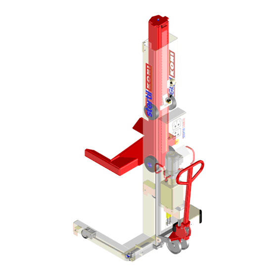
Page 69: Summary Column Lift
List of parts and appendices Summary column lift Figure A.3 Figure Figure A.1 Column lift Operating instructions (Version F) ST 1082 & ST 1100... - Page 70 32741100 Column 130 mm wider model ST 1082VFS 32700116 Top plate 32500109 Shaft 32702200 Guide block ST 1082-FS + RS 32741125 Guide block 130 mm wider ST 1082VFS model 34600200 Guide block ST 1100-FS + RS 34600905 Guide block 130 mm wider...
- Page 71 List of parts and appendices Table A.1 Column lift Index Reference Description Remarks 65025055 Stud bolt M6x30 65003285 Bolt M6x16 DIN 933 65003280 Bolt M6x8 DIN 933 32500107 Support 65003291 Bolt M6x30 DIN 933 32500108 Cable support 65003488 Bolt M14x30 DIN 933 65055023 Washer M14 DIN 125A 66201056...
-
Page 72: Mobile Column Lift
Mobile column lift P6: Locked with loctite 542 sealant Note: Adjustable forks only possible on ST 1082 models. Figure A.2 Mobile column lift Operating instructions (Version F) ST 1082 & ST 1100... - Page 73 List of parts and appendices Table A.2 Mobile column lift Index Reference Description Remarks 32701050 Column Only retractable models 32700111 Shaft Only retractable models 66103909 Ball bearing 60052RSR Only retractable models 32700105 Wheel Only retractable models 32700110 Wheel shaft Only retractable models 65725009 Bolt M10x20 DIN 7984 Only retractable models...
-
Page 74: Hydraulic Unit
Hydraulic unit Figure A.3 Hydraulic unit Operating instructions (Version F) ST 1082 & ST 1100... - Page 75 List of parts and appendices Table A.3 Hydraulic unit Index Reference Description Remarks 68036927 Hydraulic unit 1.2cc, ST 1082 models 3x208/460V, 60Hz, 3800 psi 68037927 Hydraulic unit 1.2cc, 3x575V, ST 1082 models 60Hz, 3800 psi 68035927 Hydraulic unit 1.1cc, ST 1082 models 1x208/230V, 60Hz, 3800 psi 68036929 Hydraulic unit 1.2cc,...
-
Page 76: Hydraulic Scheme
Hydraulic scheme Index Description Cylinder EV22 2/2 Valve VCDF Flow control valve Filter Non return valve Pump Tank Safety pressure valve Electric motor Hose burst check valve X psi ST 1082: 3800 psi ST 1100: 4200 psi Figure A.4 Hydraulic scheme Operating instructions (Version F) ST 1082 &... -
Page 77: Hydraulic Cylinder
List of parts and appendices Hydraulic cylinder Figure A.5 Hydraulic cylinder Operating instructions (Version F) ST 1082 & ST 1100... - Page 78 Table A.5 Hydraulic cylinder Index Reference Description Remarks 32706800 Cylinder (assembly) Bearing ring Backup ring O-ring Bearing ring Piston seal O-ring Backup ring Piston cap 68700450 Straight adaptor 1003.91.80.38 Hose burst check valve 68900000 Air bleeding nipple Cylinder Piston rod Piston Gate Retaining ring...
-
Page 79: Control Box (Master Column)
List of parts and appendices Control box (master column) Figure A.6 Control box (master column) Table A.6 Control box (master column) Index Reference Description Remarks 32707100 Primary control box 3x460V (incl. cables) 32707200 Primary control box 3x208/230V (incl. cables) 32707920 Primary control box 3x575V (incl. - Page 80 Table A.6 Control box (master column) Index Reference Description Remarks 69090112 Connector internals (male) 69090111 Connector internals (female) Cable gland M32x1.5 23254uz13 red Cable gland M20x1.5 22052um2x6 Cable gland M25x1.5 22553um2x8 Cable gland M20x1.5 22052u11 green 69206010 Fuse 125 mAT 250V (F3) 69206012 Fuse 3,15 AT 24V (F2) 69202008...
-
Page 81: Electrical Diagram Control Box (Master Column)
List of parts and appendices Electrical diagram control box (master column) Figure A.7 Electrical diagram control box (master column) Operating instructions (Version F) ST 1082 & ST 1100... -
Page 82: Control Box (Secondary Column)
Control box (secondary column) Figure A.8 Control box (secondary column) Table A.8 Control box (secondary column) Index Reference Description Remarks 32707300 Secondary control box 3x208/230/460/575V (incl. cables) 32707125 69900135 69500007 Trafo 69152006 Motor relay 32707050 Foil covered switch panel 69141061 Emergency stop 69141041 NC contactor... - Page 83 List of parts and appendices Table A.8 Control box (secondary column) Index Reference Description Remarks Cable gland M25x1.5 22553um2x8 Cable gland M20x1.5 22052u11 green 69206010 Fuse 125 mAT 250V (F3) 69206012 Fuse 3,15 AT 24V (F2) 69202008 Acoustical alarm Motor cable Cable lowering valve Cable correction valve Cable unlocking solenoid...
-
Page 84: Electrical Diagram Control Box (Secondary Column)
Electrical diagram control box (secondary column) Figure A.9 Electrical diagram control box (secondary column) Operating instructions (Version F) ST 1082 & ST 1100... -
Page 85: Connection Cable
List of parts and appendices A.10 Connection cable Figure A.10 Connection cable Table A.10 Connection cable Index Reference Description Remarks 32707150 Cable (39' - 9'') assembly Standard 32557150 Cable (39' - 9'') assembly With steel protection (option) 69090111 Connector internals (female) 69090112 Connector internals (male) 69090113... -
Page 86: Pallet Jack Mechanism
A.11 Pallet jack mechanism Figure A.11 Pallet jack mechanism Operating instructions (Version F) ST 1082 & ST 1100... - Page 87 List of parts and appendices Table A.11 Pallet jack mechanism Index Reference Description Remarks 32706200 Pallet jack assembly All models 32706205 Hydraulic valve assembly 32706210 Spring cover assembly 32706215 Pump piston assembly 32706220 Lowering valve assembly 32706225 Lowering screw assembly 32706230 Safety valve assembly 32706235...
-
Page 88: Label Locations
A.12 Label locations Figure A.12 Label locations Operating instructions (Version F) ST 1082 & ST 1100... - Page 89 List of parts and appendices Table A.12 Label locations Index Reference Description Remarks 60700220 User instruction sticker 1005.01.01.92 Type plate 60700189 Sticker "Oil dry piston rod…." 60700061 Large sticker "STERTIL/KONI" 60700092 Sticker "CAUTION" 60700203 Capacity sticker "18.000 lbs" ST 1082 60700145 Capacity sticker "22.000 lbs"...
-
Page 90: Dimensional Drawing
A.13 Dimensional drawing ST 1082-FS (with fixed forks) ST 1082-RS (with adjustable forks) ST 1082VFS (widened model) * 27 1/2" ** 49" Figure A.13.1 Dimensional drawing ST 1082 Operating instructions (Version F) ST 1082 & ST 1100... - Page 91 List of parts and appendices ST 1100-FS (with fixed forks) ST 1100-RS (with fixed forks) ST 1100VFS (widened model) * 27 1/2" ** 49" Figure A.13.2 Dimensional drawing ST 1100 Operating instructions (Version F) ST 1082 & ST 1100...
-
Page 92: B List Of Parts - Options
List of parts - Options The following sections will give an overview of the main assemblies of the variants and options of the Mobile column lifts ST 1082 & ST 1100, and their components: B.1 "Wheel adaptors and column extensions" on page B.2 "Traverse beam"... -
Page 93: Wheel Adaptors And Column Extensions
List of parts - Options Wheel adaptors and column extensions Figure B.1 Wheel adaptors and column extensions Warning Longer wheel adaptors may only be used in combination with column extensions. See the attached label on longer wheel adaptors for the maximum allowed capacity. Operating instructions (Version F) ST 1082 &... - Page 94 Table B.1 Wheel adaptor and extended arm Index Reference Description Remarks 34400920 Wheel adaptor 16" Right ST 1100 (length = 300 mm / 12") 34400925 Wheel adaptor 16" Left ST 1100 (length = 300 mm / 12") 32700920 Wheel adaptor 16" Right ST 1082 (length = 350 mm / 14") 32700925...
-
Page 95: Traverse Beam
List of parts - Options Traverse beam Type: 32591100 MIN. 1000 7,2T 7,2T BELASTINGSGRAFIEK BELASTUNGSSCHEMA DIAGRAMME DE CHARGE LOAD GRAPH A - A (1:10) Figure B.2.1 Traverse beam Table B.2.1 Traverse beam Index Reference Description Remarks 32591100 Traverse beam 32591054 Traverse beam support 66002015 Wheel... - Page 96 Traverse beam 32591510 Traverse beam support 32591020 Adapter adjustable 1020.50.00.30 Wheel 1038.40.04.00 Retaining ring A40 DIN471FF 1005.01.01.49 Stertil-Koni sticker 60700127 Capacity sticker 14400 kg / 32,000 lbs 60700102 Stertil-Koni sticker (medium) Operating instructions (Version F) ST 1082 & ST 1100...
- Page 97 32500116 Wheel 1038.34.02.40 Retaining ring No.24 DIN6799 GV 4310.09.00.10 Pin with clip 32592005 Reducing bush 3,5 to 2 60700102 Stertil-Koni sticker 60700075 Capacity sticker 7200 kg 60700076 Capacity sticker 16000 lbs Operating instructions (Version F) ST 1082 & ST 1100...
-
Page 98: C Inspection Check List
Inspection check list Annual inspection as described in the installation and service manual. Date Remarks Name of mechanic Initials of mechanic pass Operating instructions (Version F) ST 1082 & ST 1100... - Page 99 Inspection check list Date Remarks Name of mechanic Initials of mechanic pass Operating instructions (Version F) ST 1082 & ST 1100...
- Page 100 Index Adjustments Guarantee - - - - - - - - - - 12 pallet lifting mechanism - - - 61 retractable front wheels - - - 62 Annual maintenance- - - - - - 43 Hydraulic oil - - - - - - - - - 44 Column set - - - - - - - - - - 27 Columns Inspection - - - - - - - - - - 42...
- Page 101 Operating system - - - - - - - 24 Traverse beam - - - - - - - - 31 Operation - - - - - - - - - - - 34 tilting - - - - - - - - - - - - 66 lowering - - - - - - - - - - 36 user instruction - - - - - - - 66 pair - - - - - - - - - - - - - 38...
Need help?
Do you have a question about the ST 1082-FS and is the answer not in the manual?
Questions and answers