
Related Manuals for stertil-KONI ST 1082-F/BAT


Summary of Contents for stertil-KONI ST 1082-F/BAT
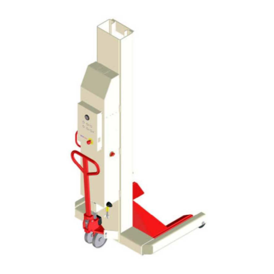
- Page 1 Mobile Column Lifts ST 1082-F/BAT ST 1082-R/BAT Installation - operation – service 32738980-A...
- Page 3 OTHER INSTRUCTIONAL MATERIAL FURNISHED WITH THE LIFT, TO THE LIFT OWNER/USER/EMPLOYER. PLEASE READ AND UNDERSTAND ALL INSTRUCTIONS IN THIS MANUAL BEFORE INSTALLING, OPERATING OR MAINTAINING THIS LIFT DIRECTIONS ASSEMBLY AND SERVICING MANUAL FOR THE 18,000 LBS STERTIL-KONI HYDRAULIC MOBILE COLUMN LIFTS MODEL ST 1082-F/BAT ST 1082-R/BAT Starting at Serial Number TM 139067 This document belongs with mobile column lift no.:...
- Page 4 EC DECLARATION OF CONFORMITY in application of the European 'Machines' Directive (98/37/EC) ALI DECLARATION OF CONFORMITY in application of the ANSI\ALI ALCTV-1998 and UL201 Manufacturer : Stertil B.V., Postbox 23, 9288 ZG Model : ST 1082-F/BAT Fixed wheels and fixed forks KOOTSTERTILLE Holland : ST 1082-R/BAT Retractable wheels and fixed Machine...
-
Page 5: Table Of Contents
Contents Page PREFACE ..................................... 3 GENERAL ................................. 5 1.1 MANUFACTURER'S INFORMATION........................5 1.2 SPECIFICATIONS ............................... 5 DIRECTIONS ................................6 2.1 SCOPE.................................... 6 2.2 GUARANTEE AND LIABILITY ..........................6 2.4 SAFETY MEASURES ..............................7 DESCRIPTION OF THE LIFTING SYSYEM ....................11 3.1 STRUCTURE OF THE COLUMN LIFT ......................... - Page 6 FIG. G - CONNECTION CABLE ............................41 FIG. H - PALLETJACK SERVICE KITS ........................42 FIG. I - LABEL LOCATIONS ............................43 FIG. J - WHEEL ADAPTORS & EXTENDED ARM (OPTION) ................. 44 FIG. K - DIMENSIONAL DRAWING ..........................45 INSPECTION CHECK LIST............................
-
Page 7: Preface
Stertil-Koni USA shall not be responsible for any actions not specifically called out for in this manual or in this notice. Please note that there shall be no modifications or reconstruction made to the Stertil Koni mobile lift without the express written permission of the manufacturer. - Page 8 Please read and understand the attached Statement of Warranty for the Stertil Koni mobile lift. Thank you for the purchase of your Stertil Koni product. Please contact Stertil-KONI USA for the location of authorized Service Centers throughout the United States. Stertil-Koni USA Inc.
-
Page 9: General
29' - 6" lifting columns 900 psi (per front support) – ST 1082-R/BAT Maximum floor suface pressure 7000 psi (per wheel) – ST 1082-F/BAT Maximum floor load 7000 lbs (per front support) Operation temperature 5 to 122° F (-15 to +50°C) -
Page 10: Directions
DIRECTIONS SCOPE This manual refers to the Mobile Column Lift. This manual contains useful and important information for proper functioning and maintenance of the lifting system. It also contains important instructions to prevent accidents and serious damage prior to and during operation of the lifting system, and it enables the product to perform as safely and flawlessly as possible. -
Page 11: Safety Measures
SAFETY MEASURES The lifting system is provided with safety and protection features. Even so, caution is required when using the lifting system. Work safely! Stertil B.V. has made effort to inform you about possible dangers associated with operation of the lifting system. You must ensure and are responsible for compliance with these behavioral guidelines. - Page 12 IMPORTANT SAFETY INSTRUCTIONS - Read all instructions. - If an extension cord is necessary, a cord with a current rating equal to or more than the equipment must be used. Cords rated for less current than the equipment may overheat. Care should be taken to arrange the cord so that it will not be tripped over or pulled.
- Page 13 - Care must be taken as burns can occur from touching hot parts. - Prevent damage to the power feed cables on account of driving over or heavy or falling objects. - Do not drive over interconnecting cables. Always disconnect interconnecting cables and remove from vehicle travel path before moving vehicle.
-
Page 15: Description Of The Lifting Sysyem
DESCRIPTION OF THE LIFTING SYSYEM Column For the hydraulic system diagram see figure L. Potentiometer Mechanical lock The mobile column lift is a movable electrically driven hydraulic Hydraulic unit column lift used for lifting heavy vehicles. At least two lifting Control box Electrical connector columns are required for lifting a vehicle. -
Page 16: Structure Of The Column Lift
- At a difference in height of over 1 1/4" and less than 2 3/8", lowering is interrupted. A lifting fork may be blocked; the cause of the failure must then be traced first. Lifting is still possible, the adjustment valve in the hydraulic system will open and remain open until the difference has been cancelled out. -
Page 17: Installation
• Mechanical safety lock If the hydraulic pressure fails while a vehicle is on the lifting system or is lifted or lowered, a mechanical safety lock ensures that it cannot drop. The characteristic clicking of the safety lock when lifting, indicates that it is activated. During lowering the pawl is retracted by a solenoid. -
Page 18: General Use
GENERAL USE CONTROL All functions of the lifting system are controlled from the control panel on the column. The main switch is positioned on the right side of the cover. The functions of the switches, buttons and knobs on the primary control panel are described below (see Fig. 5.1). 1. - Page 19 The control system of the mobile column lift is set-up as follows: 1. Connect the lifting columns in a full circuit as indicated in 5.2, Connecting Lifting Columns. - The column sequence in this circuit can be selected at random columns can be positioned at any place, provided the maximum lifting capacity of 72,000 lbs is not exceeded as described in 5.2.
-
Page 20: Wheel Adapters (Optional)
WHEEL ADAPTERS (OPTIONAL) The mobile lifting columns can be used to lift vehicles with a wheel diameter of R12 (500 mm, 19 ¾”) to R22.5 (1140 mm, 45”). Wheel adapters (fig. 5.4) are required for use with different wheel diameters. Two adapters are required for tire size of R12 (500 mm, 19 ¾") to R15 (650 mm, 25 ½"). -
Page 21: Adjustable Forks (Option)
ADJUSTABLE FORKS (OPTION) The mobile lifting columns can be used to lift vehicles with a wheel diameter of R10 (450 mm, 17 ¾”) to R22.5 (1140 mm, 45”). The forks can be slided to the correct dimension: Lift T-handle to unlock the fork. (fig. 5.6-a Use both hands to slide the fork sideways. -
Page 22: Operating The Pallet Lifting Mechanism
OPERATING THE PALLET LIFTING MECHANISM 1. Set the lever to position (3) and make a pumping movement with the drawbar, to raise the column lift with the pallet lifting mechanism. The column lift can then be relocated. 2. Pull the lever to position (1) to lower the column lift to the floor. 3. -
Page 23: Vehicle Technology
VEHICLE TECHNOLOGY IMPORTANT: Basically single and paired operation are only meant for levelling a vehicle and/or in combination with axle stands. Safety guideline parameters: For single operation the maximum allowed height difference is 2 inches. For paired operation the maximum allowed height difference between front and rear axle is 6 inches. -
Page 24: Operation
OPERATION The assembled lifting system must be checked for correct working and adjustments and a complete operational test should be carried out by using a typical vehicle. Remarks: - When using this lifting system leave a space for a 24" wide passage around the lifting system which can serve as escape route. -
Page 25: Emergency Release
EMERGENCY RELEASE In emergency situations it is possible to lower the lifting columns manually. Manual lowering must only be performed by a qualified engineer. INSPECTION AND MAINTENANCE GENERAL All maintenance on the lifting equipment must be performed only by trained lift service personnel. -
Page 26: Monthly (By Operator)
If batteries need replacement only use the original equipment from Stertil-KONI. Universal car type batteries may release highly explosive gasses under normal charging conditions. Replacement of batteries must be done by skilled service people. -
Page 27: Annually (By Service Department)
ANNUALLY (BY SERVICE DEPARTMENT) Check the mechanical safety lock (see fig. 7.1). • Set the lifting columns in the lowest position (if necessary, use the internal switch SET+ and SET- in the control box). • Raise the lifting columns to the first locking position and then lower into it. -
Page 28: Maintenance Switches
MAINTENANCE SWITCHES Maintenance switches are located inside the control box to assist the technician when servicing the lifting system (see fig. 8.1). These switches can be used to check the correct functioning of the lowering valve, unlock solenoid and the hydraulic unit. As long as the control system is still functional, the switches can also be used to check the safety margins for control. -
Page 29: Adjusting The Pallet Jack Mechanism
ADJUSTING THE PALLET JACK MECHANISM When moving the handle bar up and down, with the lever in position 3 (see fig. 7.7), the cylinder should at the correct setting be raised approx. 5/16" per stroke. Set the lever to position 2 and move the handle bar up and down; at a correct setting the cylinder will not be raised now. -
Page 30: Service
SERVICE GENERAL Attention: All repairs carried out on the lifting system by non-service department personnel, the consequences of such repairs are entirely at the user's risk. The term 'service department' is the Stertil service department or a service department recognized by Stertil. Two tables are provided to assist the service technician in locating faults in the lifting system . - Page 31 MICROPROCESSOR BOARD Fig. 8.1, Location of fault indication LED’s...
-
Page 32: Trouble-Shooting
TROUBLE-SHOOTING POSSIBLE FAULT REMEDY INDICATION Potentiometer Fault Check the wiring to the potentiometer. Hold “SET REF” button for 2 sec until control light is on. If the fault occurs again, contact the Stertil B.V. Service Department. Communication Fault Check the connecting cables between the boxes. Connect one auxiliary box to the main box using - preferably - new cables. - Page 33 FAULT POSSIBLE CASE REMEDY No battery power. Check main fuse above batteries inside cover. Have Column does not lift. batteries tested by qualified battery supplier Oil level too low. Add oil as necessary, refer to lubricating instructions on lifting column. Press the ⇑...
- Page 34 FAULT POSSIBLE CASE REMEDY The cylinder seal is damaged, oil Have seals or cylinder replaced by service department. Column lowers by leaks continually. itself. Leaks in the oil line couplings. Tighten couplings and coupling nuts. Dirty or damaged non-return Clean the filter and the ball behind the filter. valve.
-
Page 35: Identification
Index: The numbers in this column refer to the numbers in the parts drawing. Reference: The numbers in this column are STERTIL-KONI part numbers. Please give these numbers when ordering. Description: This column gives the name of the parts. ORDERING SPARE PARTS Replacement parts can be ordered from Stertil, for addresses see §1.1. -
Page 36: Fig. A - Mobile Lifting Column
FIG. A - MOBILE LIFTING COLUMN INDEX REFERENCE DESCRIPTION INDEX REFERENCE DESCRIPTION ST 1082-BAT ST 1082 1 See fig. E/F Cover / Control Box 27 65050144 Nut M20 DIN934 2 30501003 Packing ring 28 1035.38.04.11 Bolt M6x10 DIN933 3 66201039 Nut cap M20 0342044 29 65055015 Washer M6 DIN125A... - Page 37 FIG. A...
-
Page 38: Fig. B - Mobile Lifting Column
Nut M8 DIN 439B All models 32550103 Shaft All models 32700120 All models 32700250 Balancer Only ST 1082-R/BAT 32700300 Balancer Only ST 1082-F/BAT 32550102 Shaft All models 60203002 Gas spring All models 60203003 Clamp All models 65762024 Retaining ring Nr. 9 DIN 6799... - Page 39 FIG. B Item 6 locked with loctite 542 sealant...
-
Page 40: Fig. C – Hydraulic Unit
FIG. C – HYDRAULIC UNIT INDEX REFERENCE DESCRIPTION REMARKS 68038427 Hydr. unit 1.2cc, 24V 265 bar/3800 psi 68039011 Tank plastic 10 liter/2.64 gallon 68510911 O-ring 110.72x3.53 mm 32506103 Suction filter D.62 dia. 3/8" 32006254 Return filter 10 micron 32516105 Pump 1.2 CM3/REV Tightening torque 16.5 lbf ft 68308013 2/2 Valve NC (ex. -
Page 41: Fig. D – Hydraulic Cylinder
FIG. D – HYDRAULIC CYLINDER INDEX REFERENCE DESCRIPTION ST 1082 32706800 Cylinder (assembly) Cylinder bottom 68515702 Oring Ø70x2.5 Retaining ring Piston seal 68515402 Oring Ø50x2 Piston Cylinder Piston rod * 10 Bearing ring Retaining ring Piston cap 1003.91.80.38 Hose burst check valve 68700450 Union GE10 PSR 1/4"... -
Page 42: Fig. E - Control Box
FIG. E - CONTROL BOX... - Page 43 FIG. E - CONTROL BOX NDEX REFERENCE DESCRIPTION ST 1082-BAT 32737100 Control box (incl. cables) 68039013 Motor relays 24Vcc 150A 69500104 Battery charger Mean Well 230/110V 24V 10.5A 69120026 Battery switch PN 9006 69206403 Fuse holder 5007 Class T 110-200A 69206102 Fuse 200A 300V A3T200 69800001...
-
Page 44: Fig. F – Schematic Diagram
FIG. F – SCHEMATIC DIAGRAM... -
Page 45: Fig. G - Connection Cable
FIG. G - CONNECTION CABLE INDEX REFERENCE DESCRIPTION REMARKS 32737160 Cable (39’ – 9’’) assembly) 69090106 Housing 69090108 Connector internals (female) 69090109 Connector internals (male) -
Page 46: Fig. H - Palletjack Service Kits
FIG. H - PALLETJACK SERVICE KITS INDEX REFERENCE DESCRIPTION REMARKS 32706205 Hydraulic valve ass’y 32706210 Spring cover ass’y 32706215 Pump piston ass’y 32706220 Lowering valve ass’y 32706225 Lowering screw ass’y 32706230 Safety valve ass’y 32706235 Pump unit 32706240 Handle ass’y 32706245 Seal kit... -
Page 47: Fig. I - Label Locations
FIG. I - LABEL LOCATIONS INDEX REFERENCE DESCRIPTION ST 1082 60700224 User instruction sticker 1005.01.01.92 Type plate 60700189 Sticker “Oil dry piston rod….” 60700061 Large sticker "STERTIL/KONI" 60700092 Sticker "CAUTION" 60700203 Capacity sticker "18.000 lbs" 60700093 Sticker "WARNING" 60700090 Address sticker "STERTIL KONI USA" 60702001 ALI member label 60702004... -
Page 48: Fig. J - Wheel Adaptors & Extended Arm (Option)
FIG. J - WHEEL ADAPTORS & EXTENDED ARM (OPTION) INDEX REFERENCE DESCRIPTION REMARKS 32503050 Wheel adaptor 16" (length = 300 mm / 12") All models 34000930 Wheel adaptor 16" (length = 500 mm / 20") Only for ST 1082F (fixed wheels) Max. 8,800 lbs 32550905 Longer wheel adaptor (length = 500 mm / 20") Only for ST 1082F (fixed wheels) Max. -
Page 49: Fig. K - Dimensional Drawing
FIG. K - DIMENSIONAL DRAWING ST 1082-F/BAT (with fixed forks) ST 1082-R/BAT (with adjustable forks option) ST 1082-F/V/BAT (widened model) * 27 ½ ” ** 49 ”... -
Page 50: Inspection Check List
INSPECTION CHECK LIST Annual inspection as described under 7, "Inspection and Maintenance". Date Remarks Name of mechanic Initials of mechnicpass... - Page 52 Manufactured by: STERTIL B.V. P.O. Box 23, 9288 ZG Kootstertille (Holland) Tel. 31(0)512334444. Telefax 31(0)512334430. www.stertil.nl email: info@stertil.nl...
Need help?
Do you have a question about the ST 1082-F/BAT and is the answer not in the manual?
Questions and answers