
Related Manuals for stertil-KONI ST1075-FBF


Summary of Contents for stertil-KONI ST1075-FBF
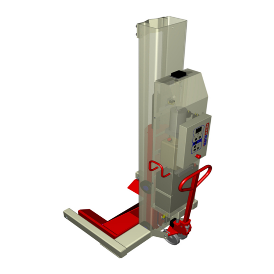
- Page 1 Mobile column lift ST1075-FBF Installation, operation maintenance instructions © 2013 Stertil B.V. 34508860-0...
- Page 2 FURNISHED WITH THE LIFT, TO THE LIFT OWNER / USER / EMPLOYER. PLEASE READ AND UNDERSTAND ALL INSTRUCTIONS IN THIS MANUAL BEFORE INSTALLING, OPERATING OR MAINTAINING THIS LIFT. Installation, operation and maintenance instructions for the Stertil-Koni hydraulic mobile column lifts: ST 1075-FBF Capacity:...
-
Page 3: Table Of Contents
Contents Statement of conformity - - - - - - - - - - - - - - - - - - - - - 7 Preface - - - - - - - - - - - - - - - - - - - - - - - - - - - - - - 9 General - - - - - - - - - - - - - - - - - - - - - - - - - - - - - 11 Copyright - - - - - - - - - - - - - - - - - - - - - - - - - - - - 11 Limitations of the document - - - - - - - - - - - - - - - - - - - 11... - Page 4 Linking the column lifts- - - - - - - - - - - - - - - - - - - - - - 29 Safety when hoisting- - - - - - - - - - - - - - - - - - - - - - - 29 Traverse beam (option) - - - - - - - - - - - - - - - - - - - - - 32 Testing - - - - - - - - - - - - - - - - - - - - - - - - - - - - - 32 Operation- - - - - - - - - - - - - - - - - - - - - - - - - - - - 33...
- Page 5 Programmable settings - - - - - - - - - - - - - - - - - - - - - 51 7.3.1 Height limit - - - - - - - - - - - - - - - - - - - - - - - 51 7.3.2 Unlock during up - - - - - - - - - - - - - - - - - - - - 52 7.3.3...
- Page 6 Hydraulic scheme - - - - - - - - - - - - - - - - - - - - - - - - 80 Hydraulic cylinder - - - - - - - - - - - - - - - - - - - - - - - - 81 Control box - - - - - - - - - - - - - - - - - - - - - - - - - - 83 Electrical diagram control box - - - - - - - - - - - - - - - - - - 86...
-
Page 7: Statement Of Conformity
Statement of conformity Statement of conformity with the European Machinery Directive (2006/42/EC) and with the ANSI/ALI ALCTV 2006 and UL 201 2-nd edition. Manufacturer: Stertil B.V. Postbus 23 9288 ZG Kootstertille Nederland Machine: Hydraulic mobile column lifts Trademark: STERTIL - KONI Serial Numbers: . - Page 8 The manufacturer is authorized to constitute the technical documentation. The undersigned, U. Bijlsma, General Manager, authorized for this purpose by Stertil B.V., hereby declares that the mobile column lift described above conforms with the fundamental safety requirements set down in: •...
-
Page 9: Preface
Preface Prior to the operation of your Stertil Koni mobile lift, make sure that you read the instructions thoroughly. These instructions are found in this manual. Please note that your warranty can be voided if you do not read the manual and understand its contents If you have any questions concerning operation, safety or application of your mobile lift, please contact Stertil Koni USA at the following toll free number:... - Page 10 ANSI/Z244.1 1982. Note ‘Trained lift service personnel’ refers to personnel of the Stertil-Koni service department or another servicing agency recognized by Stertil-Koni, both also designated as ‘service department’. The consequences of all repairs carried out on the vehicle lift by non-trained lift service personnel, are entirely at the user's risk.
-
Page 11: General
General Copyright Copyright 2013 Stertil B.V. All rights reserved worldwide. No part of this publication, including drawings and diagrams, may be reproduced and/or published, whether by printing, photocopying, microfilm or by any other means whatsoever, without the prior written permission of Stertil B.V. -
Page 12: Scope Of This Manual
Persons who are not familiar with the operation and installation of type ST 1075 mobile column lifts are advised to read the following chapters thoroughly and to follow the instructions given exactly. Persons who are familiar with the operation and installation of type ST 1075 mobile column lifts can use this manual as a reference. -
Page 13: Manufacturer's Details
General Manufacturer's details Stertil B.V. P.O. Box 23 9288 ZG Kootstertille Telephone (international): +31(0)512 334 444 Telephone (national): (0)512 334 441 Fax: +31(0)512 332 638 E-mail: info@stertil.nl Website: www.stertil.nl Guarantee and liability Please refer to the delivery terms and conditions, and the order confirmation. Environmental aspects The owner and/or user of the mobile column lifts is responsible for the disposal of waste materials (oil, etc.) in accordance with the applicable local laws or regulations. -
Page 14: Safety
Safety Introduction Our safety requirements may under no condition conflict with the statutory requirements and rules that apply to the safety of the mobile lift. Whenever one of the warnings or safety requirements conflicts with existing local legislation, the most stringent rule will always take precedence. - Page 15 Safety The buyer/user is obliged to familiarize operating, cleaning and maintenance personnel with these instructions. Upon their arrival, check deliveries for: • Any damage and/or missing parts due to transport. Make sure that the carrier draws up a transport damage report on the spot. •...
- Page 16 • Keep hair, loose clothing, fingers and all parts of the body away from moving parts. • To reduce the risk of electrical shock, do not use on wet surfaces or expose to rain. • Use only as described in this manual. Use only manufacturers recommended attachments.
- Page 17 Safety • Do not operate equipment with a damaged cord or if the equipment has been dropped or damaged until it has been examined by a qualified serviceman. • In case of using one or two lifting columns (in paired operation), be sure that this will not result in stability risks.
-
Page 18: Manufacturers Instructions To The Lift Owner/Employer
• Always lower the mobile column lifts into the safety lock before starting any work on the vehicle or leaving the vehicle unattended. FOR YOUR AND OTHER PEOPLES SAFETY: SAVE THESE INSTRUCTIONS. Warning All accessories supplied with this lift are to be used on this lift only. Accessories from other lifts are not acceptable and could result in injury to the user. -
Page 19: Safety Measures
Safety • Provide necessary lockout/tagout means for energy sources per ANSI Z244.1-1982 (R1993), Safety Requirements for the Lockout/Tagout of Energy Sources, before beginning any lift repairs. • Not modify the lift in any manner without the prior written consent of the manufacturer. -
Page 20: Safety Instructions, Caution And Warning Labels
Safety instructions, caution and warning labels The following safety and warning labels may be used on the mobile lift: Figure 2.1 Safety and warning labels Operating instructions (Version 0) ST 1075... - Page 21 Safety Figure 2.2 Safety and warning labels Operating instructions (Version 0) ST 1075...
-
Page 22: Specifications
Specifications General The general specifications are also printed on the type plate on the mobile column lift. Table 3.1 Specifications Model ST 1075-FBF Lifting capacity 16,500 lbs Pressure relief valve 3,800 psi (sealed with plastic cap ex- works) Maximum lifting height 69"... -
Page 23: Lifting Capacity
Specifications Lifting capacity Table 3.1 for specifications of the maximum lifting capacity. The overpressure safeguard in the hydraulic unit has been preset so that the lift can never raise more than the specified weight +10%. The design is calculated for a maximum load of 16,500 lbs on any one column. Lifting system This mobile column lift is an electrically driven hydraulic column lift for lifting heavy vehicles. -
Page 24: Control System
The columns are coupled together by an identification procedure (with an ID key). The control signals that ensure synchronised movement of the columns, are transmitted through the air. Control system The control system on the columns ensures that raising and lowering of the column lifts is simultaneous and synchronised, independent of the load distribution on the columns. -
Page 25: Column, Lifting Cylinder And Guide Block
Specifications Column, lifting cylinder and guide block The column and lifting cylinder together form the most important part of the mobile column lift. A guide block with rollers is located within the U-shaped profile of the column. The rollers enable the guide block to move up and down the entire length of the column. -
Page 26: Installation
Installation Unpacking and setup Proceed as described below when unpacking and setting up each column. Warning Only use proper lifting equipment to move the column lift. Lift the column only at the points intended for this. Failure to relocate the column lift in the right manner can cause damage to the column lift and/or personal injury. - Page 27 Installation Hang the entire assembly for the control cabinet on the bracket on the column. Remove the two M6 bolts and open the door. Fix the frame in place with the four M6 bolts. Attach the potentiometer (PTM) plug. Connect the locking magnet (VLM) plug. Remove the stoppers and connect up the hydraulic hose.
- Page 28 1. Control box 8. Charging cable connector 13. Neg. battery terminal-pos. 2. Relay (24V/150A) 9. Charging cable battery terminal cable 3. Battery charger 10. Relay-motor cable 14. Neg. battery terminal-motor 4. Main switch 11. Switch-fuse cable cable 5. Fuse holder 12.
-
Page 29: Linking The Column Lifts
Installation Also attach the negative cable (3) from the battery charger to the negative terminal of the bottom battery. Connect the positive of the black connector cable (13) to the positive of the battery. Place the top battery with the negative terminal on the same side as the battery charger. - Page 30 Safety guidelines: • When operating an individual column lift, the maximum permissible elevation difference is 2 inches. • When operating two column lifts (per-axle control), the maximum permissible elevation difference between the front and rear axles is 6 inches. • With a tandem axle at the rear of the vehicle, the maximum permissible elevation difference between both rear axles is 2 inches.
- Page 31 Installation If one of the columns is lowered too far, it can have the following consequences: • No load on that particular column. • No load on the column diagonally opposite. • Double load on the remaining columns. No load Centre of gravity of the vehicle 66,000 lbs 33,000 lbs...
-
Page 32: Traverse Beam (Option)
Traverse beam (option) For the lifting and lowering of trailers on a set of mobile lifting columns, a special Stertil-Koni traverse beam is available. For the operating procedures and safety precautions of the traverse beam, see 8.2 "Traverse beam" on page... -
Page 33: Operation
Operation General The mobile column lifts are designed to provide maximum flexibility and ease of use. A lifting system may consist of 2 to 8 columns in total. The following possibilities are available within the control system: • operating all column lifts simultaneously, •... -
Page 34: Control Box
Control box All functions of the lifting system are controlled from the control box on the column lift (see Figure 5.2 1. Emergency stop button 7. Slow lowering selection 12. ID key reader 2. Information screen button (antenna) 3. UP button 8. - Page 35 Operation To start the mobile lift (see Figure 5.2 • Select an (even) number of columns (2-8) that are jointly to define a set. • Check that all the emergency stop switches are unlocked. • Place the columns with the forks around the wheels of the vehicle. •...
- Page 36 The columns are now linked. This is shown by: <4 COLUMNS FOUND>. STARTUP COMPLETED COLUMNS FOUND Figure 5.5 instructions on the screen and then immediately afterwards, <READY>. READY Figure 5.6 instructions on the screen The mobile lift is now ready for use. Note The ID key allows any random set from a number of columns to be linked together.
-
Page 37: Raising
Operation 5.2.3 Raising To raise the column lifts, press the UP button (3). There is an arrow pointing up beside this button. 5.2.4 Lowering Operate button (6) simultaneously with button (4) to lower the column lifts. There is an arrow pointing down next to button (4). Note If the foot protection has been enabled, the lowering action will be interrupted at approx. -
Page 38: Information Screen
The buttons for raising, normal lowering and lowering in the safety locks are of the "dead man" type (hold to run). Operation continues as long as the button remains pressed, and stops immediately once the button is released. Note In the event of malfunction, consult the troubleshooting section (see 7.5 "Troubleshooting"... -
Page 39: Setting The Columns
Operation Setting the columns 5.3.1 Operating system Link the columns - see 5.2.2 "Starting and identification" on page All system functions are now available (the default is <ALL> all columns): - button 3 = all columns will be raised, - button 4 = all columns will be lowered into the safeguard, - buttons 6 and 4 = all columns will be lowered. -
Page 40: Operating The Pallet Lifting Mechanism
Operating the pallet lifting mechanism Set the lever to position (3) and make a pumping movement with the drawbar, to raise the column lift with the pallet lifting mechanism. The column lift can then be relocated. Lever Drawbar Figure 5.8 Pallet lifting mechanism Pull the lever to position (1) to lower the column lift to the floor. -
Page 41: Preparation
Operation • the pallet lifting mechanism is set to the bottom position. 5.5.1 Preparation Fit wheel adapters to the forks of the column lifts if necessary. Set up the required number of column lifts. Ensure that the fork of each column lift is extended as far as possible under the wheel. -
Page 42: Unblocking In Case Of Emergency
Note Turn the main switch off when the columns are not in use. The (slight) power consumption of the controller can discharge the batteries, so that raising and lowering become impossible. The system switches itself off complete discharge is imminent. When using just one or two column lifts (when operating in pairs), make certain that there is no possible danger of instability;... -
Page 43: Inspection And Maintenance
Inspection and maintenance General Always completely lower the column lifts and switch off the mains power switch (position 0) during inspection and maintenance. The power may be only temporarily switched on, and the lift placed in a higher position, when required for performing certain checks and adjustments. Warning When the column lifts are in a raised position, always lower them into the safety lock. -
Page 44: Annual Maintenance By Trained Lift Service Personnel Only
6.2.3 Annual maintenance by trained lift service personnel only The user must have the column lifts inspected once a year by the Stertil technical service or another technical service authorized by Stertil (both hereafter referred to as the technical service). A maintenance subscription can be taken out with the technical service for this annual inspection. -
Page 45: Maintenance Procedures
Inspection and maintenance For additional details, see chapter 7 "Service and troubleshooting" on page Table 6.1 Lubrication program Every 2 Annual years Maintenance tasks Description Monthly (technical (technical service) service) Cylinder Lubricate piston rod if dry (machine oil) Check oil level in tank Top up (only with column lifts fully lowered) -
Page 46: Checking The Safety Battery Capacity
Fill the tank with UNIL HVD S15 (ISO VG15) hydraulic oil filtered at maximum 4 microns. Quantity of hydraulic oil in the tank: 2.6 gallon. 6.3.3 Checking the safety battery capacity The battery capacities must be checked daily. The battery capacity can be read off on the left of the screen. Battery meter (full) READY Figure 6.1 battery capacity... -
Page 47: Checking The Emergency Shutdown Mechanism
Warning Do not use an external battery charger (booster) to charge the batteries. Only use the built-in Stertil-Koni battery charger. Loading the batteries with a standard charger can cause explosive gases to be produced. 6.3.4 Checking the emergency shutdown mechanism Press the emergency shutdown button on the auxiliary boxes while the column lifts are moving. -
Page 48: Maintenance Switches
Adjust the top position end stop as follows: move the column lifts to its lowest position and look at the display. If the height is not 0", then the potentiometer rod must be adjusted. This is only possible at the highest position. The highest position can only be reached by using the maintenance switches at the rear side of the electrical panel (see section 6.3.6 "Maintenance switches"... -
Page 49: Batteries
Clean the battery terminals if necessary and tighten them. Warning Only replace the batteries with original Stertil-Koni batteries. Universal (car) batteries can produce explosive gases during normal charging. Recharging defective or totally discharged batteries can cause explosive gases to be produced. -
Page 50: Service And Troubleshooting
Service and troubleshooting General Faults in the column lifts can have simple causes. Check the installation for the possible causes indicated. If troubleshooting as described below fails to correct the malfunction, please contact technical services. Most errors can be corrected without having to remove the vehicle from the column lifts. -
Page 51: Programmable Settings
Service and troubleshooting Programmable settings Pressing <SELECT> and <SLOW LOWERING> (turtle) continuously for 2 seconds activates the service menu. The screen looks like this: SERVICE MENU Height limit Unlock during up Crush limit Height diff.guard Height guard Odd nr of columns Figure 7.1 Service menu The functions can be selected using the <UP>... -
Page 52: Unlock During Up
7.3.2 Unlock during up This option is available so that the pawls are operated when the UP button is operated. This will suppress the clicking noise while raising. This function has no effect on the safety of the column lift. The pawl will be pulled in again when the <UP>... -
Page 53: Odd Number Of Columns
Service and troubleshooting The screen shows the messages <Warning 15> and <Height guard is off>. There is also an acoustic signal when raising or lowering to alert the operator to the fact that this servicing operation is enabled. Note This setting is active for 2 minutes and the height difference guard is then automatically switched back <ON>... -
Page 54: Motor Run Time Hours
7.3.9 Motor run time hours This shows the time (in hours and minutes) that the motor has run for. The time is stored by the controller and cannot be reset. If a new PCB is fitted, though, the measurement will start at zero again. 7.3.10 System run time This shows the time (in days and hours) that the controller has run for. -
Page 55: Motor Type
Service and troubleshooting 7.3.14 Motor type This setting is used to select the type of motor. • DC = standard direct current motor with brushes (no speed controller). • AC = low voltage (3x24V) three-phase motor and motor controller (Curtis) with speed regulation. - Page 56 When raising: The raising motion stops and the message <Maximum height reached> appears on the screen. WARNING 2 Maximum height reached Figure 7.3 Warning while raising One of the columns has reached its highest position. The column lifts can be lowered normally.
-
Page 57: Service Sticker
Service and troubleshooting 7.4.1 Service sticker Figure 7.4 Service sticker The service sticker is behind the control box. The items stated on the sticker include the type of main fuse used and how the various components on the controller PCB are connected. -
Page 58: Electrical Diagram For Control Box
7.4.2 Electrical diagram for control box For an overview of the electrical components and the electrical diagram, refer to section A.6 "Electrical diagram control box" on page 7.4.3 Hydraulic components For an overview of the hydraulic components and the hydraulics diagram, refer to section A.3 "Hydraulic scheme"... - Page 59 Service and troubleshooting Table 7.2 Warnings Code Screen text Possible cause Solution Weak battery. Battery has not been Set the system charging. Lowering and recharged for a shortly up while. possible. Low battery. More than 15 Set the system charging. No more movements on a movements...
-
Page 60: Error Reports
7.5.2 Error reports When there is an error, further operations are locked out. This is shown on the screen as follows: ERROR 5 Other column has an error/failure Figure 7.6 Error report The error has to be cancelled first. Pressing <SELECT> and <UNLOCK> continuously for 2 seconds resets the system. Table 7.3 Troubleshooting Code Screen text... - Page 61 Service and troubleshooting Table 7.3 Troubleshooting Code Screen text Possible cause Solution Potentiometer The potentiometer's Check the potentiometer short circuit or slider is loose or wiring. loose. causing a short circuit. Main relay Main relay defective Check the wiring to the main driver.
- Page 62 Table 7.3 Troubleshooting Code Screen text Possible cause Solution Internal main The main relay on Check whether the relay not active the PCB is not emergency stop switches are or emergency switching. unlocked; otherwise replace loop open. the PCB. Emergency One of the Check whether all the loop open.
-
Page 63: Fault Messages
Service and troubleshooting 7.5.3 Fault messages If there is a fault, the radio network will be cancelled and a red light (FAULT) will be continuously illuminated on the front panel. On the screen, it looks like this: FAILURE 71 No communication with the master column Figure 7.7 Fault message Before the system can be restarted (see... - Page 64 Table 7.4 Fault messages Code Screen text Possible cause Solution Hardware An error has Reboot the system. If the fault failure: occurred on the PCB. occurs again, contact technical services. internal RAM. Hardware failure: external watchdog. Hardware failure: EPROM. Hardware failure: external RAM.
-
Page 65: Troubleshooting Overview
Service and troubleshooting 7.5.4 Troubleshooting overview Table 7.5 The column lift cannot be raised Cause Solution No battery power. Check the main fuse above the batteries. Have the batteries checked by a battery specialist. Oil level too low (but motor running). Top up;... - Page 66 Table 7.6 The column lift cannot be lowered Cause Solution The maximum elevation difference (more than Press <UP> until the height difference has 1 1/4") has been exceeded. been levelled out. If lifting is not required, you can press the <SELECT>...
- Page 67 Service and troubleshooting Table 7.9 No battery power Cause Solution No battery power. Charge the batteries using the mains cable supplied. DO NOT USE AN EXTERNAL BOOSTER CHARGER. Have the batteries checked by a battery specialist. The main fuse has blown. Check the main fuse above the batteries.
-
Page 68: Maintenance Procedures
Maintenance procedures 7.6.1 Removal and installation of the lifting cylinder Proceed as follows to remove the cylinder: Remove the bolt and the retaining tube at the bottom of the guide block. Press the <SELECT> button until the <SINGLE> button is illuminated. Then press the <DOWN>... -
Page 69: List Of Parts
Service and troubleshooting Set the lever to position 2 and move the drawbar up and down; the cylinder will now not lift if the setting is correct. If the cylinder lifts, loosen nut 1 and turn the adjusting screw clockwise. If the cylinder sinks down, turn the adjusting screw anti-clockwise until the cylinder no longer sinks. -
Page 70: Emergency Lowering Facility
Emergency lowering facility If there is a power failure, you will be unable to use the control buttons to lower the lift. In such a case, it is possible to let the lift down manually. Please contact technical services in this case. Warning The emergency lowering procedure may only be performed by persons who are trained in this procedure. -
Page 71: Options
Options Wheel adapters The mobile column lifts may be used to hoist vehicles with a wheel diameter ranging from R12 (20") to R22.5 (45"). Wheel adapters must be used for certain wheel diameters (see Figure 8.1 Figure 8.1 Wheel adapters For tyre sizes R12 (20") to R15 (26"), two adapters are needed. -
Page 72: Longer Wheel Adapters
8.1.1 Longer wheel adapters Special 6 inches longer wheel adapters (see Figure 8.2 ) can be supplied for hoisting vehicles with double wheels such as trucks, buses, etc. and for vehicles with an overhanging body (camper vans, etc.). Figure 8.2 Longer wheel adapters Warning These longer wheel adapters may only be used in combination with the column foot extensions. -
Page 73: Traverse Beam
Traverse beam For the lifting and lowering of trailers on a set of mobile lifting columns, a special Stertil-Koni traverse beam is available. 8.2.1 Before you start working Check both the maximum lifting capacity of the traverse beam and the maximum lifting capacity of a set of two mobile columns. - Page 74 During this horizontal movement, it is possible that the traverse beam starts to tilt, as shown in Figure 8.4 Figure 8.4 Tilted traverse beam Caution Tilting of the traverse beam is a potential hazardous situation. Whether this situation will occur depends on the specific design of the trailer. To prevent this dangerous situation: Always connect the (brake) air pressure to the trailer from an external source.
-
Page 75: List Of Parts And Appendices
List of parts and appendices The following sections will give an overview of the main assemblies and their components: A.1 ‘Summary column lift” on page A.2 ‘Hydraulic unit” on page A.3 ‘Hydraulic scheme” on page A.4 ‘Hydraulic cylinder” on page A.5 ‘Control box”... -
Page 76: Summary Column Lift
Summary column lift Figure Figure A.2 Figure A.1 Column lift Operating instructions (Version 0) ST 1075... - Page 77 List of parts and appendices Table A.1 Column lift Index Reference Description Remarks Figure A.5.1 Cover / Control Box 30501003 Packing ring 34200116 Locking bush 1020.50.00.30 Roller 32700101 Angle support 32500116 Wheel 34500150 Column 34200117 Plate 32500109 Shaft 34500200 Guide block 69090050 Grommet No.
-
Page 78: Hydraulic Unit
Hydraulic unit Figure A.2 Hydraulic unit Operating instructions (Version 0) ST 1075... - Page 79 List of parts and appendices Table A.2 Hydraulic unit Index Reference Description Remarks 68038427 Hydr.unit 1.2cc 24V 265 Bar 68039011 Tank plastic 9 liter 68510911 O-ring 110.72x3.53 mm 32506103 Suction filter D.62 dia. 3/8" 32006254 Return filter 10 micron 32516105 Pump 1.2 CM3/REV Tightening torque 16.5 lbf ft 68308013...
-
Page 80: Hydraulic Scheme
Hydraulic scheme 6 L/min Index Description Cylinder EV22 2/2 Valve VCDF Flow control valve Filter Non return valve Pump Tank Safety pressure valve Electric motor Hose burst check valve X psi 3,850 psi Figure A.3 Hydraulic scheme Operating instructions (Version 0) ST 1075... -
Page 81: Hydraulic Cylinder
List of parts and appendices Hydraulic cylinder Figure A.4 Hydraulic cylinder Operating instructions (Version 0) ST 1075... - Page 82 Table A.4 Hydraulic cylinder Index Reference Description Remarks 34400600 Cylinder (assembly) Cylinder bottom O-ring Ø56,74x3,53 Backup ring Retaining ring Piston seal Bearing ring O-ring Ø34x3 Backup ring Piston Cylinder Piston rod Guide post Bearing ring Piston cap 68228005 Hose burst check valve 68700451 Union GE 10-PSR 1/4"...
-
Page 83: Control Box
List of parts and appendices Control box Figure A.5.1 Control box Figure A.5.2 Control box Operating instructions (Version 0) ST 1075... - Page 84 Table A.5 Control box Index Reference Description Remarks 32739100 Control box wireless (incl. cables) 68039013 Motor relays 24Vcc 150A 69500104 Battery charger 230/115V 24V 10.5A 69120026 Battery switch 69206403 Fuse holder 69206102 Fuse 200A 300V A3T200 69302016 Battery 12V/104Ah VDC31M VMF 32739160 Connector PX0580/63 32737160...
- Page 85 List of parts and appendices Figure A.5.3 Control box Operating instructions (Version 0) ST 1075...
-
Page 86: Electrical Diagram Control Box
Electrical diagram control box Figure A.6 Electrical diagram control box Operating instructions (Version 0) ST 1075... -
Page 87: Pallet Jack Mechanism
List of parts and appendices Pallet jack mechanism Figure A.7 Pallet jack mechanism Operating instructions (Version 0) ST 1075... - Page 88 Table A.7 Pallet jack mechanism Index Reference Description Remarks 32706200 Pallet jack assembly All models 32706205 Hydraulic valve assembly 32706210 Spring cover assembly 32706215 Pump piston assembly 32706220 Lowering valve assembly 32706225 Lowering screw assembly 32706230 Safety valve assembly 32706235 Pump unit 32706240 Handle assembly...
-
Page 89: Connection Cable
List of parts and appendices Connection cable Figure A.8 Connection cable Table A.8 Connection cable Index Reference Description Remarks 32737160 Cable (39' - 9'') assembly 69090106 Housing 69090108 Connector internals (female) 69090109 Connector internals (male) Operating instructions (Version 0) ST 1075... -
Page 90: Label Locations
Label locations Figure A.9 Label locations Operating instructions (Version 0) ST 1075... - Page 91 List of parts and appendices Table A.9 Label locations Index Reference Description Remarks 60700268 User instruction sticker 1005.01.01.92 Type plate 60700189 Sticker "Oil dry piston rod…." 60700061 Large sticker "STERTIL/KONI" 60700092 Sticker "CAUTION" 60700331 Capacity sticker "16.500 lbs" 60700093 Sticker "WARNING" 60700090 Address sticker "STERTIL KONI USA"...
-
Page 92: Dimensional Drawing
A.10 Dimensional drawing Figure A.9 Dimensional drawing ST 1075-FBF Operating instructions (Version 0) ST 1075... -
Page 93: B List Of Parts - Options
List of parts - Options The following sections will give an overview of the main assemblies of the variants and options of the Mobile column lifts ST 1075, and their components: B.1 ‘Wheel adaptors and column extensions” on page B.2 Traverse beam on page Operating instructions (Version 0) ST 1075... -
Page 94: Wheel Adaptors And Column Extensions
Wheel adaptors and column extensions Figure B.1 Wheel adaptors and column extensions Warning Longer wheel adaptors may only be used in combination with column extensions. See the attached label on longer wheel adaptors for the maximum allowed capacity. Operating instructions (Version 0) ST 1075... - Page 95 List of parts - Options Table B.1 Wheel adaptor and extended arm Index Reference Description Remarks 32700920 Wheel adaptor 14" Right (length = 350 mm / 14") 32700925 Wheel adaptor 14" Left (length = 350 mm / 14") 34200930 Longer wheel adaptor 16" Right Max.
-
Page 96: Traverse Beam
Traverse beam Type: 32591100 MIN. 1000 7,2T 7,2T BELASTINGSGRAFIEK BELASTUNGSSCHEMA DIAGRAMME DE CHARGE LOAD GRAPH A - A (1:10) Figure B.2.1 Traverse beam Table B.2.1 Traverse beam Index Reference Description Remarks 32591100 Traverse beam 32591054 Traverse beam support 66002015 Wheel 60700164 Capacity sticker Figure B.2.1... - Page 97 Description Remarks 32591500 Traverse beam 32591510 Traverse beam support 32591020 Adapter adjustable 1020.50.00.30 Wheel 1038.40.04.00 Retaining ring A40 DIN471FF 1005.01.01.49 Stertil-Koni sticker 60700127 Capacity sticker 14400 kg / 32,000 lbs 60700102 Stertil-Koni sticker (medium) Operating instructions (Version 0) ST 1075...
- Page 98 King pin support 32500116 Wheel 1038.34.02.40 Retaining ring No.24 DIN6799 GV 4310.09.00.10 Pin with clip 32592005 Reducing bush 3,5 to 2 60700102 Stertil-Koni sticker 60700075 Capacity sticker 7200 kg 60700076 Capacity sticker 16000 lbs Operating instructions (Version 0) ST 1075...
-
Page 99: C Inspection Check List
Inspection check list Annual inspection as described in the installation and service manual. Date Remarks Name of mechanic Initials of mechanic pass Operating instructions (Version 0) ST 1075... - Page 100 Date Remarks Name of mechanic Initials of mechanic pass Operating instructions (Version 0) ST 1075...
- Page 101 Index Emergency shutdown button - 34 Emergency stop - - - - - - - 19 Adjustments Error messages- - - - - - 55 pallet lifting mechanism - - - 68 Annual maintenance- - - - - - 44 Guarantee - - - - - - - - - - 13 battery capacity - - - - - - - - 46 Height difference guard - - - - 52...
- Page 102 Maintenance - - - - - - - - - 43 Safety - - - - - - - - - - - - 14 annual - - - - - - - - - - - 44 emergency lowering - - - - 50 battery capacity - - - - - - - 46 emergency stop - - - - - - 19 daily - - - - - - - - - - - - 43...
Need help?
Do you have a question about the ST1075-FBF and is the answer not in the manual?
Questions and answers