
Related Manuals for Banner Sure Cross DX80 Series


Summary of Contents for Banner Sure Cross DX80 Series
- Page 1 ® Sure Cross Performance DX80 Wireless I/O Networks Instruction Manual Original Instructions 132607 Rev. O 13 March 2019 © Banner Engineering Corp. All rights reserved 132607...
-
Page 2: Table Of Contents
® Sure Cross Performance DX80 Wireless I/O Networks Contents 1 The Sure Cross ® Performance Wireless Network ......................4 ® 1.1 Sure Cross Performance Gateways and Nodes ..........................4 1.2 GatewayPro ..................................... 4 1.3 DX83 Ethernet Bridge Overview ..............................5 1.4 Host Controller Systems ..................................5 1.5 What is FlexPower ®... - Page 3 5.11.2 Gateway Link Failure ................................46 5.11.3 Node Link Failure ................................. 46 5.12 Defining the Units ..................................47 5.12.1 Interpreting Register Values in the Banner Wireless System ....................47 6 Product Support and Maintenance ..........................48 6.1 DX80 Performance Documentation .............................. 48 6.2 Troubleshooting...
-
Page 4: The Sure Cross ® Performance Wireless Network
® Sure Cross Performance DX80 Wireless I/O Networks ® 1 The Sure Cross Performance Wireless Network ® The Sure Cross Performance wireless I/O network provides reliable monitoring without wiring or conduit installation. The SureCross wireless network operates independently or in conjunction with a host system, PLC, and/or PC software. -
Page 5: Dx83 Ethernet Bridge Overview
® Sure Cross Performance DX80 Wireless I/O Networks • DX80P*A6*. The A6 model includes DX80 wireless network configuration, Modbus RTU master, Modbus/TCP client/ server, Script Basic, e-mail, data logging, and trending. Connect a host controller system to the GatewayPro using its industrial Ethernet connection. To connect the GatewayPro to the host system without using an Ethernet switchbox/hub, some host systems may require a crossover cable. -
Page 6: What Is Flexpower
1.5 What is FlexPower Banner’s FlexPower technology supplies a true wireless solution by allowing the device to operate using either 10 to 30 V dc, 3.6 V lithium D cell batteries, or solar power. This unique power management system can operate a FlexPower Node and an optimized sensing device for up to five years on a single lithium D cell. -
Page 7: Features
® Sure Cross Performance DX80 Wireless I/O Networks 2 Features The following feature callouts refer to the DX80 Gateway and Node models, the GatewayPro, and the DX83 Ethernet Bridge. The wiring diagrams include information for connection power and sensors using the 5-pin Euro-style connect, the terminal wiring board, and the Industrial Ethernet connection on the DX83 and GatewayPro. -
Page 8: Dx80 Gatewaypro
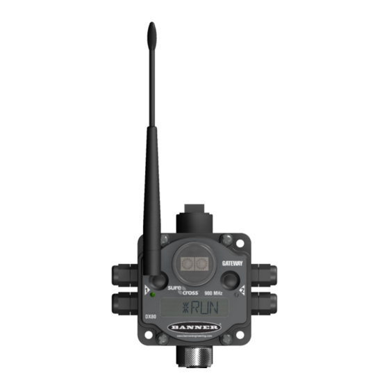
® Sure Cross Performance DX80 Wireless I/O Networks The GatewayPro has no serviceable parts inside the housing and no wiring chamber. During setup or standard operation, there should not be a need to open the GatewayPro. 2.3 DX80 GatewayPro The GatewayPro has many of the same features as the Gateway and Node, including the LEDs, the buttons, LCD, and Euro-style connector. -
Page 9: Wiring Diagrams
® Sure Cross Performance DX80 Wireless I/O Networks 2.5 Wiring Diagrams Use the following drawings to correctly wire power and I/O to the SureCross Wireless radio devices. For more information Sensor Connections . about wiring sensors to the SureCross devices, refer to 2.5.1 Apply Power to the Gateway or Node Integral 5-pin M12/Euro-style quick disconnect wiring depends on the model and power requirements of the device. -
Page 10: Dimensions
® Sure Cross Performance DX80 Wireless I/O Networks 2.6 Dimensions The DX80, DX83, and DX70 models all share the same housing and mounting hole dimensions. 2.6.1 Gateways and Nodes 65.0 22.2 [2.56”] [0.875”] [0.31”] 30.65 [1.21”] 80.3 65.0 [3.16”] [2.56”] [5”] [0.75”] 7.65... -
Page 11: Gatewaypro
® Sure Cross Performance DX80 Wireless I/O Networks DX80...E Housings 148.1 mm [5.83”] 36.2 mm [1.42”] 2X Dia 8.3 mm [0.33”] 13.7 mm [0.54”] 55.9 mm [2.20”] 6 mm [0.24”] 2X 12-14 NPSM 3.2 mm [0.13”] 75.3 mm [2.96”] 20.1 mm [0.79”] 87.6 mm [3.45”]... -
Page 12: Dx83 Ethernet Bridge
® Sure Cross Performance DX80 Wireless I/O Networks 2.6.3 DX83 Ethernet Bridge 65.0 [2.56’’] [0.31’’] [5.35’’] 65.0 80.3 [2.56’’] [3.16’’] 7.65 [0.30’’] 14.67 80.8 [0.578’’] [3.18’’] 60.0 [2.36’’] 2.6.4 DX80...E Housings 148.1 mm [5.83”] 36.2 mm [1.42”] 2X Dia 8.3 mm [0.33”] 13.7 mm [0.54”]... -
Page 13: Setting Up Your Wireless Network
® Sure Cross Performance DX80 Wireless I/O Networks 3 Setting Up Your Wireless Network To set up and install your wireless network, follow these steps. Disconnect the power from your Sure Cross devices. 1. Configure the DIP switches of all devices. For DIP switch configurations, refer to the product's datasheet. 2. -
Page 14: Apply Power To The Gateway Or Node
® Sure Cross Performance DX80 Wireless I/O Networks Sure Cross DX80 Node (150 mW radio) Sure Cross Performance Gateway (in 250 mW mode) Sure Cross Performance Node (in 250 mW mode) 3.2 Apply Power to the Gateway or Node Integral 5-pin M12/Euro-style quick disconnect wiring depends on the model and power requirements of the device. Not all Specifications to models can be powered by 10 to 30 V dc and not all models can be powered by 3.6 to 5.5 V dc. -
Page 15: Led Behavior For The Gateways
® Sure Cross Performance DX80 Wireless I/O Networks 1. Enter binding mode on the Gateway. • If you have a two-button Gateway, triple-click button 2 • If you have a one-button Gateway, triple-click the button • If you have a Gateway with no buttons, remove the rotary dial access cover and set both the right and left rotary dials to 0, then set both the right and left rotary dials to F. -
Page 16: Led Behavior For The Nodes
® Sure Cross Performance DX80 Wireless I/O Networks 900 MHz 1 Watt radios: 15 feet 2.4 GHz 65 mW radios: 1 foot LED 1 LED 2 Gateway Status Solid green Power ON Flashing red Flashing red Device Error Flashing amber Modbus Communication Active Flashing red Modbus Communication Error... -
Page 17: Conduct A Site Survey From A Gateway Board Model
® Sure Cross Performance DX80 Wireless I/O Networks 6. Examine reception readings (M, R, Y, G) of the Gateway at various locations. Site survey results display as a percentage. M represents the percent of missed packets while R, Y, and G represent the percent of received packets at a given signal strength. -
Page 18: Conduct A Site Survey Using Modbus Commands
® Sure Cross Performance DX80 Wireless I/O Networks 1. Set the Gateway's rotary dials to the Node address you'd like to conduct a Site Survey with. For example, to analyze the signal strength between this Gateway and Node 02, rotate the left rotary dial to 0 and the right rotary dial to 2. -
Page 19: Interpreting The Site Survey Results
• Adding data radios to the network to extend the range of a radio network. For more information on data radios, www.bannerengineering.com/wireless please refer to Banner’s white paper on range extension on www.bannerengineering.com - Tel: + 1 888 373 6767... -
Page 20: Improving Your Site Survey Results
The lack of signals may also be due to the distance between the Gateway (master radio) and Nodes (remote radio). If this is the case, please contact Banner Engineering for further assistance. We also recommend installing the antenna(s) remotely at a higher position. Additional antenna cables are available from Banner Engineering if needed. - Page 21 ® Sure Cross Performance DX80 Wireless I/O Networks • BWC-4MNFN3 (3 meters long) • BWC-4MNFN6 (6 meters long) • BWC-4MNFN15 (15 meters long) • BWC-4MNFN30 (30 meters long) Requires a surge suppression device (model BWC-LFNBMN-DC) if the antenna is external to a building, connected to other electronics, or elevated.
-
Page 22: Installing Your Sure Cross ® Radios
Remove Moisture and Condensation. If condensation is present in any device, add a small desiccant packet to the inside of the radio. To help vent the radios, Banner also sells a vented plug (model number BWA-HW-031) for the 1/2-inch NPT port of the SureCross radios. -
Page 23: Other Installation Requirements
To achieve the best radio performance, carefully consider the installation locations for the Gateways and Nodes and select locations without obstructions in the path. Antenna Basics reference guide, Banner document p/n 132113. For more information about antennas, please refer to the 4.3.2 Increase the Height of the Antennas... -
Page 24: Collocated Radios
® Sure Cross Performance DX80 Wireless I/O Networks 4.3.3 Collocated Radios When the radio network’s master device is located too close to another radio device, communications between all devices is interrupted. For this reason, always assign a unique Network ID to your wireless networks. The Network ID (NID) is a unique identifier you assign to each wireless network to minimizes the chances of two collocated networks interfering with each other. -
Page 25: Weatherproof Remote Antenna Installations
I/O Isolation. When connecting analog and discrete I/O to external equipment such as VFDs (Variable Frequency Drives), it may be appropriate to install interposing relays and/or loop isolation devices to protect the DX80 unit from transients, noise, and ground plane interference originating from devices or the environment. Contact Banner Engineering Corp. for more information. -
Page 26: Installing Remote Antennas
® Sure Cross Performance DX80 Wireless I/O Networks 4.4.2 Installing Remote Antennas Install and properly ground a qualified surge suppressor when installing a remote antenna system. Remote antenna configurations installed without surge suppressors invalidate the manufacturer's warranty. Keep the ground wire as short as possible and make all ground connections to a single-point ground system to ensure no ground loops ®... -
Page 27: Use An N-Type, Pole-Mounted Antenna
® Sure Cross Performance DX80 Wireless I/O Networks 4.4.4 Use an N-Type, Pole-Mounted Antenna This antenna mounts remotely from the box, with the SureCross device mounted inside the box. Ground the surge suppressor and antenna. Keep the ground wire as short as possible and make all ground connections to a single-point ground system to ensure no ground loops are created. - Page 28 ® Sure Cross Performance DX80 Wireless I/O Networks N-Type to N-Type Cables—LMR400 Type Model Length (m) Description BWC-4MNFN3 BWC-4MNFN6 LMR400 N-Type Male to N-Type Female BWC-4MNFN15 BWC-4MNFN30 BWC-LMRSFRPB BWC-LFNBMN-DC • Surge Suppressor, Bulkhead, RP- • Surge Suppressor, bulkhead, N- SMA Type Type, dc Blocking •...
-
Page 29: Advanced Setup Options
Sure Cross Performance DX80 Wireless I/O Networks 5 Advanced Setup Options ® Refer to the following sections for advanced setup instructions or additional information on Banner's Sure Cross wireless technology and its uses. 5.1 DX80 Menu Structure The Gateways and Nodes each have their own menu structure and options. - Page 30 ® Sure Cross Performance DX80 Wireless I/O Networks 5.1 DX80 Node Set-up Menu When power is applied, the DX80 begins running. The display screen auto loops through the RUN menu and communication begins between the Gateway and Node(s). Auto looping through the RUN menu is the normal operating mode for all devices on the wireless network.
-
Page 31: Run Menu
® Sure Cross Performance DX80 Wireless I/O Networks 5.1.1 RUN Menu The RUN menu displays the network ID (NID), device name (Gateway or Node), and the I/O values of the device. On the Gateway, the I/O displayed may be the I/O of the Gateway Node Gateway or of a selected Node. -
Page 32: Dinfo (Device Information) Menu
® Sure Cross Performance DX80 Wireless I/O Networks 5.1.2 DINFO (Device Information) Menu The DINFO menu displays some device-specific information. On the Gateway, the DINFO menu displays the device name, the network Gateway Node ID (NID), slave ID, baud rate, and parity. When in extended address DINFO mode, the DINFO menu also displays the maximum Node setting and the DINFO... -
Page 33: Fctry (Factory) Menu
The FCTRY menu displays the version numbers of various components within the device, including the radio micro number, the LCD number, the device’s serial number, the device’s model number, and the production date. Gateway Node If you call Banner Engineering for technical support, having this information available may help diagnose your particular FCTRY FCTRY problem. -
Page 34: Site (Site Survey) Menu
® Sure Cross Performance DX80 Wireless I/O Networks 5.1.4 SITE (Site Survey) Menu The SITE menu displays the results of a Site Survey conducted with this Gateway. Gateway The SITE menu displays the device number of the Node the Site Survey was conducted with as well as the missed, green, yellow, and red received packet SITE count. -
Page 35: Dvcfg (Device Configuration) Menu
® Sure Cross Performance DX80 Wireless I/O Networks 5.1.5 DVCFG (Device Configuration) Menu On Gateways, the DVCFG menu allows users to set various device-specific parameters, including the network ID (NID), slave ID (SLID), baud rate, and parity. In extended address mode, use this menu to also set the maximum number of radio devices (MAXN) within the network and the extended address binding code (XADR). -
Page 36: Derr (Device Error) Menu
® Sure Cross Performance DX80 Wireless I/O Networks Node DVCFG Device Config. Single-click Button 2 Single-click Button 1 to advance through menu (NID) (NADR) (XADR) Network ID Node Address Extended Addressing Single-click Single-click Single-click Button 2 Button 2 Button 2 Single-click AUTO Button 2... -
Page 37: Web-Based Configuration For The Gatewaypro On Dx83
® Sure Cross Performance DX80 Wireless I/O Networks On the Gateway use the DERR menu to clear, disable, or ignore error messages generated by devices within the network. The Node number that generated the error and the error code (EC) display onscreen. Single-click button 1 to advance through the menu of CLEAR (clear this particular instance of the error from the system), DISABL (disable this particular error from appearing from this specific Node), and IGNORE (ignore this error but do not remove it from the system). -
Page 38: Accessing The Web-Based Configuration Screens
PC with an IP address different from the Ethernet Bridge or GatewayPro IP addresses. (Refer to Banner document p/n 133116 for detailed instructions on setting up the host computer’s network IP address.) For example, change the PC host IP address to: 192.168.0.2. To access the configuration screens, follow these steps. -
Page 39: Changing The Ip Address
® Sure Cross Performance DX80 Wireless I/O Networks 5.2.2 Changing the IP Address Use the page tabs at the top of the page to select the hierarchical path: System > Setup > Network . To change the IP address, type in the new IP address and click the Change IP button. The IP address change activates when the Ethernet Bridge or GatewayPro reboots (cycles power). -
Page 40: Bind Radios Using Modbus Commands
® Sure Cross Performance DX80 Wireless I/O Networks 4. On the Gateway, single click button 1 to advance across the menus, stopping at the DVCFG menu. The Gateway's LCD displays (DVCFG). 5. Single click button 2 to select DVCFG. Single click button 1 to select from the available menu options, stopping at XADR. -
Page 41: Setting The Network Id In Extended Addressing Mode
® Sure Cross Performance DX80 Wireless I/O Networks 2. Enter binding mode on the Node. • If you have a two-button Node, triple-click button 2. • If you have a one-button Node, triple-click the button. • If you have a Node with no buttons, remove the top cover and set both the left and right rotary dials to F to enter binding mode. -
Page 42: Manually Assign A Binding Code To A Node
® Sure Cross Performance DX80 Wireless I/O Networks 4. Single click button 2 to enter the XADR menu. AUTO is automatic binding mode and uses the Gateway’s serial number as the binding code. 5. Single click button 1 to select manual mode. 6. -
Page 43: Setting The Maximum System Devices
® Sure Cross Performance DX80 Wireless I/O Networks 5.7 Setting the Maximum System Devices To set the maximum number of devices in your system, use the MAXN submenu, located under the *DVCFG (Device Configuration) menu. Selecting the maximum number of system radio devices (Gateway and all Nodes) changes the timing for the wireless network. -
Page 44: Modbus Communication Parameters
® Sure Cross Performance DX80 Wireless I/O Networks 5.10 Modbus Communication Parameters To access the Modbus device, you may first need to configure system-level communication parameters on the Gateway. The following procedures are necessary to change the Gateway's slave ID, baud rate, and parity. Setting up the Network and Device IDs, powering up the devices, and conducting the Site Survey for a host-connected network is the same as for the non-host DX80 or DX80 Performance wireless system. -
Page 45: Set The Parity
® Sure Cross Performance DX80 Wireless I/O Networks 7. Double-click Gateway push button 2 to return to the Device Configuration (*DVCFG) menu. 8. Click Gateway push button 1 until reaching the *RUN menu option. 5.10.3 Set the Parity Parity bits are used to detect errors in data. 1. -
Page 46: Gateway Link Failure
Gateway can clear the error condition and resume normal operation. The front panel buttons or the Gateway’s register I/O 15 clear error conditions. Clearing a lost radio link error does not restore communications. Banner recommends determining and resolving the cause of the radio link error, then allowing the system to auto-recover the lost communications. -
Page 47: Defining The Units
Unsigned values range from 0 to 65535 and are used to measure values that do not go below zero, such as 4 to 20 mA, distance, or a counter. 5.12.1 Interpreting Register Values in the Banner Wireless System The units conversion table defines the type and range of values for each type of I/O. -
Page 48: Product Support And Maintenance
® Sure Cross Performance DX80 Wireless I/O Networks 6 Product Support and Maintenance 6.1 DX80 Performance Documentation For additional information, including installation and configuration, weatherproofing, device menu maps, troubleshooting, and a list of accessories, refer to one of the following product manuals. 128185 •... -
Page 49: Led Message Codes
® Sure Cross Performance DX80 Wireless I/O Networks 6.2.2 LED Message Codes Solid or flashing LEDs mean different things depending on whether the device is a Gateway, GatewayPro, Node, or DX85 Remote I/O Modbus Slave. LED 1 LED 2 Definition/Solution Solid green Gateway, DX85: Power is on Flashing green... -
Page 50: Lcd Message Codes
® Sure Cross Performance DX80 Wireless I/O Networks 6.2.3 LCD Message Codes These message codes display on the device's LCD. Message Solution BAD EE System Error. A system error typically represents a failure of the EE PROM. Contact the factory for replacement. The XX refers to the Modbus register 8 message code shown in Modbus Message Codes for Register 8 on page... -
Page 51: Inputs And Outputs
When a specific Node/Gateway radio link fails, all pertinent wired outputs are de-energized until the link is recovered (see component datasheet for more information.) Through this process, users of Banner wireless networks can be assured that disruptions in the communications link result in predictable system behavior. -
Page 52: Maintenance
® Sure Cross Performance DX80 Wireless I/O Networks OUT 1 = Normal OUT 2 = Normal OUT 1 = Normal Node 1 OUT 2 = Normal OUT 3 = Normal OUT 4 = Normal Gateway OUT 1 = Normal OUT 2 = Normal Node 2 Figure 6. - Page 53 Potential electrostatic charging hazard — only clean with a damp cloth. • The replacement battery MUST be a Banner approved battery, model number BWA-BATT-001. Use of a different battery will VOID the intrinsic safety rating of this device and may result in an explosion! •...
- Page 54 Do not replace battery when an explosive dust atmosphere may be present. • The replacement battery MUST be a Banner approved battery, model number BWA-BATT-001. Use of a different battery will VOID the intrinsic safety rating of this device and may result in an explosion! •...
-
Page 55: Sure Cross ® Radio Certifications
® 6.4 Sure Cross Radio Certifications Banner's Sure Cross product line is certified by the FCC, European Union, and many other countries for operation within specific radio frequencies. 6.4.1 FCC Certification, 900 MHz, 1 Watt Radios The DX80 Module complies with Part 15 of the FCC rules and regulations. -
Page 56: Fcc Certification, 2.4Ghz
When using other antennas, verify you are not exceeding the transmit power levels allowed by local governing agencies. This device has been designed to operate with the antennas listed on Banner Engineering’s website and having a maximum gain of 9 dBm. Antennas not included in this list or having a gain greater that 9 dBm are strictly prohibited for use with this device. -
Page 57: Glossary Of Wireless Terminology
® Sure Cross Performance DX80 Wireless I/O Networks 6.5 Glossary of Wireless Terminology This definitions list contains a library of common definitions and glossary terms specific to the Wireless products. active threshold An active threshold is a trigger point or reporting threshold for an analog input. a/d converter An analog to digital converter converts varying sinusoidal signals from instruments into binary code for a computer. - Page 58 ® Sure Cross Performance DX80 Wireless I/O Networks Something has changed data channel A channel may be either a path for communications or a range of radio frequencies used by a transceiver during communication. collision A collision is a situation in which two or more transmissions are competing to communicate on a system that can only handle one transmission at a time.
- Page 59 ® Sure Cross Performance DX80 Wireless I/O Networks Another decibel rating, dBi, is defined as an antenna’s forward gain compared to an idealized isotropic antenna. Typically, dBm = dBi = dBd + 2.15 where dBi refers to an isotropic decibel, dBd is a dipole decibel, and dBm is relative to milliwatts.
- Page 60 ® Flex Power Flex Power Banner’s technology allows for a true wireless solution by allowing the device to operate using either 10 to 30 V dc, 3.6 V lithium D cell batteries, or solar power. This unique power management Flex Power Node and an optimized sensing device for up to 5 years on a single system can operate a lithium D cell.
- Page 61 ® Sure Cross Performance DX80 Wireless I/O Networks 3rd Fresnel Zone 2nd Fresnel Zone 1st Fresnel Zone gain Gain represents how well the antenna focuses the signal power. A 3 dB gain increase doubles the effective transmitting power while every 6 dB increase doubles the distance the signal travels. Increasing the gain sacrifices the vertical height of the signal for horizontal distance increases.
- Page 62 ® Sure Cross Performance DX80 Wireless I/O Networks ON point Threshold Hysteresis Input OFF point Time Industrial, The ISM, or Industrial, Scientific, and Medical band, is the part of the radio spectrum that does not Scientific, and require a license for use. The Sure Cross radios operate in the ISM band. Medical Band (ISM) latency...
- Page 63 A node is any communications point within a network. Node Nodes are remote I/O slave devices within Banner's wireless sensor networks. Sensors and other devices connect to the Node's inputs or outputs, allowing the Node to collect sensor data and wirelessly transmit it to the Gateway.
- Page 64 ® Sure Cross Performance DX80 Wireless I/O Networks Node, the Gateway generates an RF timeout error in the Modbus I/O register 8 of the appropriate Node. The ‘Maximum Misses’ is defined as the number of consecutive polling messages that the Node fails to respond to.
- Page 65 ® Sure Cross Performance DX80 Wireless I/O Networks sample on Sample on demand allows a host system to send a Modbus command to any register and require the demand inputs to immediately sample the sensor and report readings back to the host system. Sampling on demand can be used between the normal periodic reporting.
- Page 66 ® Sure Cross Performance DX80 Wireless I/O Networks Sure Cross Performance DX80 For more information on Banner's star network products, refer to the Wireless I/O Network Instruction Manual (p/n 132607 Flex Power devices to include an internal power switch power...
-
Page 67: Contact Us
Shintaro Uda and Hidetsugu Yagi, both of Tohoku Imperial University in Sendai, Japan. Yagi antennas may also be called beam antennas or directional antennas. 6.6 Contact Us Banner Engineering Corporate headquarters is located at: 9714 Tenth Avenue North Minneapolis, MN 55441, USA www.bannerengineering.com... -
Page 68: Warnings
When using other antennas, verify you are not exceeding the transmit power levels allowed by local governing agencies. This device has been designed to operate with the antennas listed on Banner Engineering’s website and having a maximum gain of 9 dBm. Antennas not included in this list or having a gain greater that 9 dBm are strictly prohibited for use with this device. - Page 69 Index polling 51 forming networks 14 antenna fullscale 47 increase height 23 installing 24 radio link failure 51 installing dome 26 radio time-out 50, 51 installing N-type 27 RF device time-out 50 gasket installing remote 24–27 main body 52 weatherproofing 25 ground 23 ground wire 24–27 seasonal changes 24...
Need help?
Do you have a question about the Sure Cross DX80 Series and is the answer not in the manual?
Questions and answers