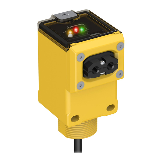
Banner Q45 Quick Start Manual
Sensor networks formed using the -qc gateway
Hide thumbs
Also See for Q45:
- Quick start manual (2 pages) ,
- Quick start manual (5 pages) ,
- Setup manual (12 pages)
Advertisement
Quick Start Guide for Wireless Q45 Sensor Networks
Formed Using the -QC Gateway
Each sensor is mapped to the one of the Gateway's outputs by
default. Other mapping options are also supported.
Each wireless network may have up to six Wireless Q45 Sensor optical models (default configuration) when using the DX80G2M6S-Q
Gateway's DIP switch-based mapping.
Each Wireless Q45 Sensor is mapped to one of the Gateway's six discrete outputs.
Step 1: Wire the Gateway's Outputs
To wire the Gateway's outputs:
1. Remove the four screws holding the radio cover to the housing base.
2. Wire your outputs according to your network's configuration.
For additional configuration and Gateway wiring options, refer to the Gateway with Switch Mapping datasheet, part number 161862. To
use more than six sensors (up to 47) in the wireless network, use a Modbus host system (see the Host Configuration manual, Banner p/n
134112).
Use this wiring diagram for the default configuration for Optical Sensor Models: six Q45 Sensors mapped to the six Gateway outputs.
DI1
DI2
DI3
DI4
DI5
DI6
V+
V-
V-
Printed in USA
Q45 1
Q45 2
Q45 3
DO1
Q45 1
DO2
Q45 2
DO3
Q45 3
DO4
Q45 4
DO5
Q45 5
DO6
Q45 6
Tx/+
Rx/-
V+
Gateway Model
DX80G2M6-QC
Gateway
outputs 1-6
To GND
Load
Load
Load
Load
Load
Load
May 2012
Q45 4
Q45 5
Q45 6
P/N 159359 rev. A
Advertisement
Table of Contents

Summary of Contents for Banner Q45
- Page 1 For additional configuration and Gateway wiring options, refer to the Gateway with Switch Mapping datasheet, part number 161862. To use more than six sensors (up to 47) in the wireless network, use a Modbus host system (see the Host Configuration manual, Banner p/n 134112).
- Page 2 2. On the Gateway, use both rotary dials to assign the Node address for the Q45. Use the left dial for the left digit and the right dial for the right digit. For example, to assign your Q45 to Node 01, set the left dial to 0 and the right dial to 1.


Need help?
Do you have a question about the Q45 and is the answer not in the manual?
Questions and answers