Banner SureCross DX80 Product Manual
Hide thumbs
Also See for SureCross DX80:
- Network manual (110 pages) ,
- Reference manual (96 pages) ,
- Product manual (42 pages)
Table of Contents
Advertisement
Advertisement
Table of Contents
Troubleshooting

Related Manuals for Banner SureCross DX80


Summary of Contents for Banner SureCross DX80
- Page 1 SureCross DX80 and Performance DX80 Product Manual Rev. J 9/18/2013 132607...
-
Page 2: Table Of Contents
Contents Contents ® 1 The SureCross Performance Wireless Network ............. 5 1.1 SureCross ® Performance Gateways and Nodes ................5 1.2 SureCross ® Performance GatewayPro ..................5 1.3 DX83 Ethernet Bridge Overview ....................5 1.4 Host Controller Systems ......................6 ® 1.5 What is FlexPower ......................... - Page 3 ...................... 46 5.8.3 Node Link Failure ......................47 5.9 Units Defined ..........................47 5.9.1 Interpreting Register Values in the Banner Wireless System ..........49 5.10 Setting up the Wireless Network Using the Rotary Dials .............. 52 5.10.1 Rotary Dial Address Mode ..................... 52 5.10.2 Setting the Network ID Using the Rotary Dials...
- Page 4 ................101 12.3 FCC Certification, 2.4GHz ......................102 12.4 Certified For Use in the Following Countries ................103 12.5 Exporting SureCross Radios ....................105 13 Warnings ......................... 106 13.1 Banner Engineering Corp Limited Warranty ................106 13.2 Contact Us ......................... 106 Rev. J...
-
Page 5: The Surecross ® Performance Wireless Network
® 1 The SureCross Performance Wireless Network ® The SureCross Performance wireless I/O network provides reliable monitoring without wiring or conduit installation. The SureCross wireless network operates independently or in con- junction with a host system, PLC, and/or PC software. Each wireless network system consists of one Gateway and Node one or more Nodes. -
Page 6: Host Controller Systems
1.5 What is FlexPower Banner’s FlexPower technology supplies a true wireless solution by allowing the device to operate using either 10–30V dc, 3.6V lithium D cell batteries, or solar power. This unique power management system can operate a FlexPower Node and an optimized sensing device for up to five years on a single lithium D cell. -
Page 7: Surecross User Configuration Tool
SureCross DX80 and Performance DX80 Product Manual DX81: Single battery supply module DX81P6: Six-pack battery supply mod- BWA-SOLAR-001: Solar supply; in- cludes solar panel, rechargeable bat- DX81H: Single battery supply module teries, and controller. designed specifically to power the DX99 Intrinsically Safe devices with polycarbonate housings 1.6 SureCross User Configuration Tool... -
Page 8: Features
SureCross DX80 and Performance DX80 Product Manual 2 Features The following feature callouts refer to the DX80 Gateway and Node models, the GatewayPro, and the DX83 Ethernet Bridge. The wiring diagrams include information for connection power and sensors using the 5-pin Euro-style connect, the terminal wiring board, and the Industrial Ethernet connection on the DX83 and GatewayPro. -
Page 9: Dx80 Gatewaypro
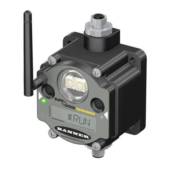
SureCross DX80 and Performance DX80 Product Manual 1. Housing. The rugged, industrial DX80 housing meets IEC IP67 standards. 2. Mounting hold, #10/M5 clearance. Mounting Holes accept metric M5 or UNC/UNF #10 hardware -- DIN rail mount adapt- er bracket available. -
Page 10: Wiring Diagrams
SureCross DX80 and Performance DX80 Product Manual 1. Industrial ethernet port, female. 2. Housing. The rugged, industrial DX80 housing meets IEC IP67 standards. 3. Mounting hold, #10/M5 clearance. Mounting Holes accept metric M5 or UNC/UNF #10 hardware -- DIN rail mount adapter bracket available. -
Page 11: Dx80
SureCross DX80 and Performance DX80 Product Manual 2.5.3 DX80...C Wiring Wiring power to the DX80...C models varies depending the power requirements of the model. Connecting dc power to the communication pins (Tx/Rx) causes permanent damage. For FlexPower devices, do not apply more than 5.5V to the B+ terminal. - Page 12 SureCross DX80 and Performance DX80 Product Manual 65.0 22.2 [2.56”] [0.875”] [0.31”] 30.65 [1.21”] 65.0 80.3 [2.56”] [3.16”] [0.75”] [5”] 7.65 [0.30”] [2.36”] 14.67 [0.578”] 80.8 [3.18”] [4.72”] DX80...C Gateways and Nodes The DX80...C and Performance DX80...C Gateways and Nodes have the same external and mounting dimensions.
-
Page 13: Gatewaypro
SureCross DX80 and Performance DX80 Product Manual 195.9 mm [7.71’’] 148.1 mm [5.83’’] 87.6 mm [3.45’’] 55.9 mm [2.20’’] For 1/4” or M7 bolts 20.1 mm [0.79’’] 59.7 mm [2.35”] 2.6.2 GatewayPro The DX80 and Performance DX80 GatewayPro has the same external and mounting dimensions as the Gateway and Node, but does not have any side access holes or glands. -
Page 14: Dx83 Ethernet Bridge
SureCross DX80 and Performance DX80 Product Manual 2.6.3 DX83 Ethernet Bridge Like the GatewayPro, the DX83 Ethernet Bridge has the same external and mounting dimensions, but no side access holes or glands. 65.0 [2.56’’] [0.31’’] [5.35’’] 65.0 80.3 [2.56’’] [3.16’’] 7.65... -
Page 15: Setting Up Your Wireless Network
Non-Performance radios must be set to use Extended Address Mode (DIP switch 1 ON) For more detailed instructions about setting up your wireless network, refer to the Quick Start Guide, Banner document number 128185. For more information about using Performance and non-Performance radios within the same network, re- fer the technical note titled Mixing Performance Radios and 150 mW Radios in the Same Networklisted on the FAQ/Knowl- edgebase section of Banner's Wireless Sensor Networks website. -
Page 16: Applying Power To The Gateway Or Node
SureCross DX80 and Performance DX80 Product Manual 3.3 Applying Power to the Gateway or Node Wire Color Gateway (10–30V Node (10–30V dc) Node (FlexPower) brown 10–30V dc input 10–30V dc white RS485 / D1 / B / + blue dc common (GND) -
Page 17: Led Behavior For The Gateways
SureCross DX80 and Performance DX80 Product Manual Valid Network IDs are 01 through 32, in decimal, established using both rotary dials. The left dial may be set to 0, 1, 2, or 3. The right dial may be set from 0 to 9 when the left dial is at 0, 1, or 2; or set to 0 through 2 when the left dial is at 3. -
Page 18: Conducting A Site Survey Using Modbus Commands
SureCross DX80 and Performance DX80 Product Manual 3. Single-click button 1 to scroll across the menu levels until reaching the Site Survey (SITE) menu. 4. Single-click button 2 to enter the Site Survey menu. 5. Single-click button 2 to begin conducting a Site Survey with the Node selected in step 2. -
Page 19: Interpreting The Site Survey Results
SureCross DX80 and Performance DX80 Product Manual The Gateway device also displays the Site Survey results on the LCD. For one transmit and receive interval, the Gateway saves the lowest signal strength. The LCD and Modbus registers contain the results of the last 100 samples. The totals are a running tally of the last 100 samples and are continuously updated. -
Page 20: Site Survey Troubleshooting
Higher gain antennas focus the energy of the radio signal in a specific direction and extend the signal’s range. Using data radios is another option to consider when trying to extend the range of a radio network. For more information on data radios, please refer to Banner’s white paper on range extension on www.bannerengineer- ing.com/surecross. -
Page 21: Installing Your Surecross ® Radios
Remove Moisture and Condensation. If condensation is present in any de- vice, add a small desiccant packet to the inside of the radio. To help vent the ra- dios, Banner also sells a vented plug (model number BWA-HW-031) for the 1/2- inch NPT port of the SureCross radios. -
Page 22: Other Installation Requirements
To achieve the best radio performance, carefully consider the installation locations for the Gateways and Nodes and se- lect locations without obstructions in the path. For more information about antennas, please refer to the Antenna Basics reference guide, Banner document p/n 132113. 4.3.2 Increase the Height of the Antennas Position the external antenna vertically for optimal RF communication. -
Page 23: Collocated Radios
SureCross DX80 and Performance DX80 Product Manual 4.3.3 Collocated Radios When the radio network’s master device is located too close to another radio device, communications between all devices is interrupted. For this reason, always assign a unique Network ID to your wireless networks. The Network ID (NID) is a unique identifier you assign to each wireless network to minimizes the chances of two collocated networks interfering with each other. -
Page 24: Weatherproof Remote Antenna Installations
I/O Isolation. When connecting analog and discrete I/O to external equipment such as VFDs (Variable Frequency Drives), it may be appropriate to install interposing relays and/or loop isolation devices to protect the DX80 unit from tran- sients, noise, and ground plane interference originating from devices or the environment. Contact Banner Engineering Corp. for more information. -
Page 25: Antenna Installation
SureCross DX80 and Performance DX80 Product Manual 4.4.2 Antenna Installation Antenna Installations. Install and properly ground a qualified surge suppressor when installing a remote antenna sys- tem. Remote antenna configurations installed without surge suppressors invalidate the manufacturer's warranty. Keep the ground wire as short as possible and make all ground connections to a single-point ground system to ensure no ground loops are created. - Page 26 SureCross DX80 and Performance DX80 Product Manual 5, 6 7, 8 Model Number Description BWA-9O2-C Antenna, Omni, 902-928 MHz, 2 dBd, Rubber Swivel, RP-SMA MALE BWA-9O5-C Antenna, Omni, 902-928 MHz, 5 dBd, Rubber Swivel, RP-SMA MALE BWA-2O2-C Antenna, Omni, 2.4 GHz, 2 dBd, Rubber Swivel, RP-SMA MALE BWA-2O5-C Antenna, Omni, 2.4 GHz, 5 dBd, Rubber Swivel, RP-SMA MALE...
-
Page 27: Mounting N-Type Antennas Remotely
SureCross DX80 and Performance DX80 Product Manual Model Number Description DX81P6 DX81P6 FlexPower Battery Supply 6-Pack 4.4.5 Mounting N-Type Antennas Remotely This antenna mounts remotely from the box, with the SureCross device mounted inside the box. This configuration may be used either inside or outside the building, though a Yagi antenna is usually used in outdoors ap- plications while an omni-directional antenna may be used either inside or outside a building. - Page 28 SureCross DX80 and Performance DX80 Product Manual Model Number Description BWA-EF14128 Fiberglass enclosure, 14”x 12” x 8” BWA-PA1412 Internal panel, 14” x 12” DX81 DX81 FlexPower Battery Supply Module DX81P6 DX81P6 FlexPower Battery Supply 6-Pack 3 This example image depicts a DX80 radio with a +10–30V dc power supply. The example installation may also work with the DX70 radios or MultiHop radios.
-
Page 29: Advanced Setup Instructions And Additional Information
5 Advanced Setup Instructions and Additional Infor- mation Refer to the following sections for advanced setup instructions or additional information on Banner's SureCross wireless technology and its uses. 5.1 DX80 Menu Structure The Gateways and Nodes each have their own menu structure and options. - Page 30 SureCross DX80 and Performance DX80 Product Manual 5.1 DX80 Node Set-up Menu When power is applied, the DX80 begins running. The display screen auto loops through the RUN menu and communica- tion begins between the Gateway and Node(s). Auto looping through the RUN menu is the normal operating mode for all devices on the wireless network.
- Page 31 SureCross DX80 and Performance DX80 Product Manual Press and hold Button 1 from any top level menu to power down the Node. Press and hold Button 1 from power down mode to enter RUN mode. Single-click Button 1 to advance through menu...
-
Page 32: Run Menu
SureCross DX80 and Performance DX80 Product Manual 5.1.1 RUN Menu The RUN menu displays the network ID (NID), device name (Gateway or Node), and the I/O values of the device. Gateway Node On the Gateway, the I/O displayed may be the I/O of the Gateway or of a selected Node. -
Page 33: Dinfo (Device Information) Menu
SureCross DX80 and Performance DX80 Product Manual 5.1.2 DINFO (Device Information) Menu The DINFO menu displays some device-specific information. Gateway Node On the Gateway, the DINFO menu displays the device name, the net- work ID (NID), slave ID, baud rate, and parity. When in extended ad-... -
Page 34: Fctry (Factory) Menu
The FCTRY menu displays the version numbers of various components within the device, including the radio micro number, the LCD number, the device’s serial number, the device’s model number, and the production date. Gateway Node If you call Banner Engineering for technical support, having this information available may help diagnose your particular FCTRY FCTRY problem. -
Page 35: Site (Site Survey) Menu
SureCross DX80 and Performance DX80 Product Manual 5.1.4 SITE (Site Survey) Menu Access the SITE menu to see the results of a Site Survey conducted with this Gateway. Gateway The SITE menu displays the device number of the Node the... -
Page 36: Dvcfg (Device Configuration) Menu
SureCross DX80 and Performance DX80 Product Manual 5.1.5 DVCFG (Device Configuration) Menu On Gateways, the DVCFG menu allows users to set various device-specific parameters, including the network ID (NID), slave ID (SLID), baud rate, and parity. In extended address mode, use this menu to also set the maximum number of radio devices (MAXN) within the network and the extended address binding code (XADR). -
Page 37: Derr (Device Error) Menu
SureCross DX80 and Performance DX80 Product Manual Node DVCFG Device Config. Single-click Button 2 Single-click Button 1 to advance through menu (NID) (NADR) (XADR) Network ID Node Address Extended Addressing Single-click Single-click Single-click Button 2 Button 2 Button 2 Single-click... -
Page 38: Web-Based Configuration
SureCross DX80 and Performance DX80 Product Manual On the Gateway use the DERR menu to clear, disable, or ignore error messages generated by devices within the net- work. The Node number that generated the error and the error code (EC) display onscreen. Single-click button 1 to ad- vance through the menu of CLEAR (clear this particular instance of the error from the system), DISABL (disable this partic- ular error from appearing from this specific Node), and IGNORE (ignore this error but do not remove it from the system). -
Page 39: Accessing The Web-Based Configuration Screens
SureCross DX80 and Performance DX80 Product Manual 1. Ethernet crossover cable using the Modbus/TCP or ™ EtherNet/IP communication protocol 2. Industrial Ethernet connection Host 3. GatewayPro 5.2 Example Layout #3 This example system layout may also be configured using the web pages. Instead of using a GatewayPro to connect to the host system, a Gateway and Ethernet Bridge is used to achieve the same function. -
Page 40: Changing The Ip Address
SureCross DX80 and Performance DX80 Product Manual The Web home page for the Ethernet Bridge or GatewayPro displays. 2. Click on any tab at the top of page to log into the configuration software. 3. Enter system as the user name and admin as the password. -
Page 41: Binding Mode: What Does It Do
SureCross DX80 and Performance DX80 Product Manual 5.3 Binding Mode: What does it do? Binding Nodes to a Gateway ensures the Nodes only exchange data with the Gateway they are bound to. After a Gateway enters binding mode, the Gateway automatically generates and transmits a unique extended addressing (XADR), or bind- ing, code to all Nodes within range that are also in binding mode. -
Page 42: Manually Choosing An Extended Address (Binding) Code - Node
SureCross DX80 and Performance DX80 Product Manual After reaching the sixth digit, the curser returns to the first digit. 12. Single click button 2 when code entry is complete. The Gateway LCD displays the entered value for confirmation by showing CONFRM XADR, then repeating back your val- 13. -
Page 43: Automatic Binding Using The Menu Navigation
SureCross DX80 and Performance DX80 Product Manual 4. Using both rotary dials on the Gateway, select a Network ID. The left rotary dial acts as the left digit and the right rota- ry dial acts as the right digit of the Network ID. In extended addressing mode, the Network ID can only be set from the rotary dials while in the (NID) menu. -
Page 44: Setting The Maximum System Devices
SureCross DX80 and Performance DX80 Product Manual For devices with batteries integrated into the housing, remove the battery for one minute to cycle power to the device. After making any changes to DIP switch settings, you must cycle power to the device or the DIP switch changes will not be recognized. -
Page 45: Setting The Baud Rate
SureCross DX80 and Performance DX80 Product Manual To avoid losing the network connection between the Gateway and Nodes, reset the rotary switches back to their appro- priate values before leaving the *DVCFG sub-menus. If the Gateway and Nodes lose their connection, the network may take up to 20 seconds to re-synchronize. -
Page 46: Gateway Link Failure
SureCross DX80 and Performance DX80 Product Manual Host System Node 1 Gateway Node 2 5.8.2 Gateway Link Failure Gateway link failures are determined by three global parameters: polling interval, maximum missed message count, and re-link count. The polling interval (or rate) defines how often the Gateway communicates with each Node to verify the radio link is op- erating. -
Page 47: Node Link Failure
Gateway’s register I/O 15 clear error conditions. Clearing a lost radio link error does not restore communications. Banner recommends determining and resolving the cause of the radio link error, then allowing the system to auto-recover the lost communications. - Page 48 SureCross DX80 and Performance DX80 Product Manual Units Description Definition Temp °F Fahrenheit, high resolution. Analog input for temperature devices such as thermocouples, RTD, and thermistors. In high resolution mode, temperature = (Modbus register value) ÷ 20. LCD: 0000.0F Temp °C (Low Celsuis, low resolution.
-
Page 49: Interpreting Register Values In The Banner Wireless System
4 mA. The span is the entire distance range that is to be associated with 4 to 20 mA. LCD: 4.00mA–20.00mA 5.9.1 Interpreting Register Values in the Banner Wireless System The units conversion table defines the type and range of values for each type of I/O. - Page 50 SureCross DX80 and Performance DX80 Product Manual Holding Register I/O Range Representation Input Type Data Conversion Description Min. Max. Min. Max. Linear mapping of un- (20 mA ÷ 65535) × Reg 0–20 mA 0.0 mA 20.0 mA 65535 signed register value to...
- Page 51 SureCross DX80 and Performance DX80 Product Manual Register Value Converted Decimal Calculated Temperature Two's Complement Val- Decimal Value (Converted Decimal ÷ 20) 0000 0000 0000 0010 0.10 0000 0000 0000 0001 0.05 0000 0000 0000 0000 1111 1111 1111 1111 65535 -0.05...
-
Page 52: Setting Up The Wireless Network Using The Rotary Dials
SureCross DX80 and Performance DX80 Product Manual Example: Distance Map Map a distance input from a Node to a 0–10V output. The starting distance is 200 mm and the last distance will be 2000 mm (4 mA = 200 mm and 20 mA = 2000 mm). This defines the null as 200 and the span as 1800. -
Page 53: Setting The Device Address Using The Rotary Dials
SureCross DX80 and Performance DX80 Product Manual 5.10.3 Setting the Device Address Using the Rotary Dials The Device ID establishes a unique identifier for each device within a wireless network. 1. On the Gateway, set the right rotary dial to 0. - Page 54 SureCross DX80 and Performance DX80 Product Manual Apply power to the Gateway The LCD displays the text shown. While Channel Search Mode runs, LED 1 is solid START red and LED 2 flashes yellow. CHANNL SEARCH MODE The device tests Network ID 2 for availability...
-
Page 55: System Layouts
6 System Layouts Because of the flexibility of the DX80 wireless devices, many different configurations using Gateways, Nodes, Gateway- Pros, Ethernet Bridges, Modbus slave devices, data radios, data radio repeaters, and/or solar powered systems are possi- ble, both as stand-alone systems and host-connected systems. DX83 Ethernet Bridge DX80 Gateway, 900 MHz DX80DR9M-H MultiHop Radio... -
Page 56: Gateway With Multiple Nodes (Dx80)
SureCross DX80 and Performance DX80 Product Manual 6.1.2 Gateway with Multiple Nodes (DX80) In this configuration, the Gateway is the master of the wireless network. Configure this network using the User Configuration Tool (UCT) and RS-485 to USB adapter cable. The UCT is used to map inputs and outputs between Nodes and Gateways. -
Page 57: Gateway Configured As A Modbus Master
SureCross DX80 and Performance DX80 Product Manual 6.1.3 Gateway Configured as a Modbus Master This example network uses the Gateway as master of the wireless network and master of the Modbus network. This configuration is used when the I/O capacity of the Gateway is exceeded. -
Page 58: Modbus Rtu
SureCross DX80 and Performance DX80 Product Manual 6.2 Modbus RTU 6.2.1 Modbus RTU Host Controlled Operation A simple host-connected system uses an RS-485 serial cable to connect the Gateway to a host system. The host system may be a PC or a PLC unit. Because the serial cable is used to connect to a host system, the communica- tions protocol used is Modbus RTU. -
Page 59: Modbus Rtu With Multiple Slave Devices
SureCross DX80 and Performance DX80 Product Manual 6.2.2 Modbus RTU with Multiple Slave Devices In the example host controlled configuration, the Gateway is a Modbus slave to the host system, but remains the master of the wireless network. The Gateway is connected directly to the host system using an RS-485 serial cable. This system may also connect DX85 Modbus RTU Remote I/O devices to the serial cable to expand the available I/O. -
Page 60: Modbus Rtu With Multiple Slave Devices - Layout 2
SureCross DX80 and Performance DX80 Product Manual 6.2.3 Modbus RTU with Multiple Slave Devices - Layout 2 In this example host controlled configuration, the Gateway is a Modbus slave to the host system, but remains the master of the wireless network. -
Page 61: Modbus/Tcp And Ethernet/Ip
SureCross DX80 and Performance DX80 Product Manual 6.3 Modbus/TCP and EtherNet/IP 6.3.1 Host Connected - DX80 GatewayPro Connect a GatewayPro to a host system using the GatewayPro's industrial Ethernet connection. To connect the GatewayPro directly to the host system, use a crossover cable. By default, the GatewayPro is a ™... - Page 62 SureCross DX80 and Performance DX80 Product Manual www.bannerengineering.com - tel: 763-544-3164 Rev. J...
-
Page 63: Data Radios
SureCross DX80 and Performance DX80 Product Manual 6.4 Data Radios 6.4.1 Data Radios Data radios extend the range of the Modbus network and keep the network addressing system simple. In this basic example, the data radios act as a wire replacement to extend the Modbus network. -
Page 64: Data Radios With A Gateway As The Modbus Master
SureCross DX80 and Performance DX80 Product Manual 6.4.3 Data Radios with a Gateway as the Modbus Master In this example network, the Gateway is both the master for the radio network and the master for the Modbus network. The DX85 shown is a Modbus slave; the data radios extend the range of the Modbus network. -
Page 65: Sensor Connections
7 Sensor Connections The Sensor Connections guide lists most common Banner and non-Banner sensors and how to wire them to the DX80 devices. This reference guide lists typical connections. If you have additional questions about a specific sensor or its connection in- structions, please contact Banner Engineering or the manufacturer of the sensor you are using. -
Page 66: Discrete Inputs, Mini-Beam
Analog Sensors. For analog sensors, the ground/dc common of the sensor should be connected to the ground of the DX80 device. For best results, Banner recommends that the power source for the sensor and DX80 device is the same. 7.3.1 Analog Inputs, Powered using SureCross Device Terminals... -
Page 67: Analog Inputs, Powered From Switch Power
SureCross DX80 and Performance DX80 Product Manual 7.3.2 Analog Inputs, Powered from Switch Power Two-Wire Sensors Three-Wire Sensors sensor − Analog IN − Analog IN − − sensor dc common dc common Two-wire analog sensor or two-wire NAMUR proximity sen- Three-wire analog sensor using a FlexPower Node and pow- sor using a FlexPower Node and powered using the Node’s... -
Page 68: Analog Inputs, Qt50U Long-Range Ultrasonic Sensor
SureCross DX80 and Performance DX80 Product Manual 7.3.5 Analog Inputs, QT50U Long-Range Ultrasonic Sensor QT50U Ultrasonic Sensor Four-wire QT50U sensor, using a FlexPower Node, and pow- ered using the Node’s switch power terminal. The QT50U (wh) output is set to 4–20 mA. -
Page 69: Surecross Power Solutions
8.2 What is FlexPower Banner’s FlexPower technology supplies a true wireless solution by allowing the device to operate using either 10–30V dc, 3.6V lithium D cell batteries, or solar power. This unique power management system can operate a FlexPower Node and an optimized sensing device for up to five years on a single lithium D cell. -
Page 70: Flexpower With Integrated Battery
8.2.3 FlexPower Solar Supply Banner’s FlexPower Solar Supply Assembly can be used to power up to two radio devices, including a FlexPower Node, a FlexPower Gateway, or a data radio. When used with a FlexPower Node and sensors, the Solar Assembly supplies enough power to run most sensors at higher sample and re- port rates than a single battery can reasonably support. -
Page 71: Discrete Configuration
For each sensor characterized, a boost voltage and warmup time was specified. The sample and reports rates were varied to calculate the estimated battery life. For example, a Banner QT50ULBQ6-75390 sensor set to a boost voltage of 15 volts, a warm-up time of 500 milliseconds, and a sample and report rate of 15 minutes, should have a battery life of 4.45 years. -
Page 72: Temperature And Humidity Sensor
For each sensor characterized, a boost voltage and warmup time was specified. The sample and reports rates were varied to calculate the estimated battery life. For example, a Banner Optical sensor, model SM312DQD-78419, set to a boost voltage of 5 volts, a warm-up time of 4 milliseconds, and a sample and report rate of 16 seconds, should have a battery life of just over 6 years. -
Page 73: Calculating Battery Life
8.3.4 Calculating Battery Life To estimate the battery life for a sensor not included in our list, use the configuration and cable shown (Banner cable BWA- HW-010) to measure the current draw of your system. -
Page 74: Example Solar Powered Systems
SureCross DX80 and Performance DX80 Product Manual Item Model No. Description Averaging Fluke Meter DX81 DX81 Battery Supply Module DX80 FlexPower Node with MINI-BEAM BWA-HW-010 Cable, FlexPower Current Monitoring 8.4 Example Solar Powered Systems For installations without wired power, a solar powered system... - Page 75 SureCross DX80 and Performance DX80 Product Manual Powering a data radio or data radio repeater with a solar panel allows for the expansion of the wireless network to installations with no reliable power source. This example system shows a solar power system powering data...
-
Page 76: Parallel Solar Systems
SureCross DX80 and Performance DX80 Product Manual 8.4.1 Parallel Solar Systems Two or more solar systems can be directly ORed together using a splitter cable. Using the Solar Supply in parallel provides a modular approach to incrementally increase the capacity in some challenging applications or locations. -
Page 77: Wireless Network Range Extension
SureCross DX80 and Performance DX80 Product Manual 8.4.4 Wireless Network Range Extension To extend the range of the wireless network, the solar panel and rechargeable battery pack powers data radios and special FlexPower Gateways. In the system shown, the solar panel system powers a remotely located data radio and Gateway. FlexPower Nodes make up the remainder of the wireless network. -
Page 78: Maintenance
SureCross DX80 and Performance DX80 Product Manual 9 Maintenance Follow these instructions to perform basic maintenance tasks. 9.1 Replacing the Main Body Gasket Check the main body gasket every time a SureCross device is opened. Replace the gasket when it is damaged, discolored, or showing signs of wear. -
Page 79: Replacing The Integrated Battery (Dx80 Models)
SureCross DX80 and Performance DX80 Product Manual As with all batteries, these are a fire, explosion, and severe burn hazard. Do not burn or expose them to high temperatures. Do not recharge, crush, disassem- ble, or expose the contents to water. - Page 80 Do not recharge, crush, disassemble, or expose the contents to water. The battery may be replaced in explosive gas atmospheres. Replacement battery model number: BWA-BATT-001. For pricing and availability, contact Banner Engi- neering. www.bannerengineering.com - tel: 763-544-3164...
-
Page 81: Troubleshooting
10 Troubleshooting The following troubleshooting tips include some basic instructions for common problems. 10.1 Startup Problems The following problems are associated with starting up your radios. ® The radio won't wake up. While in storage mode, the radio does not operate. All SureCross radios powered from an integrated battery ship from the factory in storage mode to conserve the battery. - Page 82 SureCross DX80 and Performance DX80 Product Manual LED 1 LED 2 Definition/Solution Gateway, DX85: Modbus communication error For a Gateway system, a Modbus communications error indicates a bad transmission or checksum error between the host and the Gateway de- Flashing red vice.
-
Page 83: Lcd Message Codes
SureCross DX80 and Performance DX80 Product Manual LED 1 LED 2 Definition/Solution No LED 1 No LED 2 All DX80 devices display “POWER” on the LCD for the first five to ten sec- onds after applying power. A DX80 Gateway always has a green LED 1 on when power is connected. -
Page 84: Inputs And Outputs
Node/Gateway RF link fails, all pertinent wired outputs are de-energized until the link is recovered (see component data sheet for more information.) Through this process, users of Banner wireless networks can be assured that disruptions in the communications link result in predictable system behavior. - Page 85 SureCross DX80 and Performance DX80 Product Manual If after a specified number of sequential polling cycles the Node does not acknowledge a message, the Gateway considers the link with that Node timed out. LCD displays on both the Node and Gateway show *ERROR. Following a time-out, the Node de-energizes outputs and the Gateway sets all outputs linked to the Node in question to a de-energized state.
-
Page 86: Surecross Accessories
SureCross DX80 and Performance DX80 Product Manual 11 SureCross Accessories 11.1 Antennas Not to scale Omni-Directional Antennas Part No. Model No. Description 76908 BWA-9O2-C 900 MHz, 2 dBi, RP-SMA Male, Rubber swivel (ships with 900 MHz DX80 devices) 17721 BWA-9O5-C... -
Page 87: Dx85 Modbus Rtu Remote I/O Devices
SureCross DX80 and Performance DX80 Product Manual Omni-Directional Dome antennas Part No. Model No. Description 25646 BWA-9O2-001 900 MHz, 2 dBi, 1/2-inch stainless steel NPT connector, 18-inch antenna cable 25647 BWA-9O2-002 900 MHz, 2 dBi, 3/4-inch stainless steel NPT connector, 18-inch antenna cable... -
Page 88: Flexpower Supplies And Replacement Batteries
SureCross DX80 and Performance DX80 Product Manual 11.3 FlexPower Supplies and Replacement Batteries Part No. Model No. Description 76972 DX81 Battery Supply Module with mounting hardware 82864 DX81H Battery Supply Module with mounting hardware, for DX99 polycarbonate housing devices 77674 DX81P6 Battery Supply Module, 6 “D”... -
Page 89: Other Power Supplies
SureCross DX80 and Performance DX80 Product Manual 11.3.1 Other Power Supplies Part No. Model No. Description 65837 SPS101Q DC Power Supply, 120 mA, 12–30V dc, 5-pin Euro-style 65848 SPS101QP DC Power Supply, 120 mA, 12–30V dc, 5-pin Euro-style QD and pigtail... -
Page 90: Sensors With A Serial Interface
SureCross DX80 and Performance DX80 Product Manual Model No. Description Datasheet WORLD-BEAM Photoelectric Emitter, QS30 (Max Range: 100 QS30WEQ feet, 10x excess gain at 50 feet), 1-wire serial interface 140987 WORLD-BEAM Photoelectric Receiver, QS30 (Max Range: QS30WRQ 100 feet, 10x excess gain at 50 feet), 1-wire serial interface... -
Page 91: Replacement Filters
SureCross DX80 and Performance DX80 Product Manual 11.4.2 Replacement Filters Model Number Description FTH-FIL-001 Aluminum grill filter cap (factory default, ships with M12FT*Q sensors) FTH-FIL-002 Stainless steel, sintered to 10 micrometer porosity (for high dust environ- ments.) 11.5 Surge Suppressors Part No. -
Page 92: Ethernet Cables
SureCross DX80 and Performance DX80 Product Manual These cables are antenna extension cables, connecting an N-type antenna to another N-type antenna cable. These cables are usually used outside the enclosure. Part No. Model No. Description 77489 BWC-4MNFN3 LMR400 N Male to N Female, 3M... -
Page 93: Euro-Style Cordsets - Single Ended
SureCross DX80 and Performance DX80 Product Manual Part No. Model No. Description 75286 CSB-M1240M1241 Splitter cable, 4-pin Euro-style QD, No trunk male, two female branches, yellow (not shown). Used to split power between two 10–30V dc powered devices, such as a data radio and Gateway, or between a DX85 and Gateway. -
Page 94: Euro-Style Cordsets - Double Ended
SureCross DX80 and Performance DX80 Product Manual Model No. Length Style Description BWA-QD8.5 Prewired, 8-pin Euro connector, 1/2-14 NBSM BWA-QD12.5 Prewired 12-pin Euro connector, 1/2-14 NBSM FIC-M12F4 Straight Euro-Style Field-Wireable Connector 4-pin Female Straight DEUR-506.6C 1.83 m Straight Cordset, 5-pin Euro-style, double ended, male/female MQDMC-401 0.5 m... - Page 95 SureCross DX80 and Performance DX80 Product Manual Part No. Model No. Description 11320 BWA-EF14128 Enclosure Fiberglass Hinged 14"x12"x8" 11321 BWA-EF1086 Enclosure Fiberglass Hinged 10"x8"x6" 11322 BWA-EF866 Enclosure Fiberglass Hinged 8"x6"x6" 11326 BWA-PA1412 Panel, 14 x 12 11327 BWA-PA108 Panel, 10 x 8...
- Page 96 SureCross DX80 and Performance DX80 Product Manual With Clear Covers Part No. Model No. Description 87035 BWA-AH1084C Enclosure, Polycarbonate, with Clear Cover, 10 X 8 X 4 87036 BWA-AH12106C Enclosure, Polycarbonate, with Clear Cover, 12 X 10 X 6 87037...
-
Page 97: Relays
SureCross DX80 and Performance DX80 Product Manual 11.8 Relays Part No. Model No. Description 11346 IB6RP Interface Relay Box, 18–26V dc inputs, isolated relay outputs (not shown) BWA-RELAY-12V Relay, Blade Style with Base, 12V BWA-RELAY-24V Relay, Blade Style with Base, 24V... -
Page 98: Hardware And Replacement Parts
SureCross DX80 and Performance DX80 Product Manual SMBDX80QT50 Used to connect a QT50U, DX81 FlexPow- IMAGE HERE er Battery Supply Mod- ule, and DX80 device together 11.10 Hardware and Replacement Parts Part No. Model No. Description 76906 BWA-HW-002 DX80 Access Hardware Kit... -
Page 99: Metal Housing Accessories
SureCross DX80 and Performance DX80 Product Manual Part No. Model Description 18277 BWA-HW-031 Vent Plug, 1/2" NPT, IP67 79438 BWA-CG.5-10 Cable Glands, 1/2-inch NPT, 10 pieces, Cordgrips for cable diam- eters 0.17’’ to 0.45’’ 87065 BWA-CG.5-3X5.6-10 Cable Glands, 1/2-inch NPT, Cordgrip for 3 holes of 2.8-5.6 mm... -
Page 100: Radio Certifications
SureCross DX80 and Performance DX80 Product Manual 12 Radio Certifications Banner's SureCross product line is certified by the FCC, European Union, and many other countries for operation within specific radio frequencies. 12.1 FCC Certification, 900MHz The DX80 Module complies with Part 15 of the FCC rules and regulations. -
Page 101: Fcc Certification, 900 Mhz, 1 Watt Radios
SureCross DX80 and Performance DX80 Product Manual Model Number Antenna Type Maximum Gain BWA-9O2-C Omni, 1/2 wave dipole, Swivel ≤2 dBi BWA-9O6-A Omni Wideband, Fiberglass Radome ≤8.2 dBi BWA-9O5-B Omni Base Whip ≤7.2 dBi BWA-9Y10-A Yagi ≤10 dBi Table 1. Type certified antennas 12.2 FCC Certification, 900 MHz, 1 Watt Radios... -
Page 102: Fcc Certification, 2.4Ghz
SureCross DX80 and Performance DX80 Product Manual DX80 Module may be used only with Approved Antennas that have been tested with this module. Model Number Antenna Type Maximum Gain Minimum Required Cable/ Connector Loss Integral Antenna Unity gain BWA-9O1-x Omni, 1/4 wave dipole ≤2 dBi... -
Page 103: Certified For Use In The Following Countries
SureCross DX80 and Performance DX80 Product Manual 12.3 FCC Approved Antennas WARNING: This equipment is approved only for mobile and base station transmitting devices. Antenna(s) used for this transmitter must be installed to provide a separation distance of at least 20 cm from all persons and must not be colloca- ted or operating in conjunction with any other antenna or transmitter. - Page 104 SureCross DX80 and Performance DX80 Product Manual Radio Modules Country 900 MHz (150 900 MHz (250 900 MHz (1 2.4 GHz (65 Watt) Hungary Iceland India Ireland Israel Italy Korea, Republic of (South) Latvia Liechtenstein Lithuania Luxembourg Malta Mexico Netherlands...
-
Page 105: Exporting Surecross Radios
12.4 Additional Statements - 900 MHz This device has been designed to operate with the antennas listed on Banner Engineering’s website and having a maxi- mum gain of 9 dBm. Antennas not included in this list or having a gain greater that 9 dBm are strictly prohibited for use with this device. -
Page 106: Warnings
13.1 Banner Engineering Corp Limited Warranty Banner Engineering Corp. warrants its products to be free from defects in material and workmanship for one year following the date of shipment. Ban- ner Engineering Corp. will repair or replace, free of charge, any product of its manufacture which, at the time it is returned to the factory, is found to have been defective during the warranty period. - Page 107 Banner Engineering Korea 8th Fl., CM Bldg, 32-7, Songpa-Dong Songpa-Gu, Seoul, REPUBLIC OF KOREA 138-849, Tel: +82 (0)2 417 0285 Fax: +82 (0)2 413 0285, www.bannerengineering.co.kr Banner Engineering Int’l Incorporated Taiwan Rep. Office 8F-2, No. 308, Sec. 1, Neihu Rd. Taipei, TAIWAN 114 Tel: +886 (0)2 8751 9966, Fax: +886 2 8751 2966, www.bannerengineering.com.tw, info@bannerengineering.com.tw Rev.
- Page 108 Index integrated battery 70 antenna direct installation 25 remote installation 25, 27 lightning arrestor 23–25, 27 antenna installation link time-out 84 remote 23–25, 27 mechanical stress 22 bad EE 83 Modbus communication parameters 44, 45 battery Modbus time-out integrated 70 error code 83 battery life analog sensors 70...
- Page 109 sunlight exposure 21, 22 surge suppressors 23–25, 27 switch power 69 vibration 22 time-out radio 83, 84 warmup time 69 water exposure 21, 22 watertight 21, 22 units weatherproofing 24 conversion 49–51 Rev. J www.bannerengineering.com - tel: 763-544-3164...
Need help?
Do you have a question about the SureCross DX80 and is the answer not in the manual?
Questions and answers