
Related Manuals for Banner Sure Cross Performance GatewayPro DX80P*A6 series


Summary of Contents for Banner Sure Cross Performance GatewayPro DX80P*A6 series
- Page 1 ® Sure Cross Performance DX80 Wireless I/O Networks Instruction Manual Original Instructions 132607 Rev. K 7 December 2016 © Banner Engineering Corp. All rights reserved 132607...
-
Page 2: Table Of Contents
® Sure Cross Performance DX80 Wireless I/O Networks Contents ® 1 The Sure Cross Performance Wireless Network ............5 1.1 Sure Cross ® Performance Gateways and Nodes ................5 1.2 Sure Cross ® Performance GatewayPro ..................5 1.3 DX83 Ethernet Bridge Overview .................... - Page 3 ..........................45 5.9.1 Input Units ........................45 5.9.2 Output Units ......................... 46 5.9.3 Interpreting Register Values in the Banner Wireless System ..........46 5.10 Setting up the Wireless Network Using the Rotary Dials .............. 48 5.10.1 Rotary Dial Address Mode ..................... 48 5.10.2 Setting the Network ID Using the Rotary Dials...
- Page 4 12.3 FCC Certification, 2.4GHz ......................99 12.4 Certified For Use in the Following Countries ................100 12.5 Exporting Sure Cross ® Radios ....................102 13 Warnings ........................103 13.1 Banner Engineering Corp Limited Warranty ................103 13.2 Contact Us ......................... 103...
-
Page 5: The Sure Cross ® Performance Wireless Network
® Sure Cross Performance DX80 Wireless I/O Networks ® 1 The Sure Cross Performance Wireless Network ® The Sure Cross Performance wireless I/O network provides reliable monitoring without wiring or conduit installation. The SureCross wireless network operates independently or in conjunction with a host system, PLC, and/or PC software. -
Page 6: Host Controller Systems
1.5 What is FlexPower Banner’s FlexPower technology supplies a true wireless solution by allowing the device to operate using either 10 to 30 V dc, 3.6 V lithium D cell batteries, or solar power. This unique power management system can operate a FlexPower Node and an optimized sensing device for up to five years on a single lithium D cell. -
Page 7: Sure Cross ® User Configuration Tool
For DXM Controllers with an internal DX80 radio, connect a computer to the DXM Controller using a USB or Ethernet connection. Download the most recent revisions of the UCT software from Banner Engineering's website: www.bannerengineering.com/wireless. The USB to RS-485 adapter cable is not required for the DXM Controller. For standalone DX80 Gateway devices use: •... -
Page 8: Features
® Sure Cross Performance DX80 Wireless I/O Networks 2 Features The following feature callouts refer to the DX80 Gateway and Node models, the GatewayPro, and the DX83 Ethernet Bridge. The wiring diagrams include information for connection power and sensors using the 5-pin Euro-style connect, the terminal wiring board, and the Industrial Ethernet connection on the DX83 and GatewayPro. -
Page 9: Dx80 Gatewaypro
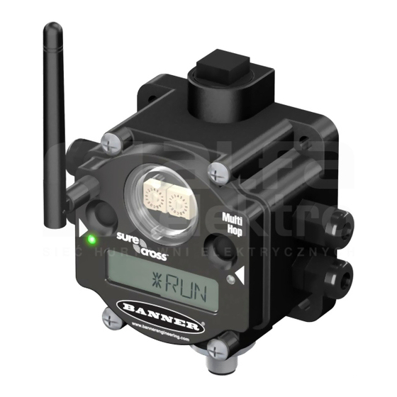
® Sure Cross Performance DX80 Wireless I/O Networks The GatewayPro has no serviceable parts inside the housing and no wiring chamber. During setup or standard operation, there should not be a need to open the GatewayPro. 2.3 DX80 GatewayPro The GatewayPro has many of the same features as the Gateway and Node, including the LEDs, the buttons, LCD, and Euro-style connector. -
Page 10: Wiring Diagrams
® Sure Cross Performance DX80 Wireless I/O Networks 2.5 Wiring Diagrams Use the following drawings to correctly wire power and I/O to the SureCross Wireless radio devices. For more information about wiring sensors to the SureCross devices, refer to Sensor Connections. 2.5.1 5-pin M12/Euro-style Wiring for Gateways and DX85s Wiring the 5-pin Euro-style connector depends on the model and power requirements of the device. -
Page 11: Dimensions
® Sure Cross Performance DX80 Wireless I/O Networks Wire Color Description White/orange + Tx White/blue Orange –Tx Blue –Rx 2.6 Dimensions The DX80, DX83, and DX70 models all share the same housing and mounting hole dimensions. 2.6.1 Gateways and Nodes 65.0 22.2 [2.56”]... -
Page 12: Gatewaypro
® Sure Cross Performance DX80 Wireless I/O Networks DX80...E Housings 148.1 mm [5.83”] 36.2 mm [1.42”] 2X Dia 8.3 mm [0.33”] 13.7 mm [0.54”] 55.9 mm [2.20”] 6 mm [0.24”] 2X 12-14 NPSM 3.2 mm [0.13”] 75.3 mm [2.96”] 20.1 mm [0.79”] 87.6 mm [3.45”]... -
Page 13: Dx80...E Housings
® Sure Cross Performance DX80 Wireless I/O Networks 2.6.4 DX80...E Housings 148.1 mm [5.83”] 36.2 mm [1.42”] 2X Dia 8.3 mm [0.33”] 13.7 mm [0.54”] 55.9 mm [2.20”] 6 mm [0.24”] 2X 12-14 NPSM 3.2 mm [0.13”] 75.3 mm [2.96”] 20.1 mm [0.79”] 87.6 mm... -
Page 14: Setting Up Your Wireless Network
® Sure Cross Performance DX80 Wireless I/O Networks 3 Setting Up Your Wireless Network To set up and install your wireless network, follow these steps. Disconnect the power from your Sure Cross devices. 1. Configure the DIP switches of all devices. For DIP switch configurations, refer to the product's datasheet. 2. -
Page 15: Applying Power To The Gateway Or Node
Performance and non-Performance radios within the same network, refer the technical note titled Mixing Performance Radios and 150 mW Radios in the Same Network listed on the Wireless Support - FAQs section of Banner's Wireless website. -
Page 16: Led Behavior For The Gateways
® Sure Cross Performance DX80 Wireless I/O Networks 2. Enter binding mode on the Node. • If you have a two-button Node, triple-click button 2. • If you have a one-button Node, triple-click the button. • If you have a Node with no buttons, remove the top cover and set both the left and right rotary dials to F to enter binding mode. -
Page 17: Conducting A Site Survey (Gateway And Nodes)
® Sure Cross Performance DX80 Wireless I/O Networks LED 1 LED 2 Node Status Flashing red Flashing red Device Error Flashing red, 1 per 3 sec No Radio Link 3.7 Conducting a Site Survey (Gateway and Nodes) A Site Survey, also known as a Radio Signal Strength Indication (RSSI), analyzes the radio communications link between the Gateway and any Node within the network by analyzing the radio signal strength of received data packets and reporting the number of missed packets that required a retry. -
Page 18: Interpreting The Site Survey Results
® Sure Cross Performance DX80 Wireless I/O Networks SITE (Site Survey) Menu The SITE menu displays the results of a Site Survey conducted with this Gateway. Gateway The SITE menu displays the device number of the Node the Site Survey was conducted with as well as the missed, green, yellow, and red received packet SITE count. -
Page 19: Site Survey Troubleshooting
Higher gain antennas focus the energy of the radio signal in a specific direction and extend the signal’s range. Using data radios is another option to consider when trying to extend the range of a radio network. For more information on data radios, please refer to Banner’s white paper on range extension on www.bannerengineering.com/wireless. - Page 20 ® Sure Cross Performance DX80 Wireless I/O Networks The Gateway also displays the Site Survey results on the LCD (for models with an LCD). For one transmit and receive interval, the Gateway saves the lowest signal strength. The LCD and Modbus registers contain the results of the last 100 samples.
-
Page 21: Installing Your Sure Cross ® Radios
Remove Moisture and Condensation. If condensation is present in any device, add a small desiccant packet to the inside of the radio. To help vent the radios, Banner also sells a vented plug (model number BWA-HW-031) for the 1/2-inch NPT port of the SureCross radios. -
Page 22: Other Installation Requirements
To achieve the best radio performance, carefully consider the installation locations for the Gateways and Nodes and select locations without obstructions in the path. For more information about antennas, please refer to the Antenna Basics reference guide, Banner document p/n 132113. 4.3.2 Increase the Height of the Antennas Position the external antenna vertically for optimal RF communication. -
Page 23: Collocated Radios
® Sure Cross Performance DX80 Wireless I/O Networks 4.3.3 Collocated Radios When the radio network’s master device is located too close to another radio device, communications between all devices is interrupted. For this reason, always assign a unique Network ID to your wireless networks. The Network ID (NID) is a unique identifier you assign to each wireless network to minimizes the chances of two collocated networks interfering with each other. -
Page 24: Weatherproof Remote Antenna Installations
I/O Isolation. When connecting analog and discrete I/O to external equipment such as VFDs (Variable Frequency Drives), it may be appropriate to install interposing relays and/or loop isolation devices to protect the DX80 unit from transients, noise, and ground plane interference originating from devices or the environment. Contact Banner Engineering Corp. for more information. -
Page 25: Mount A Dome Antenna To The Enclosure
® Sure Cross Performance DX80 Wireless I/O Networks 4.4.3 Mount a Dome Antenna to the Enclosure Use a -D dome antenna when mounting an antenna directly to the outside of the enclosure. 1. Dome antenna 2. DIN rail and DIN rail bracket 3. -
Page 26: Use An N-Type, Pole-Mounted Antenna
® Sure Cross Performance DX80 Wireless I/O Networks 4.4.4 Use an N-Type, Pole-Mounted Antenna This antenna mounts remotely from the box, with the SureCross device mounted inside the box. Ground the surge suppressor and antenna. Keep the ground wire as short as possible and make all ground connections to a single-point ground system to ensure no ground loops are created. - Page 27 ® Sure Cross Performance DX80 Wireless I/O Networks Models Description List Price BWC-4MNFN30 LMR400 N-Type Male to N-Type Female, 30 m $296 Model Description Connection List Price Surge Suppressor, Bulkhead, RP-SMA BWC-LMRSFRPB RP-SMA to RP-SMA $111 Type Surge Suppressor, bulkhead, N-Type, N-Type Female, N-Type BWC-LFNBMN-DC $120...
-
Page 28: Advanced Setup Instructions And Additional Information
Performance DX80 Wireless I/O Networks 5 Advanced Setup Instructions and Additional Information Refer to the following sections for advanced setup instructions or additional information on Banner's SureCross wireless technology and its uses. 5.1 DX80 Menu Structure The Gateways and Nodes each have their own menu structure and options. - Page 29 ® Sure Cross Performance DX80 Wireless I/O Networks 5.1 DX80 Node Set-up Menu When power is applied, the DX80 begins running. The display screen auto loops through the RUN menu and communication begins between the Gateway and Node(s). Auto looping through the RUN menu is the normal operating mode for all devices on the wireless network.
-
Page 30: Run Menu
® Sure Cross Performance DX80 Wireless I/O Networks 5.1.1 RUN Menu The RUN menu displays the network ID (NID), device name (Gateway or Node), and the I/O values of the device. Gateway Node On the Gateway, the I/O displayed may be the I/O of the Gateway or of a selected Node. -
Page 31: Dinfo (Device Information) Menu
® Sure Cross Performance DX80 Wireless I/O Networks 5.1.2 DINFO (Device Information) Menu The DINFO menu displays some device-specific information. Gateway Node On the Gateway, the DINFO menu displays the device name, the network ID (NID), slave ID, baud rate, and parity. When in extended DINFO address mode, the DINFO menu also displays the maximum Node DINFO... -
Page 32: Fctry (Factory) Menu
The FCTRY menu displays the version numbers of various components within the device, including the radio micro number, the LCD number, the device’s serial number, the device’s model number, and the production date. Gateway Node If you call Banner Engineering for technical support, having this information available may help diagnose your particular FCTRY FCTRY problem. -
Page 33: Site (Site Survey) Menu
® Sure Cross Performance DX80 Wireless I/O Networks 5.1.4 SITE (Site Survey) Menu The SITE menu displays the results of a Site Survey conducted with this Gateway. Gateway The SITE menu displays the device number of the Node the Site Survey was conducted with as well as the missed, green, yellow, and red received packet SITE count. -
Page 34: Dvcfg (Device Configuration) Menu
® Sure Cross Performance DX80 Wireless I/O Networks 5.1.5 DVCFG (Device Configuration) Menu On Gateways, the DVCFG menu allows users to set various device-specific parameters, including the network ID (NID), slave ID (SLID), baud rate, and parity. In extended address mode, use this menu to also set the maximum number of radio devices (MAXN) within the network and the extended address binding code (XADR). -
Page 35: Derr (Device Error) Menu
® Sure Cross Performance DX80 Wireless I/O Networks Node DVCFG Device Config. Single-click Button 2 Single-click Button 1 to advance through menu (NID) (NADR) (XADR) Network ID Node Address Extended Addressing Single-click Single-click Single-click Button 2 Button 2 Button 2 Single-click AUTO Button 2... -
Page 36: Web-Based Configuration
® Sure Cross Performance DX80 Wireless I/O Networks On the Gateway use the DERR menu to clear, disable, or ignore error messages generated by devices within the network. The Node number that generated the error and the error code (EC) display onscreen. Single-click button 1 to advance through the menu of CLEAR (clear this particular instance of the error from the system), DISABL (disable this particular error from appearing from this specific Node), and IGNORE (ignore this error but do not remove it from the system). -
Page 37: Accessing The Web-Based Configuration Screens
PC with an IP address different from the Ethernet Bridge or GatewayPro IP addresses. (Refer to Banner document p/n 133116 for detailed instructions on setting up the host computer’s network IP address.) For example, change the PC host IP address to: 192.168.0.2. To access the configuration screens, follow these steps. -
Page 38: Changing The Ip Address
® Sure Cross Performance DX80 Wireless I/O Networks 1. Open a Web browser and log into the Ethernet Bridge or GatewayPro by typing the IP address in the browser location window: http://192.168.0.1. The Web home page for the Ethernet Bridge or GatewayPro displays. 2. -
Page 39: Binding Mode: What Does It Do
® Sure Cross Performance DX80 Wireless I/O Networks 5.3 Binding Mode: What does it do? Binding Nodes to a Gateway ensures the Nodes only exchange data with the Gateway they are bound to. After a Gateway enters binding mode, the Gateway automatically generates and transmits a unique extended addressing (XADR), or binding, code to all Nodes within range that are also in binding mode. -
Page 40: Manually Choosing An Extended Address (Binding) Code - Node
® Sure Cross Performance DX80 Wireless I/O Networks 12. Single click button 2 when code entry is complete. The Gateway LCD displays the entered value for confirmation by showing CONFRM XADR, then repeating back your value. 13. Single click button 2 to save the code and exit the XADR menu. When entering the extended address code, the digits auto fill with whatever position the rotary switch is currently in. -
Page 41: Automatic Binding Using The Menu Navigation
® Sure Cross Performance DX80 Wireless I/O Networks 4. Using both rotary dials on the Gateway, select a Network ID. The left rotary dial acts as the left digit and the right rotary dial acts as the right digit of the Network ID. In extended addressing mode, the Network ID can only be set from the rotary dials while in the (NID) menu. -
Page 42: Setting The Maximum System Devices
® Sure Cross Performance DX80 Wireless I/O Networks For devices with batteries integrated into the housing, remove the battery for one minute to cycle power to the device. After making any changes to DIP switch settings, you must cycle power to the device or the DIP switch changes will not be recognized. -
Page 43: Setting The Baud Rate
® Sure Cross Performance DX80 Wireless I/O Networks 8. If using a Network ID (NID), adjust both rotary switches back to the NID value. To avoid losing the network connection between the Gateway and Nodes, reset the rotary switches back to their appropriate values before leaving the *DVCFG sub-menus. -
Page 44: Gateway Link Failure
® Sure Cross Performance DX80 Wireless I/O Networks Host System Node 1 Gateway Node 2 5.8.2 Gateway Link Failure Gateway link failures are determined by three global parameters: polling interval, maximum missed message count, and re-link count. The polling interval (or rate) defines how often the Gateway communicates with each Node to verify the radio link is operating. -
Page 45: Node Link Failure
Gateway’s register I/O 15 clear error conditions. Clearing a lost radio link error does not restore communications. Banner recommends determining and resolving the cause of the radio link error, then allowing the system to auto-recover the lost communications. -
Page 46: Output Units
4 to 20 mA. LCD: 4.00mA–20.00mA 5.9.3 Interpreting Register Values in the Banner Wireless System The units conversion table defines the type and range of values for each type of I/O. The wireless devices have many different units of measure for inputs including: milliamp (mA), voltage (V), temperature (°C or °F), humidity (RH), or a raw 16-bit or 32-bit value. - Page 47 ® Sure Cross Performance DX80 Wireless I/O Networks The following table defines the range of values and descriptions for input units. Holding Register I/O Range Representation Input Type Data Conversion Description Min. Max. Min. Max. Discrete (20 mA ÷ 65535) × Reg Value = Linear mapping of unsigned 0 to 20 mA 0.0 mA...
-
Page 48: Setting Up The Wireless Network Using The Rotary Dials
5.10 Setting up the Wireless Network Using the Rotary Dials Follow these steps to set up your wireless network using the rotary dials instead of using extended addressing mode. Banner recommends using Extended Addressing Mode, but some older products may only recognize Rotary Dial Address Mode. -
Page 49: Setting The Network Id Using The Rotary Dials
® Sure Cross Performance DX80 Wireless I/O Networks For factory configured kits, the Network ID and Device Addresses have been assigned. Otherwise, use the rotary dials (shown below) to define both the NID and Device Address for each device. To operate more than 15 Nodes in your wireless network, use Extended Address Mode and device binding instead of Rotary Dial Address Mode. - Page 50 ® Sure Cross Performance DX80 Wireless I/O Networks To ignore the Channel Search Mode results and use a Network ID that Channel Search Mode determined was in use, double-click button two. The word IGNORE displays on the LCD and both LEDs are solid red. The Gateway enters RUN mode, operating on the Network ID chosen despite being in use by another device.
-
Page 51: System Layouts
® Sure Cross Performance DX80 Wireless I/O Networks 6 System Layouts Because of the flexibility of the DX80 wireless devices, many different configurations using Gateways, Nodes, GatewayPros, Ethernet Bridges, Modbus slave devices, data radios, data radio repeaters, and/or solar powered systems are possible, both as stand-alone systems and host-connected systems. -
Page 52: Gateway With Multiple Nodes (Dx80)
DX80G... DX80 or DX80 Performance Gateway DX80N... DX80 or DX80 Performance Node 81398 User Configuration Tool (free to download from the Wireless Products section of Banner Engineering's website) BWA-HW-006 RS-485 to USB adapter cable (not shown) www.bannerengineering.com - Tel: 763.544.3164... -
Page 53: Gateway Configured As A Modbus Master
DX85 Modbus RTU Remote I/O DX80N... DX80 or DX80 Performance Nodes or FlexPower Nodes 81398 User Configuration Tool (free to download from the Wireless Products section of Banner Engineering's website) BWA-HW-006 RS-485 to USB adapter cable (not shown) www.bannerengineering.com - Tel: 763.544.3164... -
Page 54: Modbus Rtu
® Sure Cross Performance DX80 Wireless I/O Networks 6.2 Modbus RTU 6.2.1 Modbus RTU Host Controlled Operation A simple host-connected system uses an RS-485 serial cable to connect the Gateway to a host system. The host system may be a PC or a PLC unit. Because the serial cable is used to connect to a host system, the communications protocol used is Modbus RTU. -
Page 55: Modbus Rtu With Multiple Slave Devices
® Sure Cross Performance DX80 Wireless I/O Networks 6.2.2 Modbus RTU with Multiple Slave Devices In the example host controlled configuration, the Gateway is a Modbus slave to the host system, but remains the master of the wireless network. The Gateway is connected directly to the host system using an RS-485 serial cable. This system may also connect DX85 Modbus RTU Remote I/O devices to the serial cable to expand the available I/O. -
Page 56: Modbus Rtu With Multiple Slave Devices - Layout 2
® Sure Cross Performance DX80 Wireless I/O Networks 6.2.3 Modbus RTU with Multiple Slave Devices - Layout 2 In this example host controlled configuration, the Gateway is a Modbus slave to the host system, but remains the master of the wireless network. The Gateway is connected directly to the host system using a fieldbus connection. -
Page 57: Modbus/Tcp And Ethernet/Ip
® Sure Cross Performance DX80 Wireless I/O Networks 6.3 Modbus/TCP and EtherNet/IP 6.3.1 Host Connected - DX80 GatewayPro Connect a GatewayPro to a host system using the GatewayPro's industrial Ethernet connection. To connect the GatewayPro directly to the host system, use a crossover cable. By default, the GatewayPro is a ™... -
Page 58: Data Radios
® Sure Cross Performance DX80 Wireless I/O Networks 6.4 Data Radios 6.4.1 Data Radios Data radios extend the range of the Modbus network and keep the network addressing system simple. In this basic example, the data radios act as a wire replacement to extend the Modbus network. 1. -
Page 59: Data Radios With A Gateway As The Modbus Master
® Sure Cross Performance DX80 Wireless I/O Networks 6.4.3 Data Radios with a Gateway as the Modbus Master In this example network, the Gateway is both the master for the radio network and the master for the Modbus network. The DX85 shown is a Modbus slave; the data radios extend the range of the Modbus network. Item Model No. -
Page 60: Sensor Connections
Analog Sensors. For analog sensors, the ground/dc common of the sensor should be connected to the ground of the DX80 device. For best results, Banner recommends that the power source for the sensor and DX80 device is the same. 7.1 Discrete Inputs Discrete Sensors. -
Page 61: Discrete Inputs, Mini-Beam
Analog Sensors. For analog sensors, the ground/dc common of the sensor should be connected to the ground of the DX80 device. For best results, Banner recommends that the power source for the sensor and DX80 device is the same. 7.3.1 Analog Inputs, Powered using SureCross Device Terminals... -
Page 62: Analog Inputs, Powered From Switch Power
® Sure Cross Performance DX80 Wireless I/O Networks 7.3.2 Analog Inputs, Powered from Switch Power Two-Wire Sensors Three-Wire Sensors sensor − Analog IN − Analog IN − − sensor dc common dc common Two-wire analog sensor or two-wire NAMUR proximity Three-wire analog sensor using a FlexPower Node and sensor using a FlexPower Node and powered using the powered using the Node’s switch power. -
Page 63: Analog Inputs, Qt50U Long-Range Ultrasonic Sensor
® Sure Cross Performance DX80 Wireless I/O Networks 7.3.5 Analog Inputs, QT50U Long-Range Ultrasonic Sensor QT50U Ultrasonic Sensor Four-wire QT50U sensor, using a FlexPower Node, and powered using the Node’s switch power terminal. The (wh) QT50U output is set to 4–20 mA. QT50U Do not apply power to the Ax+ connection. -
Page 64: Surecross Power Solutions
8.2 What is FlexPower Banner’s FlexPower technology supplies a true wireless solution by allowing the device to operate using either 10 to 30 V dc, 3.6 V lithium D cell batteries, or solar power. This unique power management system can operate a FlexPower Node and an optimized sensing device for up to five years on a single lithium D cell. -
Page 65: Flexpower With Integrated Battery
® 8.2.3 FlexPower Solar Supply Banner’s FlexPower Solar Supply Assembly can supply power to two radio devices, including a FlexPower Node, a FlexPower Gateway, or a data radio. When used with a FlexPower Node and sensors, the FlexPower Solar Assembly supplies enough power to run most sensors at higher sample and report rates than a single battery can reasonably support. -
Page 66: Discrete Configuration
For each sensor characterized, a boost voltage and warmup time was specified. The sample and reports rates were varied to calculate the estimated battery life. For example, a Banner QT50ULBQ6-75390 sensor set to a boost voltage of 15 volts, a warm-up time of 500 milliseconds, and a sample and report rate of 15 minutes, should have a battery life of 4.45 years. -
Page 67: Temperature And Humidity Sensor
For each sensor characterized, a boost voltage and warmup time was specified. The sample and reports rates were varied to calculate the estimated battery life. For example, a Banner Optical sensor, model SM312DQD-78419, set to a boost voltage of 5 volts, a warm-up time of 4 milliseconds, and a sample and report rate of 16 seconds, should have a battery life of just over 6 years. -
Page 68: Calculating Battery Life
8.3.4 Calculating Battery Life To estimate the battery life for a sensor not included in our list, use the configuration and cable shown (Banner cable BWA- HW-010) to measure the current draw of your system. -
Page 69: Example Solar Powered Systems
® Sure Cross Performance DX80 Wireless I/O Networks 1. Averaging Fluke Meter 2. DX81 Battery Supply Module 3. DX80 FlexPower Node with MINI- BEAM 4. BWA-HW-010 Cable, FlexPower Current Monitoring 8.4 Example Solar Powered Systems For installations without wired power, use the solar powered assembly to power data radios, FlexPower Gateways, or FlexPower Nodes connected to sensors that require more power than a single battery unit can supply. -
Page 70: Parallel Solar Systems
® Sure Cross Performance DX80 Wireless I/O Networks This example system shows a solar power system powering data radios and Gateways, expanding the wireless network far beyond Host System the limits of wired power sources. NID A NID A NID 1 NID A NID 1 NID 1... -
Page 71: Battery Backup Feature
® Sure Cross Performance DX80 Wireless I/O Networks 1. BWA-SOLAR-001. FlexPower Solar Supply, includes panel, solar controller, rechargeable batteries, and mounting materials. 2. DX80N... DX80 or DX80 Performance FlexPower Node or 10 to 30 V dc Node. 3. Power Splitter Cable, quick disconnect, 5-pin Euro, female trunk, male branches. - Page 72 ® Sure Cross Performance DX80 Wireless I/O Networks Host System Item Model No. Description BWA-SOLAR-001 FlexPower Solar Supply, includes panel, solar controller, rechargeable batteries, and mounting materials DX80N... DX80 or DX80 Performance FlexPower Node or 10 to 30 V dc Node DX80G*M2S-P Performance FlexPower Gateway, No I/O DX80DR*M-H...
-
Page 73: Maintenance
® Sure Cross Performance DX80 Wireless I/O Networks 9 Maintenance Follow these instructions to perform basic maintenance tasks. 9.1 Replacing the Main Body Gasket Check the main body gasket every time a SureCross device is opened. Replace the gasket when it is damaged, discolored, or showing signs of wear. The gasket must be: •... -
Page 74: Replacing The Integrated Battery (Dx80 Models)
Potential electrostatic charging hazard — only clean with a damp cloth. • The replacement battery MUST be a Banner approved battery, model number BWA-BATT-001. Use of a different battery will VOID the intrinsic safety rating of this device and may result in an explosion! •... - Page 75 Do not replace battery when an explosive dust atmosphere may be present. • The replacement battery MUST be a Banner approved battery, model number BWA-BATT-001. Use of a different battery will VOID the intrinsic safety rating of this device and may result in an explosion! •...
-
Page 76: Troubleshooting
® Sure Cross Performance DX80 Wireless I/O Networks 10 Troubleshooting The following troubleshooting tips include some basic instructions for common problems. 10.1 Startup Problems The following problems are associated with starting up your radios. ® The radio won't wake up. While in storage mode, the radio does not operate. All Sure Cross radios powered from an integrated battery ship from the factory in storage mode to conserve the battery. - Page 77 ® Sure Cross Performance DX80 Wireless I/O Networks LED 1 LED 2 Definition/Solution Gateway, DX85: Modbus communication error For a Gateway system, a Modbus communications error indicates a bad transmission or checksum error between the host and the Gateway device. For a Flashing red GatewayPro system, a Modbus communications error indicates a communications problem internal to the GatewayPro.
-
Page 78: Lcd Message Codes
® Sure Cross Performance DX80 Wireless I/O Networks 10.3 LCD Message Codes These message codes display on the device's LCD. Message Solution BAD EE System Error. A system error typically represents a failure of the EE PROM. Contact the factory for replacement. EC XX The XX refers to the Modbus register 8 message code shown in Modbus Message Codes for Register 8... -
Page 79: Inputs And Outputs
When a specific Node/Gateway radio link fails, all pertinent wired outputs are de-energized until the link is recovered (see component datasheet for more information.) Through this process, users of Banner wireless networks can be assured that disruptions in the communications link result in predictable system behavior. - Page 80 ® Sure Cross Performance DX80 Wireless I/O Networks OUT 1 = Normal OUT 2 = Normal OUT 1 = Normal Node 1 OUT 2 = Normal OUT 3 = Normal OUT 4 = Normal Gateway OUT 1 = Normal OUT 2 = Normal Node 2 Figure 6.
-
Page 81: Accessories
® Sure Cross Performance DX80 Wireless I/O Networks 11 Accessories The accessories list includes FCC approved antennas, antenna cabling, surge suppressors, power supplies, replacement batteries, enclosures, cables, and other hardware. 11.1 Selecting an Enclosure Select the enclosure size based on what you intend to mount inside it. Always select the largest enclosure you can to allow for future expansion. - Page 82 ® Sure Cross Performance DX80 Wireless I/O Networks With Clear Covers Models Description List Price BWA-AH14126C Enclosure, Polycarbonate, with Clear Cover, 14 × 12 × 6 $204 BWA-AH16148C Enclosure, Polycarbonate, with Clear Cover, 16 × 14 × 8 $250 BWA-AH181610C Enclosure, Polycarbonate, with Clear Cover, 18 ×...
-
Page 83: Selecting An Antenna
® Sure Cross Performance DX80 Wireless I/O Networks DIN Rail Kits (Machine Screws and Slot Nuts) Models Description List Price BWA-AH18DRK DIN Rail Kit, 18", Includes 2 Slot Nuts, 2 Machine Screws, and DIN Rail Accessories Models Description List Price BWA-AHSNK Slot Nut Kit, Includes 2 Nuts and 2 Screws BWA-AHSPM... -
Page 84: Antennas: Dome
® Sure Cross Performance DX80 Wireless I/O Networks Omni-Directional Antennas with RP-SMA Male Connections Models Frequency Description List Price BWA-9O2-RA 900 MHz 2 dBi, Rubber fixed right angle Models Frequency Description List Price BWA-2O1-001 2.4 GHz 1 dBi, Rubber, 1 inch tall 11.2.2 Antennas: Dome Omni-Directional Dome Antennas Models... -
Page 85: Antennas: Yagi N-Type
® Sure Cross Performance DX80 Wireless I/O Networks 11.2.5 Antennas: Yagi N-Type Directional (Yagi) Antennas with an N-Type Female Connection Models Frequency Description List Price BWA-9Y6-A 6.5 dBd, 6.8 × 13 inches Outdoor $135 900 MHz BWA-9Y10-A 10 dBd, 6.8 × 24 inches Outdoor $150 11.2.6 Antenna Cables: RP-SMA to RP-SMA Use these cables to connect a radio to a bulkhead surge suppressor or a bulkhead surge suppressor to an RP-SMA... -
Page 86: Antenna Cables: N-Type
® Sure Cross Performance DX80 Wireless I/O Networks 11.2.8 Antenna Cables: N-Type These LMR400 cables are antenna extension cables, connecting an N-type antenna to another N-type antenna cable. These cables are usually used outside the enclosure. Models Description List Price BWC-4MNFN3 LMR400 N-Type Male to N-Type Female, 3 m BWC-4MNFN6... -
Page 87: Flexpower Supplies And Replacement Batteries
® Sure Cross Performance DX80 Wireless I/O Networks Models Description List Price DC Power Supply, 0.63 Amps, 24 V dc, with DIN Rail Mount, Class I Division 2 PSDINP-24-06 (Groups A, B, C, D) Rated DC Power Supply, 1.3 Amps, 24 V dc, with DIN Rail Mount, Class I Division 2 PSDINP-24-13 $127 (Groups A, B, C, D) Rated... -
Page 88: Relays
® Sure Cross Performance DX80 Wireless I/O Networks 11.4 Relays Models Description List Price Interface Relay Box, 18 to 26 V dc inputs, isolated relay outputs (not IB6RP $233 shown) BWA-RELAY-12V Relay, Blade Style with Base, 12 V BWA-RELAY-24V Relay, Blade Style with Base, 24 V BWA-RH1B-UDC12V Relay, Blade Style, No Base, 12 V (replacement part) BWA-RH1B-UDC24V... - Page 89 Performance DX80 Wireless I/O Networks Brackets List Price BWA-HW-034 • DIN rail clip, black plastic This standard Banner bracket can also be used to remotely mount dome antennas. SMBAMS18RA • Right-angle SMBAMS series bracket with 18 mm hole • Articulation slots for 90+° rotation •...
-
Page 90: Other Accessories
® Sure Cross Performance DX80 Wireless I/O Networks Brackets List Price 4X Ø6 BWA-BK-006 • Mounts both the K50U Ultrasonic sensor and a Wireless Q45U Node Ø33.5 4X Ø5.2 11.6 Other Accessories 11.6.1 Other Accessories The following are other accessories available for the SureCross product line or available as stand-alone devices. 11.6.1 GPS Modules Models Description... -
Page 91: Sensors
® Sure Cross Performance DX80 Wireless I/O Networks Models Description List Price DX85M8P4 DX85 Modbus RTU Remote I/O, 8 Discrete IN, 4 Discrete OUT $475 DX85M0P0M4M4 DX85 Modbus RTU Remote I/O, 4 Analog IN, 4 Analog OUT (0 to 20 mA) $475 DX85M-P7 DX85 Modbus RTU Remote I/O, Up to 12 sinking inputs or up to 12 NMOS sinking... -
Page 92: Lights
® Sure Cross Performance DX80 Wireless I/O Networks Sensors with a Serial Interface The following sensors are designed to be used with any of the 1-Wire Serial Interface Nodes. Models Description Datasheet List Price Temperature and Humidity Sensor, ±2% Accuracy, 1-wire serial interface M12FTH4Q $175... -
Page 93: Cables
® Sure Cross Performance DX80 Wireless I/O Networks Wireless Lights Models Description Datasheet EZ-LIGHT ® K70 Wireless Touch Button; can be ordered with up to K70DXN9T2**** three colors; 900 MHz 189843 ® EZ-LIGHT K70 Wireless Touch Button; can be ordered with up to K70DXN2T2**** three colors;... - Page 94 ® Sure Cross Performance DX80 Wireless I/O Networks Adapter Cables Models Description List Price Adapter cable, USB to RS-485, for use with the User BWA-HW-006 $132 Configuration Tool software (UCT) Adapter cable with power, USB to RS-485, for use with BWA-UCT-900 the User Configuration Tool software (UCT), supplies $132...
- Page 95 ® Sure Cross Performance DX80 Wireless I/O Networks Models Description List Price Splitter cable, wall wart for external power split to 5-pin M12/ BWA-HW-026 Euro-style male and 5-pin M12/Euro-style female (to power a M-H at 1 Watt while configuring it through the MHCT) Other Splitter Cables Models Description...
-
Page 96: Hardware And Replacement Parts
® Sure Cross Performance DX80 Wireless I/O Networks Euro-Style Cordsets - Double Ended When using the FlexPower Node with integrated battery, use a double ended cordset. When using a FlexPower Node with external power supply, use a single ended cordset. If using the communication lines, the cable length cannot exceed 3 meters (10 ft). -
Page 97: Cable Glands And Plugs
® Sure Cross Performance DX80 Wireless I/O Networks 11.6.7 Cable Glands and Plugs Models Description List Price BWA-HP.5-10 Dummy Hole Plugs, 1/2-inch NPT, 10 pieces BWA-HW-031 Vent Plug, 1/2" NPT, IP67 Cable Glands, 1/2-inch NPT, 10 pieces, Cordgrips for cable BWA-CG.5-10 diameters 0.17’’... -
Page 98: Radio Certifications
Sure Cross Performance DX80 Wireless I/O Networks 12 Radio Certifications Banner's SureCross product line is certified by the FCC, European Union, and many other countries for operation within specific radio frequencies. 12.1 FCC Certification, 900MHz The DX80 Module complies with Part 15 of the FCC rules and regulations. -
Page 99: Fcc Certification, 900 Mhz, 1 Watt Radios
® Sure Cross Performance DX80 Wireless I/O Networks 12.2 FCC Certification, 900 MHz, 1 Watt Radios The DX80 Module complies with Part 15 of the FCC rules and regulations. FCC ID: UE3RM1809 This device complies with Part 15 of the FCC Rules. Operation is subject to the following two conditions: (1) this device may not cause harmful interference, and (2) this device must accept any interference received, including interference that may cause undesired operation. -
Page 100: Certified For Use In The Following Countries
® Sure Cross Performance DX80 Wireless I/O Networks FCC ID: UE300DX80-2400 This device complies with Part 15 of the FCC Rules. Operation is subject to the following two conditions: (1) this device may not cause harmful interference, and (2) this device must accept any interference received, including interference that may cause undesired operation. - Page 101 ® Sure Cross Performance DX80 Wireless I/O Networks Radio Modules Country 900 MHz (150 mW) 900 MHz (1 Watt) 2.4 GHz (65 mW) Belgium Brazil Bulgaria Canada Chile China, People's Republic of Colombia Cyprus Czech Republic Denmark Ecuador El Salvador Estonia Egypt Finland...
-
Page 102: Exporting Sure Cross ® Radios
Radio Certifications section of the product manual. The Sure Cross wireless products were certified for use in these countries using the antenna that ships with the product. When using other antennas, verify you are not exceeding the transmit power levels allowed by local governing agencies. Consult with Banner Engineering Corp. -
Page 103: Warnings
Radio Certifications section of the product manual. The Sure Cross wireless products were certified for use in these countries using the antenna that ships with the product. When using other antennas, verify you are not exceeding the transmit power levels allowed by local governing agencies. Consult with Banner Engineering Corp. - Page 104 Performance DX80 Wireless I/O Networks Mexico Address: Phone: +52 81 8363 2714 or 01 800 BANNERE (toll free) Banner Engineering de Mexico Monterrey Head Office Website: www.bannerengineering.com.mx Edificio VAO Av. David Alfaro Siqueiros No.103 Col. Valle Oriente C.P.66269 Email: mexico@bannerengineering.com...
- Page 105 Index main body 73 radio time-out 78, 79 ground 22 RF device time-out 78 antenna ground wire 23–26 remote installation 26 antenna installation remote 23–26 seasonal changes 23 I/O isolation 23–26 setting baud rate 43 input value 46–48 setting parity 43 integrated battery 65 setting slave ID 42 bad EE 78...
Need help?
Do you have a question about the Sure Cross Performance GatewayPro DX80P*A6 series and is the answer not in the manual?
Questions and answers