Banner DX80 Installation & Operation Manual
Hide thumbs
Also See for DX80:
- Network manual (110 pages) ,
- Product manual (109 pages) ,
- Reference manual (96 pages)
Table of Contents
Advertisement
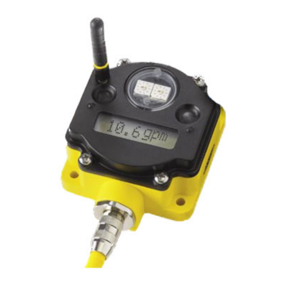
DX80 Gateway Installation & Operation Manual
The gateway and endpoint nodes communicate over multiple wireless channels within the 902-928MHz
ISM Spectrum. Different configurations of internal & external antennas and different RF power options
allow you to customize the wireless range from a few feet to > 10000'. The implementation of FHSS
methodology allows for reliable communications even in harsh industrial environments. The gateway
station and endpoint nodes communicate with acknowledge handshaking to verify reception of data. Error
checking is also performed to validate the data transmission.
The Gateway and Endpoint node communications always collect signal strength information. The
collected data can help gauge the strength and performance of the wireless signals. The received signal
strength can be adjusted by various parameters such as the TX power settings and Receiver Sensitivity
Modes. Hardware configurations can also impact the signal strength, such as internal / external antenna and
antenna placement.
Banner Engineering Corp • Minneapolis, MN USA
Sensonix Incorporated • Plymouth, MN USA
Preliminary Information
RF by
Features
•
Operates in 902-928MHz ISM
Spectrum
• FHSS operation
• RF configurations – up to 150 mw
• External antenna connection
• RS232 / RS485
• 2 Analog In (4-20ma)
• 2 Analog Out (4-20ma)
• 2 Digital In
• 2 Digital Out
• 10-30v DC
• LCD, Control buttons, LED
indicators
• Stand alone operation
• DX80 - NEMA 6, IP67 enclosure
www.bannerengineering.com
1 of 18
• Tel: 763.544.3164
• 763.519.7042
www.sensonix.com
Advertisement
Table of Contents

Related Manuals for Banner DX80


Summary of Contents for Banner DX80
- Page 1 • LCD, Control buttons, LED indicators • Stand alone operation • DX80 - NEMA 6, IP67 enclosure The gateway and endpoint nodes communicate over multiple wireless channels within the 902-928MHz ISM Spectrum. Different configurations of internal & external antennas and different RF power options allow you to customize the wireless range from a few feet to >...
- Page 2 Preliminary Information 1 Mechanical Low Profile DX80 enclosure, a two connector model is shown. A DX80 gateway unit in a single connector model is also available All DX80 mechanical enclosures Model # Description Euro Connectors High Profile Profile LPGW1 Line Powered Gateway...
- Page 3 Junction box models – euro connectors, glands, Euro-style connector or glands? Mounting holes Wiring diagram PC Board with Terminals to identify connection. Banner Engineering Corp • Minneapolis, MN USA • Tel: 763.544.3164 www.bannerengineering.com Sensonix Incorporated • Plymouth, MN USA 3 of 18 •...
-
Page 4: External Antenna
Only Banner approved external antenna should be connected to DX80 devices. Unsuitable antenna may void the user’s authority to operate the equipment. The approved antennas are listed in the accessory section. 2.3 Mounting hardware requirements DX80 devices have four #10 screw holes used for mounting the device vertically or horizontally. - Page 5 2.5 Euro-Style Connectors The Gateway devices have 8-pin or 12-pin euro-style connectors. The pin numbering and wire color is identified below. The signal wire to pin number association table identifies all wires for the DX80 Gateway. 2.5.1 8-pin Euro-Style Wiring (models LPGW2, BPDEN1) Signal to pin association for 8-pin Euro-Style connectors.
- Page 6 Preliminary Information 2.5.2 12-pin Euro-Style Wiring Signal to pin association for 12-pin Euro-Style connectors. DX80 Gateway models Euro-Style Connector LPGW1 – Line Powered Gateway Cable Internal Wire Pin # Euro QD1 female Euro QD2 male Wire Color Color White White...
- Page 7 19.2k baud, one start bit, two stop bits, no flow control and a slave address of ‘01’. The following Modbus function codes are supported. For DX80 configuration commands and DX80 user commands refer to the DX80 Interface Protocol document.
-
Page 8: Setup And Operation
Preliminary Information 3 Setup & Operation 3.1 DX80 Front Panel The DX80 front panel picture helps identify each switch, button and LED. The rotary switches in the middle of the round window are identified as a 10’s switch (left switch) and a 1’s switch (right switch). -
Page 9: Setup & Configuration
*Some endpoint nodes may require up to 20 seconds after power-on to synchronize with the gateway. 3.4 LabView Configuration Node configuration, Sensor configuration, System Parameters – dynamic TDMA Banner Engineering Corp • Minneapolis, MN USA • Tel: 763.544.3164 www.bannerengineering.com Sensonix Incorporated • Plymouth, MN USA 9 of 18 •... -
Page 10: Front Panel Operation
3.5 Front Panel Operation The front panel rotary switches and push button switches control the display information and configuration of the DX80 devices. The flow diagram below shows the button sequences and operational flow for what is possible with the DX80 Gateway. - Page 11 RF processor, software version for the communications processor and the production date. To exit the factory settings state, double click button 2. Banner Engineering Corp • Minneapolis, MN USA • Tel: 763.544.3164 www.bannerengineering.com Sensonix Incorporated • Plymouth, MN USA 11 of 18 •...
- Page 12 When testing the communication signal link using site survey, make sure to keep all wireless units separated by at least 3 feet. Banner Engineering Corp • Minneapolis, MN USA • Tel: 763.544.3164 www.bannerengineering.com Sensonix Incorporated • Plymouth, MN USA 12 of 18 •...
- Page 13 If you change the network ID on one device, gateway or node, all devices intended for that wireless network need to be changed to the same network ID. Double click button 2 to put the device back into Run Mode. Banner Engineering Corp • Minneapolis, MN USA • Tel: 763.544.3164 www.bannerengineering.com Sensonix Incorporated •...
- Page 14 Preliminary Information Configuration: Modbus Slave Number. The DX80 gateway can have a Modbus slave address from 1 to 99. Each member of a Modbus RTU serial network must have a unique slave number. From within the configuration menu, single click button 1 until the LCD display reads ‘MODSLV’ and then single click button 2.
-
Page 15: Maintenance
Preliminary Information 4 Maintenance The DX80 family of products is designed to be IP67 compliant and maintenance free. Annual cleaning and inspection is always recommended. When inspecting the equipment watch for housing cracks, residue build-up or corrosion on connectors. It is also a good idea to verify the mechanical connections are tight and still in good condition. -
Page 16: Ethernet Interface
(2) Push Button Switches Electronics 40C to +85C 6 Character LCD -30C to +70C LCD reduced visibility 40C to +85C Banner Engineering Corp • Minneapolis, MN USA • Tel: 763.544.3164 www.bannerengineering.com Sensonix Incorporated • Plymouth, MN USA 16 of 18 • 763.519.7042 www.sensonix.com... -
Page 17: Agency Certifications
1/2 wave Swivel Nearson S467AH-915S 2.0 dBi Fixed / Mobile 20 cm antenna Cables Mounting Brackets Banner Engineering Corp • Minneapolis, MN USA • Tel: 763.544.3164 www.bannerengineering.com Sensonix Incorporated • Plymouth, MN USA 17 of 18 • 763.519.7042 www.sensonix.com... - Page 18 S FLT – Sensor response is outside of normal operating parameters. P FLT – Parameter error in processing sensor status. Gateway ModBus errors Banner Engineering Corp • Minneapolis, MN USA • Tel: 763.544.3164 www.bannerengineering.com Sensonix Incorporated • Plymouth, MN USA 18 of 18 •...
Need help?
Do you have a question about the DX80 and is the answer not in the manual?
Questions and answers