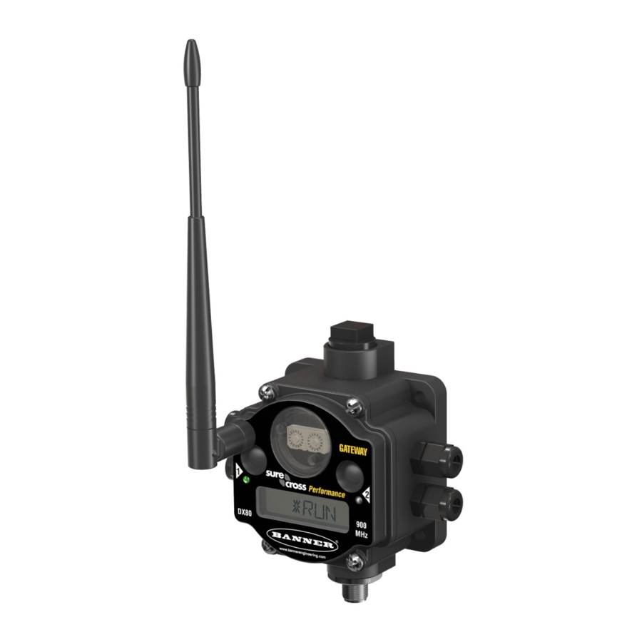
Banner Sure Cross DX80 Instruction Manual
Network basics
Hide thumbs
Also See for Sure Cross DX80:
- Instruction manual (105 pages) ,
- Quick start manual (10 pages) ,
- Instruction manual (69 pages)
Table of Contents
Advertisement
Quick Links
Download this manual
See also:
Instruction Manual
Advertisement
Table of Contents

Subscribe to Our Youtube Channel
Summary of Contents for Banner Sure Cross DX80
- Page 1 ® Sure Cross DX80 Network Basics Instruction Manual Original Instructions 136689 Rev. A 1 October 2018 © Banner Engineering Corp. All rights reserved 136689...
-
Page 2: Table Of Contents
1.3 Ring Networks ................................... 3 1.4 Tree Networks ................................... 4 1.5 Mesh Networks ................................. 4 1.6 Star Networks ..................................4 ® 2 Banner's Sure Cross Network ..........................5 2.1 Network ID ..................................6 2.2 Device ID .................................... 6 2.3 Basic Wireless Network ..............................6 3 Modbus 485 ................................ -
Page 3: Networks
Many of Banner’s newest products are part of a network, both wired and wireless. As such, understanding networking basics is important when using or providing technical support to Banner’s products. -
Page 4: Tree Networks
® Sure Cross DX80 Network Basics 1.4 Tree Networks In a tree network, the lowest level contains the nodes, referred to as leaves, whose only function is to transmit information to the next highest level, the repeaters. The repeaters forward the data to the gateway. Pros—New nodes added to the system do not slow down the entire network. -
Page 5: Banner's Sure Cross ® Network
The Master/Slave Relationship In the Sure Cross DX80 wireless network, the Gateway is the master device and initiates all communications with the slave devices, the DX80 Nodes. The slave devices can not initiate communications with... -
Page 6: Network Id
Because the radio network operates over the air, there are limited ways to electrically separate collocated networks. To keep collocated networks separated, Banner uses a network ID number, sometimes abbreviated as NID. Each wireless network operating within radio range is assigned a unique network ID number. -
Page 7: Modbus 485
® Sure Cross DX80 Network Basics 3 Modbus 485 Modbus Remote Terminal Unit (RTU) running over RS-485 cabling is sometimes abbreviated as Modbus 485 and is a master-slave communications protocol typically used for industrial applications. RS-485 refers to the physical layer of the network. - Page 8 DX80 Network Basics When a new Node is powered up and added to the wireless network, the Modbus registers are activated at a unique location saved for each wireless network Node device. Refer to Banner’s Host Controller System Instruction Manual (p/n 132114 ) for more information about the Modbus register map.
-
Page 9: Modbus/Tcp And Ethernet/Ip ™ Networks
® Sure Cross DX80 Network Basics ™ 4 Modbus/TCP and EtherNet/IP Networks Attaching host devices to the Modbus network using standard Ethernet hardware requires using one of several Ethernet- based communications protocols. Modbus/TCP is an open standard protocol developed by the Modbus IDA (www.modbus.org). It is very similar to Modbus RTU except that it uses standard Internet communication protocols, just like Web communications or e-mail. -
Page 10: Gatewaypro
The Web page interface accessed using the Ethernet Bridge provides a mechanism for setting parameters on the wireless network. Although most wireless parameters are initially configured at Banner, some of the parameters not configured include using the Gateway hardware as a Modbus RTU master, setting up I/O maps for the Modbus master actions, backup and restoring network configurations, changing the IP address of the Gateway, and enabling the EtherNet/IP protocol. -
Page 11: The Osi Seven Layer Model
® Sure Cross DX80 Network Basics 5 The OSI Seven Layer Model The Open Systems Interconnection (OSI) seven layer model attempts to describe network communication protocols as a layered series of steps necessary to transmit information between dissimilar devices or networks. The lowest level of the model is the physical level and pertains to the actual transfer media (air, wires), connector types, voltages, and signaling speeds for a specific type of network. -
Page 12: Osi And Wireless Networks
® Sure Cross DX80 Network Basics 5.1 OSI and Wireless Networks Although the SureCross wireless product is a proprietary wireless network and the various protocol layers are proprietary, the wireless network can be compared to the standard seven layer model. Instead of wires creating a connection, the 900 MHz or 2.4 GHz radio signal transmits the binary data, creating a radio signal “link.”... -
Page 13: Network Basics Glossary
Internet communication protocols. Node Nodes are remote I/O slave devices within Banner's wireless sensor networks. Sensors and other devices connect to the Node's inputs or outputs, allowing the Node to collect sensor data and wirelessly transmit it to the Gateway. Every Sure Cross device is a transceiver, meaning it can transmit and receive data.


Need help?
Do you have a question about the Sure Cross DX80 and is the answer not in the manual?
Questions and answers