Advertisement
Quick Links
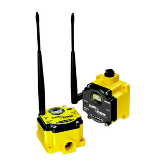
SureCross DX70 Wireless Point-to-Point Kits
The SureCross™ DX70 wireless kits include build a point-to-point network using two devices and configured I/O
Features
Models
When ordering the SureCross DX70 device, order the kits listed below. The kits include the Gateway, Node, mounting hardware, access
hardware, antennas, and cables. Each kit's devices ship from the factory bound and with the inputs and outputs mapped as shown in the
I/O mapping tables.
Kit Models
DX70K9M6EM1
DX70K2M6EM1
DX70K9M6ED1
DX70K2M6ED1
Internal antenna models are also available, but are not UL Listed. For more information, contact your local Banner Engineering Corp.
representative.
WARNING: Not To Be Used for Personnel Protection
Never use this product as a sensing device for personnel protection. Doing so could lead to serious injury
or death. This product does NOT include the self-checking redundant circuitry necessary to allow its use in
personnel safety applications. A sensor failure or malfunction can cause either an energized or de-ener-
gized sensor output condition.
P/N 133214 rev. H
The SureCross™ DX70 wireless series consists of a radio frequency network built around
two devices and configured I/O.
• Wireless industrial I/O system with discrete (sourcing or sinking) inputs and outputs,
analog inputs and outputs, and a link loss output that may be selected or deselected
to be one of the four outputs
• DIP switches for user configuration
• 10 to 30V dc power input
• Site Survey analyzes the network's signal strength and reliability
• Frequency Hopping Spread Spectrum (FHSS) technology and Time Division Multiple
Access (TDMA) control architecture combine to ensure reliable data delivery within
the unlicensed Industrial, Scientific, and Medical (ISM) band
• Transceivers provide bidirectional communication between the Gateway and Node, in-
cluding fully acknowledged data transmission
• Lost RF links are detected and relevant outputs set to user-defined conditions
• External or internal antenna
For additional information, the most recent version of all documentation, and a complete
list of accessories, refer to Banner Engineering's website,
surecross.
Frequency
Inputs and Outputs
900 MHz
Inputs: Four selectable discrete, two 0-20 mA analog
Outputs: Four sourcing discrete, two 0-20 mA analog
2.4 GHz
900 MHz
Inputs: Eight selectable discrete on the Node, four selectable discrete on the
Gateway
2.4 GHz
Outputs: Four sourcing discrete on the Node, eight sourcing discrete on the
Gateway
6/16/2011
www.bannerengineering.com/
0 133214
8
Advertisement

Related Manuals for Banner SureCross DX70 Series


Summary of Contents for Banner SureCross DX70 Series
- Page 1 Outputs: Four sourcing discrete on the Node, eight sourcing discrete on the Gateway Internal antenna models are also available, but are not UL Listed. For more information, contact your local Banner Engineering Corp. representative. WARNING: Not To Be Used for Personnel Protection Never use this product as a sensing device for personnel protection.
- Page 2 SureCross DX70 Wireless Point-to-Point Kits Replacement DX70 Devices Kit Models Device Frequency Replacement DX70 Device Node DX70N9X6S4P4M2M2 DX70K9M6EM1 900 MHz ISM Band Gateway DX70G9X6S4P4M2M2 Node DX70N2X6S4P4M2M2 DX70K2M6EM1 2.4 GHz ISM Band Gateway DX70G2X6S4P4M2M2 DX70K9M6ED1 Node DX70N9X6S8P4 900 MHz ISM Band Gateway DX70G9X6S4P8 DX70K2M6ED1...
- Page 3 SureCross DX70 Wireless Point-to-Point Kits DX70 Dimensions The DX70 Gateway and Node use the same housing, which is also the same in size and mounting holes as the DX80 housing. 65.0 [2.56”] [0.31”] 65.0 80.3 [4.17”] [2.56”] [3.16”] 7.65 [0.30”] 1/2”...
- Page 4 Between 26% and 50% missed packets Every 1 second More than 50% missed packets I/O Mapping and Sensor Connections All DX70 pairs ship from Banner Engineering with the I/O mapped. DX70...EM1 Kits www.bannerengineering.com - tel: 763-544-3164 P/N 133214 rev. H...
- Page 5 SureCross DX70 Wireless Point-to-Point Kits Terminal Label DX70 Gateway DX70 Node Terminal Label Discrete IN 1* Discrete OUT 1 or Lost Link* Discrete IN 2 Discrete OUT 2 Discrete IN 3 Discrete OUT 3 Discrete IN 4 Discrete OUT 4 Analog IN 1 Analog OUT 1 Analog IN 2...
- Page 6 SureCross DX70 Wireless Point-to-Point Kits Terminal Label DX70 Gateway DX70 Node Terminal Label Discrete OUT 5 from Discrete IN 5 Discrete OUT 6 from Discrete IN 6 Discrete OUT 7 from Discrete IN 7 Discrete OUT 8 from Discrete IN 8 Wiring Diagrams Discrete Input Wiring (PNP) Discrete Input Wiring (NPN)
- Page 7 Moisture and Condensation. If condensation is present in any device, add a small desic- cant packet to the inside of the radio. To help vent the radios, Banner also sells a vented plug (model number BWA-HW-031) for the 1/2" NPT port of the SureCross radios.
- Page 8 SureCross DX70 Wireless Point-to-Point Kits Replacing the Rotary Dial Access Cover Check the rotary dial access cover o-ring every time the access cover is removed. Replace the o-ring when it is damaged, discolored, or showing signs of wear. The o-ring should be: •...
- Page 9 Gateways and Nodes and select locations without obstruc- tions in the path. For more information about antennas, please refer to the Antenna Basics reference guide, Banner document p/n 132113. Increase the Height of the Antennas Position the external antenna vertically for optimal RF communication.
- Page 10 For more detailed information about how antennas work and how to install them, refer to Antenna Basics, Banner document 132113 (also included as a chapter within the product manual).
- Page 11 SureCross DX70 Wireless Point-to-Point Kits Antenna Installation Always install and properly ground a qualified surge suppressor when installing a remote antenna system. Remote antenna configura- tions installed without surge suppressors invalidate the manufacturer's warranty. Always keep the ground wire as short as possible and make all ground connections to a single-point ground system to ensure no ground loops are created.
- Page 12 SureCross DX70 Wireless Point-to-Point Kits Model Number Description BWC-1MRSFRSB4 RG58 Cable, RP-SMA TO RP-SMA Female, Bulkhead, 4 m DIN-35-105 DIN Rail section, 105 mm long, 35 mm design SMBDX80DIN DIN Rail Bracket Assembly for DX70 and DX80 models. Mounting an RP-SMA Antenna Remotely This antenna mounts remotely from the box, with the SureCross device mounted inside the box.
- Page 13 SureCross DX70 Wireless Point-to-Point Kits Model Number Description BWC-1MRSFRSB1 RG58 Cable, RP-SMA TO RP-SMA Female Bulkhead, 1 m BWC-1MRSFRSB2 RG58 Cable, RP-SMA TO RP-SMA Female Bulkhead, 2 m BWC-1MRSFRSB4 RG58 Cable, RP-SMA TO RP-SMA Female, Bulkhead, 4 m DIN-35-105 DIN Rail section, 105 mm long, 35 mm design SMBDX80DIN Bracket Assembly, DIN Rail, for DX80 BWA-EF14128...
- Page 14 SureCross DX70 Wireless Point-to-Point Kits Model Number Description BWA-9O5-B Antenna, Omni, 900 MHz, 5 dBd/7.2 dBi, With ground plane, N Female BWA-2O8-A Antenna, Omni, 2.4 GHz, 8.5 dBi, N Female, Fiberglass 24” BWA-2O6-A Antenna, Omni, 2.4 GHz, 6 dBi, N Female, Fiberglass 16” BWC-4MNFN3 LMR400 Cable, N-Male to N-Female, 3 Meters BWC-4MNFN6...
- Page 15 SureCross DX70 Wireless Point-to-Point Kits Valid Network IDs are 01 through 32, in decimal, established using both rotary dials. The left dial may be set to 0, 1, 2, or 3. The right dial may be set from 0 to 9 when the left dial is at 0, 1, or 2; or set to 0 through 2 when the left dial is at 3. (Positions A through F are invalid network ID numbers.)** 7.
- Page 16 SureCross DX70 Wireless Point-to-Point Kits Switches Device Settings Link Timeout - 1 second * Default positions. Input 1 is not available when the lost link output is selected. ** The lost link option is only available on the 4P4M2M2 models Accessing the DIP Switches To access the DIP switches, follow these steps: 1.
- Page 17 RF link fails, all pertinent wired outputs are brought to a predefined state until the link is recovered (default DIP switch setting). Through this process, users of Banner wireless networks can be assured that disruptions in the communications link result in predictable system behavior.
- Page 18 SureCross DX70 Wireless Point-to-Point Kits 1. The RF link between the devices has timed out. In this example, the lost link is energized and the outputs have been programmed by the DIP switches to go to their de-energized states (default DIP switch position). 2.
- Page 19 SureCross DX70 Wireless Point-to-Point Kits Antennas Not to scale Part No. Model No. Description Omni-Directional Antennas 76908 BWA-9O2-C 902-928 MHz, 2 dBi, RP-SMA Male (ships with 900 MHz DX80 devices) 77816 BWA-2O2-C 2.4 GHz, 2 dBi, RP-SMA Male, Rubber swivel, 3 1/4” (ships with 2.4 GHz DX80 devices) 77817 BWA-2O5-C...
- Page 20 SureCross DX70 Wireless Point-to-Point Kits Part No. Model No. Description 77422 PS24W DC Power Supply, 500 mA, 24V dc, Demo kit power supply 74321 EZAC-E-QE5 DC Power Supply, 700 mA, 24V dc, 5-pin Euro-style QD, Hard- wired AC power connection 73466 EZAC-E-QE5-QS5 DC Power Supply, 700 mA, 24V dc, 5-pin Euro-style QD, 5-pin...
- Page 21 SureCross DX70 Wireless Point-to-Point Kits Part No. Model No. Description 77820 BWC-1MRSMN2 LMR200 RP-SMA to N Male, 2M 78544 BWC-1MRSFRSB0.2 RG58, RP-SMA to RP-SMAF Bulkhead, 0.2M 78337 BWC-1MRSFRSB1 RG58, RP-SMA to RP-SMAF Bulkhead, 1M 78338 BWC-1MRSFRSB2 RG58, RP-SMA to RP-SMAF Bulkhead, 2M 77488 BWC-1MRSFRSB4 RG58, RP-SMA to RP-SMAF Bulkhead, 4M...
- Page 22 SureCross DX70 Wireless Point-to-Point Kits Part No. Model No. Description 10200 BWA-HW-010 Cable, FlexPower Current Monitoring Enclosures and Relay Boxes Part No. Model No. Description 11320 BWA-EF14128 Enclosure Fiberglass Hinged 14"x12"x8" 11321 BWA-EF1086 Enclosure Fiberglass Hinged 10"x8"x6" 11322 BWA-EF866 Enclosure Fiberglass Hinged 8"x6"x6" 11326 BWA-PA1412 Panel, 14 x 12...
- Page 23 SMBDX80DIN Bracket assembly, DIN rail, flat mount Radio Certifications Banner's SureCross product line is certified by the FCC, European Union, and many other countries for operation within specific radio frequencies. FCC Certification, 900MHz The DX80 Module complies with Part 15 of the FCC rules and regulations.
- Page 24 SureCross DX70 Wireless Point-to-Point Kits Model Number Antenna Type Maximum Gain BWA-9O5-B Omni Base Whip ≤7.2 dBi BWA-9Y10-A Yagi ≤10 dBi Table 1. Type certified antennas FCC Certification, 2.4GHz The DX80 Module complies with Part 15 of the FCC rules and regulations. FCC ID: UE300DX80-2400 This device complies with Part 15 of the FCC Rules.
- Page 25 SureCross DX70 Wireless Point-to-Point Kits Certified For Use in the Following Countries The SureCross radio devices are approved for use in the following countries. Model Families Country Frequency DX80 DX80 1 DX70 DX70 1 DX91 DX99 DX80D Watt Watt Australia 2.4 GHz Austria 2.4 GHz...
- Page 26 SureCross DX70 Wireless Point-to-Point Kits Model Families Country Frequency DX80 DX80 1 DX70 DX70 1 DX91 DX99 DX80D Watt Watt Malta 2.4 GHz Mexico 900 MHz Mexico 2.4 GHz Netherlands 2.4 GHz New Zealand 2.4 GHz Norway 2.4 GHz Panama 900 MHz Panama 2.4 GHz...
- Page 27 Additional Statements - 900 MHz This device has been designed to operate with the antennas listed on Banner Engineering’s website and having a maximum gain of 9 dBm. Antennas not included in this list or having a gain greater that 9 dBm are strictly prohibited for use with this device. The required antenna impedance is 50 ohms.
- Page 28 All specifications published in this document are subject to change. Banner reserves the right to modify the specifications of prod- ucts without notice. Banner Engineering reserves the right to update or change documentation at any time. For the most recent version of any documentation, refer to our website: www.bannerengineering.com.
- Page 29 Banner Engineering Corp. warrants its products to be free from defects in material and workmanship for one year following the date of shipment. Banner Engineering Corp. will repair or replace, free of charge, any product of its manufacture which, at the time it is returned to the factory, is found to have been defective during the warranty period.
Need help?
Do you have a question about the SureCross DX70 Series and is the answer not in the manual?
Questions and answers