Banner Sure Cross DX80 Quick Start Manual
Gateway for wireless q45 sensors
Hide thumbs
Also See for Sure Cross DX80:
- Instruction manual (105 pages) ,
- Quick start manual (6 pages) ,
- Instruction manual (13 pages)
Advertisement
Sure Cross
DX80 Gateway for Wireless Q45
®
Sensors
Datasheet
Configurable DX80 Gateway that uses DIP switches to map inputs from up to six Nodes (or Wireless Q45 Sensors) to the
Gateway's outputs
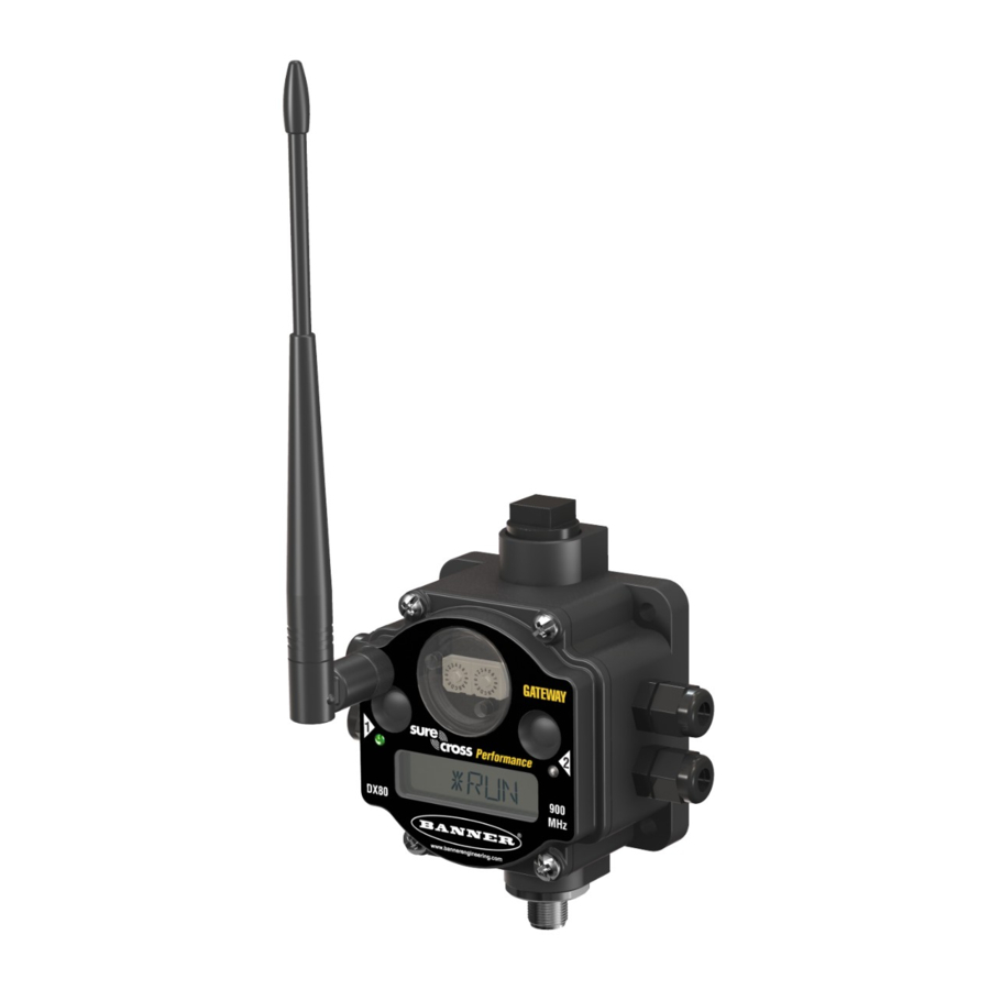
DX80 Model
DX80...C Model
For additional information, updated documentation, and a list of accessories, refer to Banner Engineering's website,
www.bannerengineering.com.
WARNING:
•
Do not use this device for personnel protection
•
Using this device for personnel protection could result in serious injury or death.
•
This device does not include the self-checking redundant circuitry necessary to allow its use in
personnel safety applications. A device failure or malfunction can cause either an energized (on) or de-
energized (off) output condition.
Models
Model
Frequency
DX80G2M6-Q
2.4 GHz ISM Band
DX80G2M6-QC
Configure and Install Your Q45 Network
Follow these steps to set up and install your Wireless Q45 network.
1. On the Wireless Q45 Sensor Node:
a) Configure the DIP switches (if applicable).
b) Apply power.
2. On the Gateway or DXM:
a) Configure the DIP switches (if applicable).
b) Wire the I/O.
c) Apply power.
3. Bind the Q45 to the master radio.
4. Observe the LED behavior to verify the devices are communicating to each other.
5. Using the configuration software, configure the I/O mapping between the Q45 and its master radio.
6. Conduct a Site Survey between the Gateway and the Wireless Q45.
7. Install your devices.
Configure the Gateway
Original Document
161862 Rev. E
®
The Sure Cross
wireless system is a radio frequency network with integrated I/O that operates
in most environments and eliminates the need for wiring runs. Systems are built around a
Gateway, which acts as the wireless network master device, and one or more Wireless Q45
Sensors.
•
Wireless industrial I/O device with six discrete (sourcing) inputs and six discrete
(sourcing) outputs
•
DIP switches allow the user to select one of eight defined I/O mapping configurations to
automatically map the Nodes' inputs to this Gateway's outputs
•
Frequency Hopping Spread Spectrum (FHSS) technology ensures reliable data delivery
within the unlicensed Industrial, Scientific, and Medical (ISM) band
•
Transceivers provide bidirectional communication between the Gateway and Node,
including fully acknowledged data transmission
•
Site Survey analyzes the network's signal strength and reliability and displays the results
on the Gateway's LCD
•
LCD shows I/O status, Site Survey results, and network status information
•
Lost RF links are detected and relevant outputs set to user-defined conditions
Environmental Rating
IP67, NEMA 6
IP20, NEMA 1
3 December 2020
I/O
Inputs: Six sourcing discrete
Outputs: Six sourcing discrete
161862
Advertisement
Table of Contents

Related Manuals for Banner Sure Cross DX80


Summary of Contents for Banner Sure Cross DX80
- Page 1 LCD shows I/O status, Site Survey results, and network status information DX80...C Model • Lost RF links are detected and relevant outputs set to user-defined conditions For additional information, updated documentation, and a list of accessories, refer to Banner Engineering's website, www.bannerengineering.com. WARNING: •...
-
Page 2: Configure The Dip Switches
® Sure Cross DX80 Gateway for Wireless Q45 Sensors Configure the DIP Switches Before changing DIP switch positions, disconnect the power. Any changes made to the DIP switches are not recognized until after power is cycled to the device. For parameters not set using the DIP switches, use the User Configuration Software to make configuration changes. For parameters set using the DIP switches, the DIP switch positions override any changes made using the User Configuration Software. - Page 3 * Default configuration. To use up to 47 Nodes or Wireless Q45 Sensors with this Gateway, you must use a Modbus host controller Host Configuration manual, Banner document part system. For more information about using a host controller system, refer to the number 132114.
- Page 4 ® Sure Cross DX80 Gateway for Wireless Q45 Sensors One Node to One Gateway DIP Switches 6 = ON 7 = OFF 8 = OFF One SureCross DX80 Node with 6 inputs and 6 outputs: Node 1, IN 1 → Gateway OUT 1; Gateway IN 1 → Node 1, OUT 1 Node 1, IN 2 →...
- Page 5 ® Sure Cross DX80 Gateway for Wireless Q45 Sensors Wire the Gateway's I/O Wire the Gateway’s I/O Tx/+ Rx/- x . Discrete IN x RX/-. Serial communication line for the Gateway. No connection for Nodes x . Discrete OUT x TX/+.
- Page 6 ® Sure Cross DX80 Gateway for Wireless Q45 Sensors Discrete Bit-Packed Registers Discrete bit-packed registers include the discrete status registers, discrete inputs, and discrete outputs. Bit packing involves using a single register, or range of contiguous registers, to represent I/O values. When networks use similar Nodes to gather data using the same I/O registers for each Node, discrete data from multiple Nodes can be bit packed into a single register on the Gateway.
- Page 7 ® Sure Cross DX80 Gateway for Wireless Q45 Sensors 5-pin M12/Euro-style Wiring for Gateways and DX85s Wiring the 5-pin M12/Euro-style connector depends on the model and power requirements of the device. Connecting power to the communication pins will cause permanent damage. 5-pin M12/Euro-style Connector (male) Wire Color Description...
-
Page 8: Interpreting The Site Survey Results
® Sure Cross DX80 Gateway for Wireless Q45 Sensors Conducting a Site Survey (Gateway and Nodes) A Site Survey, also known as a Radio Signal Strength Indication (RSSI), analyzes the radio communications link between the Gateway and any Node within the network by analyzing the radio signal strength of received data packets and reporting the number of missed packets that required a retry. -
Page 9: Environmental Specifications
Using higher gain antennas to focus the energy of the radio signal in a specific direction and extend the signal’s range • Adding data radios to the network to extend the range of a radio network. For more information on data radios, please refer to Banner’s white paper on range extension on www.bannerengineering.com/wireless. Specifications Performance 2.4 GHz Radio Specifications Radio Range 2.4 GHz Compliance... - Page 10 When using other antennas, verify you are not exceeding the transmit power levels allowed by local governing agencies. This device has been designed to operate with the antennas listed on Banner Engineering’s website and having a maximum gain of 9 dBm. Antennas not included in this list or having a gain greater that 9 dBm are strictly prohibited for use with this device.
Need help?
Do you have a question about the Sure Cross DX80 and is the answer not in the manual?
Questions and answers