Table of Contents
Advertisement
Quick Links
User Guide
DVS-21
Content
1 Glossary..................................................................................................................................................... 6
2 Program environment ................................................................................................................................ 7
2.1 User rights and application instances ................................................................................................. 7
2.2 Registered file types ........................................................................................................................... 7
2.3 Menus ................................................................................................................................................. 7
2.4 Toolbar ............................................................................................................................................... 9
3 Settings .................................................................................................................................................... 10
3.1 ICS Settings ...................................................................................................................................... 10
Sprache/Language ............................................................................................................................. 10
Default ................................................................................................................................................ 10
Color ................................................................................................................................................... 10
Templates ........................................................................................................................................... 10
3.2 RS232 settings ................................................................................................................................. 11
4 Online functions ....................................................................................................................................... 11
4.1 Monitor .............................................................................................................................................. 12
Filter function ...................................................................................................................................... 13
4.2 Data transfer ..................................................................................................................................... 13
Userbank List ...................................................................................................................................... 14
Connection via modem ....................................................................................................................... 14
4.3 Firmware (DVS update) .................................................................................................................... 15
4.4 System time ...................................................................................................................................... 16
4.5 Simulation ......................................................................................................................................... 16
5 Tools ........................................................................................................................................................ 17
5.1 Database editor ................................................................................................................................ 17
5.2 Offline monitor .................................................................................................................................. 17
5.3 Compare files ................................................................................................................................... 18
5.4 Speech storage ................................................................................................................................ 19
5.5 Documentation ................................................................................................................................. 21
5.6 Plausibility ......................................................................................................................................... 22
5.7 Dependencies ................................................................................................................................... 23
6 System programming .............................................................................................................................. 24
6.1 System data ...................................................................................................................................... 24
General data ....................................................................................................................................... 24
System clock....................................................................................................................................... 25
02/2018 • V.1.0 • L. Wolle
© 2017 ProCom
®
Professional Communication & Service GmbH • Technical changes reserved.
1/131
Advertisement
Table of Contents

Summary of Contents for Procom DVS-21
-
Page 1: Table Of Contents
5.7 Dependencies ........................... 23 6 System programming ..........................24 6.1 System data ............................24 General data ............................24 System clock............................25 02/2018 • V.1.0 • L. Wolle 1/131 ® Professional Communication & Service GmbH • Technical changes reserved. © 2017 ProCom... - Page 2 Operation mode DB-Radio ......................... 45 fixed audio channels: .......................... 45 7.10 4IOS..............................46 Operation mode Default ........................46 Operation mode Safe receiving ......................48 02/2018 • V.1.0 • L. Wolle 2/131 ® Professional Communication & Service GmbH • Technical changes reserved. © 2017 ProCom...
- Page 3 7.18 4DSS .............................. 68 7.19 4DAE .............................. 69 8 Call stations and devices ......................... 70 8.1 Overview ............................70 8.2 ProCom Call stations ........................70 General data ............................71 Keys ..............................71 8.3 Third party-Call stations (Analog) ..................... 72 General data ............................72 Keys ..............................
- Page 4 10.5 Level control (loud/quiet) ......................100 10.6 Level control (attenuation) (manual/automatic) ................100 Operation mode Control (Control by means of Flag or Line) ............100 02/2018 • V.1.0 • L. Wolle 4/131 ® Professional Communication & Service GmbH • Technical changes reserved. © 2017 ProCom...
- Page 5 WPS 08 + AWC 06 (8, 14, 20, 26, 32, 38) ..................130 PMS/PMK 16 (16, 32, 48, 64, 80, 96) ....................130 DTA-LAN (24, 78, 132, 186, 240) ..................... 131 02/2018 • V.1.0 • L. Wolle 5/131 ® Professional Communication & Service GmbH • Technical changes reserved. © 2017 ProCom...
-
Page 6: Glossary
The following rules apply to every program: Flag OR activates the program Flag NAND suppresses the execution Flag (OUT) is activated if the program is activ 02/2018 • V.1.0 • L. Wolle 6/131 ® Professional Communication & Service GmbH • Technical changes reserved. © 2017 ProCom... -
Page 7: Program Environment
\export\. The program creates 3 files. Import Import description lists for lines, flags and modules. (CSV format) Quit Closes the program. 02/2018 • V.1.0 • L. Wolle 7/131 ® Professional Communication & Service GmbH • Technical changes reserved. © 2017 ProCom... - Page 8 Pin assignment of the modules. (Displayed with the default image viewer) Examples Programming examples for typical use. Info Version and release information of the program. 02/2018 • V.1.0 • L. Wolle 8/131 ® Professional Communication & Service GmbH • Technical changes reserved. © 2017 ProCom...
-
Page 9: Toolbar
Manages the call stations of the system. Module rack Manages the hardware equipment of the system. Programs Manages the programming of the system. 02/2018 • V.1.0 • L. Wolle 9/131 ® Professional Communication & Service GmbH • Technical changes reserved. © 2017 ProCom... -
Page 10: Settings
Night operation is already entered when an amplifier is created! Template Fault indication The specified Flag is entered as Fault report flag and in the Flag Description. 02/2018 • V.1.0 • L. Wolle 10/131 ® Professional Communication & Service GmbH • Technical changes reserved. © 2017 ProCom... -
Page 11: Rs232 Settings
CPU of the system. Under certain circumstances these can result in delays, as the CPU must first activate the respective mode. 02/2018 • V.1.0 • L. Wolle 11/131 ® Professional Communication & Service GmbH • Technical changes reserved. © 2017 ProCom... -
Page 12: Monitor
The data of a recording are additionally stored in a temporary file (ICS\temp\montemp.icsm). 02/2018 • V.1.0 • L. Wolle 12/131 ® Professional Communication & Service GmbH • Technical changes reserved. © 2017 ProCom... -
Page 13: Filter Function
The filter setting is transferred to the CPU and is evaluated actively by it! 4.2 Data transfer This module is used to read and write a system program. 02/2018 • V.1.0 • L. Wolle 13/131 ® Professional Communication & Service GmbH • Technical changes reserved. © 2017 ProCom... -
Page 14: Userbank List
Once a connection to the system via the modem has been established successfully, all the described functions are also available. 02/2018 • V.1.0 • L. Wolle 14/131 ® Professional Communication & Service GmbH • Technical changes reserved. © 2017 ProCom... -
Page 15: Firmware (Dvs Update)
The system has two code banks. This offers the option of transferring new firmware to the inactive code bank while the system is running. 02/2018 • V.1.0 • L. Wolle 15/131 ® Professional Communication & Service GmbH • Technical changes reserved. © 2017 ProCom... -
Page 16: System Time
Reads the current system time of the CPU. 4.5 Simulation This module is used to simulate telegrams on the system bus. In addition, modules can be tested. 02/2018 • V.1.0 • L. Wolle 16/131 ® Professional Communication & Service GmbH • Technical changes reserved. © 2017 ProCom... -
Page 17: Tools
The *.icsm file extension is registered for the .exe program monitor in the operating system. Files with records can thus be opened directly by means of the file system. 02/2018 • V.1.0 • L. Wolle 17/131 ® Professional Communication & Service GmbH • Technical changes reserved. © 2017 ProCom... -
Page 18: Compare Files
Marked datasets in the middle lists are transferred to the lower elements for direct comparison for direct comparison. Differences in bytes are identified in red here. 02/2018 • V.1.0 • L. Wolle 18/131 ® Professional Communication & Service GmbH • Technical changes reserved. © 2017 ProCom... -
Page 19: Speech Storage
User Guide DVS-21 5.4 Speech storage Recording, playback and testing of the DSS1 (Speech storage) module 02/2018 • V.1.0 • L. Wolle 19/131 ® Professional Communication & Service GmbH • Technical changes reserved. © 2017 ProCom... - Page 20 Starts the selected function locally on the PC and online on the module Timer Display of the active time of an active activity Playback duration Duration of playback from RAM or Flash 02/2018 • V.1.0 • L. Wolle 20/131 ® Professional Communication & Service GmbH • Technical changes reserved. © 2017 ProCom...
-
Page 21: Documentation
The Print Section button prints only the visible section while the Print System programming button prints complete documentation without Module rack allocation. 02/2018 • V.1.0 • L. Wolle 21/131 ® Professional Communication & Service GmbH • Technical changes reserved. © 2017 ProCom... -
Page 22: Plausibility
This message appears if a Flag is only used in one Flag has no function program and thus has no function. 02/2018 • V.1.0 • L. Wolle 22/131 ® Professional Communication & Service GmbH • Technical changes reserved. © 2017 ProCom... -
Page 23: Dependencies
DVS version of the system. A warning appears in the event of a possible version conflict. 02/2018 • V.1.0 • L. Wolle 23/131 ® Professional Communication & Service GmbH • Technical changes reserved. © 2017 ProCom... -
Page 24: System Programming
The input fields are partially preconfigured automatically and should be checked and System identification adjusted. In the case of new systems, the system date is entered automatically. 02/2018 • V.1.0 • L. Wolle 24/131 ® Professional Communication & Service GmbH • Technical changes reserved. © 2017 ProCom... -
Page 25: System Clock
West European summertime Activates the internal correction of the system clock according to the official determination of Summer- /Winter-time change-overs. 02/2018 • V.1.0 • L. Wolle 25/131 ® Professional Communication & Service GmbH • Technical changes reserved. © 2017 ProCom... -
Page 26: Default Volume - Intercom
User Guide DVS-21 DCF-77 The DVS-21 system clock can be synchronized with a DCF-77 receiver. The following soft- and hardware versions are required: CPU1 (05.09.2007) manual change required Hardware DCF-77 Receiver ProCom DCF-77 Radio clock module CPU1 Firmware as from Version 7.27... -
Page 27: Modem
Should a fixed level be used, then the min. specification is used as a basis. Modem 02/2018 • V.1.0 • L. Wolle 27/131 ® Professional Communication & Service GmbH • Technical changes reserved. © 2017 ProCom... -
Page 28: Call Stations And Devices
The always show all option lists all stations in the left-hand overview, or only the stations of the type marked in the right-hand selection. 02/2018 • V.1.0 • L. Wolle 28/131 ® Professional Communication & Service GmbH • Technical changes reserved. © 2017 ProCom... -
Page 29: Create Stations
A double-click in the selection list or simply marking and using the Edit button opens the configuration dialog. These dialogs are type-related and are explained in the Call stations section. 02/2018 • V.1.0 • L. Wolle 29/131 ® Professional Communication & Service GmbH • Technical changes reserved. © 2017 ProCom... -
Page 30: Module Rack
Type BPxxx must correspond to the rack in use in each case. The item numbers correspond to the address. The type can only be changed if no module is assigned! 02/2018 • V.1.0 • L. Wolle 30/131 ® Professional Communication & Service GmbH • Technical changes reserved. © 2017 ProCom... -
Page 31: Add Module
Configuration switch, or directly by using the right-hand mouse menu via the module. These dialogs are type-related and are explained in the Modules section. 02/2018 • V.1.0 • L. Wolle 31/131 ® Professional Communication & Service GmbH • Technical changes reserved. © 2017 ProCom... -
Page 32: Address Description
Having successfully performed the configuration and having left the dialog by means of the Save button, the program is created. The programs are explained in the Programs section. 02/2018 • V.1.0 • L. Wolle 32/131 ® Professional Communication & Service GmbH • Technical changes reserved. © 2017 ProCom... -
Page 33: Edit Program
Address: 8; Port: 1; Line 2 all using Line 2 on Module 8.1. Address: 0; Port: 0; Line 2 all using Line 2 Flag: 55 all using Flag 55 02/2018 • V.1.0 • L. Wolle 33/131 ® Professional Communication & Service GmbH • Technical changes reserved. © 2017 ProCom... -
Page 34: Modules
Temperature measurement output (from firmware x115 Line 8 CPU -> M and above) Port 2 - 4: without function 02/2018 • V.1.0 • L. Wolle 34/131 ® Professional Communication & Service GmbH • Technical changes reserved. © 2017 ProCom... -
Page 35: Cpu
(Concerns only the Loudspeaker program) AF Delay (x131ms) Time after which the Public address program switches the AF input. (after output and Output flag) 02/2018 • V.1.0 • L. Wolle 35/131 ® Professional Communication & Service GmbH • Technical changes reserved. © 2017 ProCom... - Page 36 SUB-D COM 2 Radio clock (DCF77) (as from HW v6.01) SUB-D COM 1 Data transmission and monitoring with ICS bottom 02/2018 • V.1.0 • L. Wolle 36/131 ® Professional Communication & Service GmbH • Technical changes reserved. © 2017 ProCom...
-
Page 37: Lcpu
E1b Clock input 7.3 LCPU Processor module for special tasks. (Not a replacement for the system CPU) Additional Linux system for compute-intensive tasks and LAN connectivity. Connection and management of ProCom workstations BSA Warning travelers Automatic announcements ... -
Page 38: 4Ftr
16 can be deployed. Backplane connector: RX Receiver TX Transmitter 02/2018 • V.1.0 • L. Wolle 38/131 ® Professional Communication & Service GmbH • Technical changes reserved. © 2017 ProCom... -
Page 39: Operation Mode Isdn (S0)
GREEN - FLASHING Function-module reports outgoing data On GREEN - ON Function-module is ready Al RED - ON Function-module reports a fault 02/2018 • V.1.0 • L. Wolle 39/131 ® Professional Communication & Service GmbH • Technical changes reserved. © 2017 ProCom... -
Page 40: 4Nsa
User Guide DVS-21 7.5 4NSA Audio Frequency (AF) interface module, serial, analog, for connecting four ProCom stations in 4-wire technology, including fuse, each with a modem interface electrically isolated and short circuit proof. Level incoming AF input gain (from the external device to the module) -
Page 41: 4Dav
Sa/Sb Modem cable 7.6 4DAV Interface module for up to four ProCom stations with two-wire connection technology. The two-wire connection provides for the power supply (for station with internal 4W-amp), voice transmission and control information. The power supply is fused and sustained short circuit proof. If the 25W amplifier within the station is used, additional feeding has to be provided. -
Page 42: 4Npa
Normally it is connected to the mid Lab. (Close the first solder bridge at the corresponding set of backplane) Switching voltage for the microphone amplifier Supply 02/2018 • V.1.0 • L. Wolle 42/131 ® Professional Communication & Service GmbH • Technical changes reserved. © 2017 ProCom... -
Page 43: 4Zza
GREEN - OFF Idle state GREEN - ON Remote station is busy GREEN - FLASHING busy flag on Backplane connectors: La/Lb Line 02/2018 • V.1.0 • L. Wolle 43/131 ® Professional Communication & Service GmbH • Technical changes reserved. © 2017 ProCom... -
Page 44: Dss1
CPU -> M audio channel 26 (µLaw) Line 9 Line 10 CPU -> M level indicator for PCM bus audio channel 26 (aLaw) 02/2018 • V.1.0 • L. Wolle 44/131 ® Professional Communication & Service GmbH • Technical changes reserved. © 2017 ProCom... -
Page 45: Operation Mode Db-Radio
Port 3 - Read Audio channel 28 (Record tone/message), Port 4 - Read Audio channel 29 (Record tone/message), Backplane connector: nonexistent 02/2018 • V.1.0 • L. Wolle 45/131 ® Professional Communication & Service GmbH • Technical changes reserved. © 2017 ProCom... -
Page 46: 4Ios
O GREEN - ON Output relays open RED - ON Line 4 is switched on GREEN - ON Line 5 is switched on 02/2018 • V.1.0 • L. Wolle 46/131 ® Professional Communication & Service GmbH • Technical changes reserved. © 2017 ProCom... - Page 47 GREEN - FLASHING (double) Line synchronized for verification (input active) GREEN - FLASHING (single) Line for verification in differential mode 02/2018 • V.1.0 • L. Wolle 47/131 ® Professional Communication & Service GmbH • Technical changes reserved. © 2017 ProCom...
-
Page 48: Operation Mode Safe Receiving
Wiring error, lines for verification not received RED - FLASHING (after receiving) State error, verification does not match state information 02/2018 • V.1.0 • L. Wolle 48/131 ® Professional Communication & Service GmbH • Technical changes reserved. © 2017 ProCom... -
Page 49: Operation Mode Safe Receiving (Inverted)
Input voltage detected at Optocoupler 2 O GREEN - ON Output relays closed Al GREEN - FLASHING (fast) Acknowledgment, 100V loudspeaker signal detected 02/2018 • V.1.0 • L. Wolle 49/131 ® Professional Communication & Service GmbH • Technical changes reserved. © 2017 ProCom... -
Page 50: Operation Mode Fac Logic
Secured activation of a fire alarm contact! A complete module is required for each fire alarm contact. A ProCom accessory module FAC converter is required! In each case, the second jumper must be closed on each of the 4 ports on the backplane slot! -
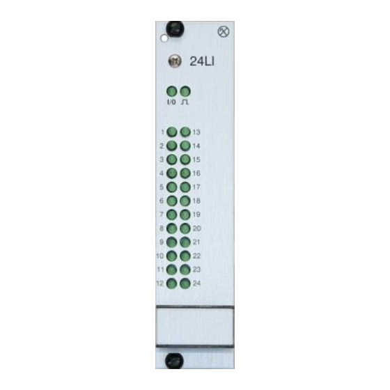
Page 51: 24Li
Detected input voltage 1-24 GREEN - FLASHING Output is enabled GREEN - OFF Idle state Backplane connectors: 1 - 24 Lines 02/2018 • V.1.0 • L. Wolle 51/131 ® Professional Communication & Service GmbH • Technical changes reserved. © 2017 ProCom... -
Page 52: Mi4M
GREEN - ON Ready power supply (48V) GREEN - OFF Fuse burn-out (48V) Line fuses Microfuse of the supply voltage for connected devices 02/2018 • V.1.0 • L. Wolle 52/131 ® Professional Communication & Service GmbH • Technical changes reserved. © 2017 ProCom... -
Page 53: Use1 (Rs232)
Program RS232 protocol only up to DVS Firmware 7.26 RS232 generally-used settings for a serial RS232 interface Programming takes place by means of the RS232 protocol program. 02/2018 • V.1.0 • L. Wolle 53/131 ® Professional Communication & Service GmbH • Technical changes reserved. © 2017 ProCom... -
Page 54: Operation Mode Loudspeaker Control (Aag - Vossloh)
CTS - CTS signal GND - Reference potential of the serial interface +0V - Reference potential of the 48V power supply 02/2018 • V.1.0 • L. Wolle 54/131 ® Professional Communication & Service GmbH • Technical changes reserved. © 2017 ProCom... -
Page 55: V100
The reference value of the measurement is only secured once it is stored in the configuration file. The configuration file must be transferred to the system, so that the impedance test can use with this value. 02/2018 • V.1.0 • L. Wolle 55/131 ® Professional Communication & Service GmbH • Technical changes reserved. © 2017 ProCom... -
Page 56: Acknowledgment
Line 22, Line 2 (PA acknowledgment) is activated (forwarding of the Line 22 CPU -> M acknowledgment in standby mode) Port 2 - 4: without function 02/2018 • V.1.0 • L. Wolle 56/131 ® Professional Communication & Service GmbH • Technical changes reserved. © 2017 ProCom... -
Page 57: Recommended Programs
(HG x). They have to be closed all or partially, but always in pairs. This photo shows the solder bridges for use with Standby amplifier! 02/2018 • V.1.0 • L. Wolle 57/131 ® Professional Communication & Service GmbH • Technical changes reserved. © 2017 ProCom... -
Page 58: Use2
Number of DTMF suffix digits Speech timer Time after which the connection is disconnected compulsorily Backplane connectors: T a/b - Line 02/2018 • V.1.0 • L. Wolle 58/131 ® Professional Communication & Service GmbH • Technical changes reserved. © 2017 ProCom... -
Page 59: Operation Mode Doorline
Byte 1 generated by the addition of the following values: (see also Hybrid balance) Hybrid amplification 0 - 31 Filter active/bypass 32 Byte 1 (Hybrid) negative overlap positive overlap 128 + 64 02/2018 • V.1.0 • L. Wolle 59/131 ® Professional Communication & Service GmbH • Technical changes reserved. © 2017 ProCom... - Page 60 The values of the limit, filter and switch can be transferred via the Online level! Backplane connection (Modem): T a/b - Line Backplane connection (PBX): T a/b - Line 02/2018 • V.1.0 • L. Wolle 60/131 ® Professional Communication & Service GmbH • Technical changes reserved. © 2017 ProCom...
-
Page 61: Operation Mode Lb
Online level automatically! This is merely an aid to filter adjustment. It is of no relevance in terms of the function! 02/2018 • V.1.0 • L. Wolle 61/131 ® Professional Communication & Service GmbH • Technical changes reserved. © 2017 ProCom... -
Page 62: Operation Mode Motorola Radio
Number of rings until pick-up Speech timer Time after which the call is disconnected automatically Backplane connectors: T a/b - Line 02/2018 • V.1.0 • L. Wolle 62/131 ® Professional Communication & Service GmbH • Technical changes reserved. © 2017 ProCom... -
Page 63: Tg01
Test 2 GREEN - ON Supply voltage available Al 1 RED - ON No function Al 1 RED - ON Earth leakage or bridge missing on backplane 02/2018 • V.1.0 • L. Wolle 63/131 ® Professional Communication & Service GmbH • Technical changes reserved. © 2017 ProCom... -
Page 64: 4Lsl
Public address is only possible if an impedance measurement is Enable after shortcut removal made without a short circuit 02/2018 • V.1.0 • L. Wolle 64/131 ® Professional Communication & Service GmbH • Technical changes reserved. © 2017 ProCom... -
Page 65: Temperature Profile
Important! Values transferred online are not stored permanently! Values determined must be stored in the programming and transferred to the system! 02/2018 • V.1.0 • L. Wolle 65/131 ® Professional Communication & Service GmbH • Technical changes reserved. © 2017 ProCom... - Page 66 Line 5 M -> CPU Short circuit at last measurement Line 6 M -> CPU No load at last measurement 02/2018 • V.1.0 • L. Wolle 66/131 ® Professional Communication & Service GmbH • Technical changes reserved. © 2017 ProCom...
- Page 67 RED - FLASHING (slow) excessive load (>150W) or no signal from TG01. Impedance error detected RED - ON (Tolerance exceeded) 02/2018 • V.1.0 • L. Wolle 67/131 ® Professional Communication & Service GmbH • Technical changes reserved. © 2017 ProCom...
-
Page 68: 4Dss
The configuration of UZ-ELA modules is done with Separate amplifier in the menu Call stations and devices. Backplane connectors: +/- - Power supply a/b - Line 02/2018 • V.1.0 • L. Wolle 68/131 ® Professional Communication & Service GmbH • Technical changes reserved. © 2017 ProCom... -
Page 69: 4Dae
Input, from the amplifier LK1 a/b Output 1 LK2 a/b Output 2 LK3 a/b Output 3 LK4 a/b Output 4 02/2018 • V.1.0 • L. Wolle 69/131 ® Professional Communication & Service GmbH • Technical changes reserved. © 2017 ProCom... -
Page 70: Call Stations And Devices
ProCom stations in 2-wire technology are connected to the 4DAV modules (4 per module). ProCom emergency call stations for the party line are connected at the module NSAPL (1-26 per module) The arrangement of keys/toggles on ProCom stations can be found in Appendix "Station keypads"! -
Page 71: General Data
Level of play back signal which is provided via the monitor input Ma/b into the call (only Desktop) station. All ProCom call stations can be operated with a 25 W Booster amplifier. The weatherproof call stations (WPSxx) have a built-in amplifier. Into the Desktop- Booster amplifier and Flush mount- call stations the external amplifier "BA-25"... -
Page 72: Third Party-Call Stations (Analog)
Programs module graphic. The dialog box of the program then opens for further configuration of the target or the function. 02/2018 • V.1.0 • L. Wolle 72/131 ® Professional Communication & Service GmbH • Technical changes reserved. © 2017 ProCom... -
Page 73: Pcs (Pc Call Station)
Volume/Level of the amplifier System call Integration in a system AllCall. (see AllCall) Online level Level is transferred to the amplifier 02/2018 • V.1.0 • L. Wolle 73/131 ® Professional Communication & Service GmbH • Technical changes reserved. © 2017 ProCom... -
Page 74: Measurement
Codec IC (with pins) µLaw and aLaw Codec IC (SMD) µLaw, aLaw and ADPCM (7kHz) 02/2018 • V.1.0 • L. Wolle 74/131 ® Professional Communication & Service GmbH • Technical changes reserved. © 2017 ProCom... -
Page 75: Alarm Lead 2
(see Examples 2-5) Alarm function with manual voice input This function is only possible on ProCom stations. Playback of alarm tones can be triggered. Voice input can be made in the running playback. Playback can be stopped. (see Example 1) - Page 76 Programming example: DSS1_PA_Alarm_1 Announcement with chime Programming example: DSS1_PA_Gong_1 - Targets with fixed assignment - Chime permanently programmed 02/2018 • V.1.0 • L. Wolle 76/131 ® Professional Communication & Service GmbH • Technical changes reserved. © 2017 ProCom...
- Page 77 Programming example: DSS1_PA_Gong_3, DSS1_PA_Gong_4 - Targets individually selectable - Chime programmed permanently *Dummy - see next example 02/2018 • V.1.0 • L. Wolle 77/131 ® Professional Communication & Service GmbH • Technical changes reserved. © 2017 ProCom...
-
Page 78: Fault Report Sequence 1
- an unused port of a 4NSA/4NPA - the port of the particular call station 9.3 Fault report sequence 1 Display and acknowledgment of a fault report on ProCom stations. Playback of recorded tones or speech from the DSS1 module (Operation mode Speech storage). -
Page 79: Ic Intercom
The remote station can reverse the direction and reply. The priorities can be the same. Own/Analog Selects the type of call station (ProCom- or Analog- call stations). Input/call station (Setting Own) Address and port of the module to which the call station is connected and the line Address, Port, Line (key) that is used. -
Page 80: Ic Intercom Door (Unilaterally-Controlled Intercom)
Handling of priorities (see Section 9.1) Own/Analog Selects the type of call station (ProCom or analog call stations). Input/call station (Setting Own) Address, Port, Address and port of the module to which the call station is connected and the line (key) Line that is used. -
Page 81: Ic Group
Interval time a selective call can be made by a subscriber replying. Own/Analog Selects the type of call station (ProCom or analog call stations). Input/call station (Setting Own) Address and port of the module to which the station is connected and the line Address, Port, Line (key) that is used. - Page 82 Announcements are suppressed within the feedback specific sub-group. Only stations (of the group) that are not members of the sub-group are controlled. 02/2018 • V.1.0 • L. Wolle 82/131 ® Professional Communication & Service GmbH • Technical changes reserved. © 2017 ProCom...
-
Page 83: Intercom Radio 2
Handling of priorities (see Section 9.1) Own/Analog Selects the type of call station (ProCom or analog call stations). Input/call station (Setting Own) Address and port of the module to which the call station is connected Address, Port, Line and the line (key) in use. (4NSA) - Page 84 Prevents monitoring the frequency band on the station. The AF is made Monitor loudspeaker audible by means of other programs or external devices. 02/2018 • V.1.0 • L. Wolle 84/131 ® Professional Communication & Service GmbH • Technical changes reserved. © 2017 ProCom...
-
Page 85: Intercom Radio Monitoring
AllCall No. ID of the connection Own/Analog Selects the type of call station (ProCom or analog call stations). Input/call station (Setting Own) Address and port of the module to which the call station is connected and the line Address, Port, Line (key) that is used. -
Page 86: Lb Connection
[OUT] The flag is connected if the the program is activated. This enables Flag (OUT) 1/2 further programs to be activated for adaptation to specific requirements. 02/2018 • V.1.0 • L. Wolle 86/131 ® Professional Communication & Service GmbH • Technical changes reserved. © 2017 ProCom... -
Page 87: Lb Forwarder
The options are: µLaw (default), ADPCM (7kHz) and aLaw (see Section 9.1) Own/Analog Selects the type of call station (ProCom or analog call stations). Input/call station (Setting Own) Address and port of the module to which the call station is connected and Address, Port, Line the line (key) that is used. -
Page 88: Public Address 2 "Pa Remote/Local
Busy message Specifications for transmission of busy message Call station selection - xxx Own/Analog Selects the type of call station (ProCom or analog call stations). Acknowledgment Type of display of a acknowledgment at the station Input/call station (Setting Own) Address and port of the module to which the call station is Address, Port, Line connected and the line (key) that is used. - Page 89 It is possible to hand over the AF channel in use. Busy flag [IO] Flag for processing of Busy status 02/2018 • V.1.0 • L. Wolle 89/131 ® Professional Communication & Service GmbH • Technical changes reserved. © 2017 ProCom...
-
Page 90: Af Switching
(see Section 4FTR) Remote - Intercom, Remote - Intercom forwarder Remote - Intercom Group programs are provided for system-wide intercom. 02/2018 • V.1.0 • L. Wolle 90/131 ® Professional Communication & Service GmbH • Technical changes reserved. © 2017 ProCom... -
Page 91: Remote - Intercom
Transmission via 2Mbps port for control and AF are identical) Own/Analog Selection of the type of call station (ProCom- or Analog- call stations). Input/call station (Setting Own) Address and port of the module to which the call station is connected and the Address, Port, Line line (key) that is used. -
Page 92: Remote - Intercom Group
Group programs. By using the Any option, it is also permitted for additional Remote - Intercom Group programs that are activated by a long-distance line. 02/2018 • V.1.0 • L. Wolle 92/131 ® Professional Communication & Service GmbH • Technical changes reserved. © 2017 ProCom... - Page 93 Busy status. [IN] The program can be turned off by this flag or switching on Flag (NAND) can be prevented. 02/2018 • V.1.0 • L. Wolle 93/131 ® Professional Communication & Service GmbH • Technical changes reserved. © 2017 ProCom...
-
Page 94: Remote - Allcall
AllCall No. ID of the connection Own/Analog Selects the type of call station (ProCom or analog call stations). Input/call station (Setting Own) Address and port of the module to which the call station is connected and the line Address, Port, Line (key) that is used. -
Page 95: Remote - Intercom Forwarder
Control lines The lines correspond with the Remote - Intercom program. 9.20 ZZ connection ZZ connection refers to a intercom connection between a DVS-21 and a analog third party system. The connection is made by means of a 4ZZA module. Priority... -
Page 96: Programs For Logic And Control
Address, port and line to a module Output (invers) Address, port and line to a module (ON in idle position) 02/2018 • V.1.0 • L. Wolle 96/131 ® Professional Communication & Service GmbH • Technical changes reserved. © 2017 ProCom... -
Page 97: Special Input (Selection Box)
At least one Flag (OR) or at least two Flag (AND) must be active in order for the output to be active as well. The Flag 255 (Always ON)is available for continuous activation. 02/2018 • V.1.0 • L. Wolle 97/131 ® Professional Communication & Service GmbH • Technical changes reserved. © 2017 ProCom... -
Page 98: Input Conditions
Time runs from start Timer 2 Follow-up time, time runs from end Timer 3 Trigger Timer 4 Combination of delay and follow-up 02/2018 • V.1.0 • L. Wolle 98/131 ® Professional Communication & Service GmbH • Technical changes reserved. © 2017 ProCom... -
Page 99: Flag Timing
Address, Port, Line The LED flashes when measurement is active. The LED glows continuously in the event of a measurement fault. 02/2018 • V.1.0 • L. Wolle 99/131 ® Professional Communication & Service GmbH • Technical changes reserved. © 2017 ProCom... -
Page 100: Level Control (Loud/Quiet)
10.5 Level control (loud/quiet) Placing loud/quiet soft function (keys) on a station, to change level (Codec setting) of any module. Note! Not to be confused with the loud/quiet soft function of ProCom stations! Input Address and port of the module to which the call station is connected, from which the Address, Port level is to be changed. -
Page 101: Operation Mode Control (Mi4M) (Automatic Gain Control)
Address and port of the module, the level(Codec setting) of which is to be set. 4NSA/4NPA or V100 Internal amplifier V100 or external amplifier on 4NPA 02/2018 • V.1.0 • L. Wolle 101/131 ® Professional Communication & Service GmbH • Technical changes reserved. © 2017 ProCom... -
Page 102: Measurements/Simulation
Sends the set level value to the amplifier. Reference: detailed description of the measuring process in the document "MI4M Start-up" 02/2018 • V.1.0 • L. Wolle 102/131 ® Professional Communication & Service GmbH • Technical changes reserved. © 2017 ProCom... -
Page 103: Lb Splitter
[IN] The program can be switched on by this flag. [OUT] The flag is switched on if the program is activated. Other programs can be Flag (OUT) 1/2 triggered. 02/2018 • V.1.0 • L. Wolle 103/131 ® Professional Communication & Service GmbH • Technical changes reserved. © 2017 ProCom... -
Page 104: Contact Switch
Address, port and line Expansion of the range from 120 to 255 lines by using special lines. (only on Long distance line line pool own long-distance lines between ProCom systems) Flashing (call station / 24Li) Use of the Flashing (only stations/24LI)line type... -
Page 105: Line Block Trigger
Port-Interval time Pause until the next port is processed (Unit: Seconds) Program-Interval time Pause until the program is resumed (Unit: Seconds) 02/2018 • V.1.0 • L. Wolle 105/131 ® Professional Communication & Service GmbH • Technical changes reserved. © 2017 ProCom... -
Page 106: Byte Edit (Universal32)
Available programs can be opened with his dialog via the right-hand mouse menu (Dataset). An empty dialog is opened for a new dataset via the selection of the programs in the module Programs. 02/2018 • V.1.0 • L. Wolle 106/131 ® Professional Communication & Service GmbH • Technical changes reserved. © 2017 ProCom... -
Page 107: Anhang
User Guide DVS-21 11 Attachment 11.1 SV01 02/2018 • V.1.0 • L. Wolle 107/131 ® Professional Communication & Service GmbH • Technical changes reserved. © 2017 ProCom... -
Page 108: Cpu
User Guide DVS-21 11.2 CPU 02/2018 • V.1.0 • L. Wolle 108/131 ® Professional Communication & Service GmbH • Technical changes reserved. © 2017 ProCom... -
Page 109: Lcpu
User Guide DVS-21 11.3 LCPU 02/2018 • V.1.0 • L. Wolle 109/131 ® Professional Communication & Service GmbH • Technical changes reserved. © 2017 ProCom... -
Page 110: 4Ftr
User Guide DVS-21 11.4 4FTR 02/2018 • V.1.0 • L. Wolle 110/131 ® Professional Communication & Service GmbH • Technical changes reserved. © 2017 ProCom... - Page 111 User Guide DVS-21 02/2018 • V.1.0 • L. Wolle 111/131 ® Professional Communication & Service GmbH • Technical changes reserved. © 2017 ProCom...
-
Page 112: 4Nsa
User Guide DVS-21 11.5 4NSA 02/2018 • V.1.0 • L. Wolle 112/131 ® Professional Communication & Service GmbH • Technical changes reserved. © 2017 ProCom... -
Page 113: 4Dav
User Guide DVS-21 11.6 4DAV 02/2018 • V.1.0 • L. Wolle 113/131 ® Professional Communication & Service GmbH • Technical changes reserved. © 2017 ProCom... -
Page 114: 4Npa
User Guide DVS-21 11.7 4NPA 02/2018 • V.1.0 • L. Wolle 114/131 ® Professional Communication & Service GmbH • Technical changes reserved. © 2017 ProCom... -
Page 115: 4Zza
User Guide DVS-21 11.8 4ZZA 02/2018 • V.1.0 • L. Wolle 115/131 ® Professional Communication & Service GmbH • Technical changes reserved. © 2017 ProCom... -
Page 116: 4Ios
User Guide DVS-21 11.9 4IOS 02/2018 • V.1.0 • L. Wolle 116/131 ® Professional Communication & Service GmbH • Technical changes reserved. © 2017 ProCom... -
Page 117: 24Li
User Guide DVS-21 11.10 24LI 02/2018 • V.1.0 • L. Wolle 117/131 ® Professional Communication & Service GmbH • Technical changes reserved. © 2017 ProCom... -
Page 118: Mi4M
User Guide DVS-21 11.11 MI4M 02/2018 • V.1.0 • L. Wolle 118/131 ® Professional Communication & Service GmbH • Technical changes reserved. © 2017 ProCom... -
Page 119: Use1 (Rs232)
User Guide DVS-21 11.12 USE1 (RS232) 02/2018 • V.1.0 • L. Wolle 119/131 ® Professional Communication & Service GmbH • Technical changes reserved. © 2017 ProCom... -
Page 120: V100
User Guide DVS-21 11.13 V100 02/2018 • V.1.0 • L. Wolle 120/131 ® Professional Communication & Service GmbH • Technical changes reserved. © 2017 ProCom... - Page 121 User Guide DVS-21 02/2018 • V.1.0 • L. Wolle 121/131 ® Professional Communication & Service GmbH • Technical changes reserved. © 2017 ProCom...
-
Page 122: Use2
User Guide DVS-21 11.14 USE2 02/2018 • V.1.0 • L. Wolle 122/131 ® Professional Communication & Service GmbH • Technical changes reserved. © 2017 ProCom... - Page 123 User Guide DVS-21 02/2018 • V.1.0 • L. Wolle 123/131 ® Professional Communication & Service GmbH • Technical changes reserved. © 2017 ProCom...
- Page 124 User Guide DVS-21 02/2018 • V.1.0 • L. Wolle 124/131 ® Professional Communication & Service GmbH • Technical changes reserved. © 2017 ProCom...
-
Page 125: Tg01
User Guide DVS-21 11.15 TG01 02/2018 • V.1.0 • L. Wolle 125/131 ® Professional Communication & Service GmbH • Technical changes reserved. © 2017 ProCom... -
Page 126: 4Lsl
User Guide DVS-21 11.16 4LSL 02/2018 • V.1.0 • L. Wolle 126/131 ® Professional Communication & Service GmbH • Technical changes reserved. © 2017 ProCom... -
Page 127: 4Dss
User Guide DVS-21 11.17 4DSS 02/2018 • V.1.0 • L. Wolle 127/131 ® Professional Communication & Service GmbH • Technical changes reserved. © 2017 ProCom... -
Page 128: 4Dae
User Guide DVS-21 11.18 4DAE 02/2018 • V.1.0 • L. Wolle 128/131 ® Professional Communication & Service GmbH • Technical changes reserved. © 2017 ProCom... -
Page 129: Station Keypads
11.19 Station Keypads DTA (12, 48, 66, 84, 114) WPS 04 + AWC 06 (4, 10, 16, 22, 28, 34) 02/2018 • V.1.0 • L. Wolle 129/131 ® Professional Communication & Service GmbH • Technical changes reserved. © 2017 ProCom... -
Page 130: Wps 08 + Awc 06 (8, 14, 20, 26, 32, 38)
DVS-21 WPS 08 + AWC 06 (8, 14, 20, 26, 32, 38) PMS/PMK 16 (16, 32, 48, 64, 80, 96) 02/2018 • V.1.0 • L. Wolle 130/131 ® Professional Communication & Service GmbH • Technical changes reserved. © 2017 ProCom... -
Page 131: Dta-Lan (24, 78, 132, 186, 240)
User Guide DVS-21 DTA-LAN (24, 78, 132, 186, 240) 02/2018 • V.1.0 • L. Wolle 131/131 ® Professional Communication & Service GmbH • Technical changes reserved. © 2017 ProCom...
Need help?
Do you have a question about the DVS-21 and is the answer not in the manual?
Questions and answers