Table of Contents
Advertisement
Quick Links
Advertisement
Table of Contents

Subscribe to Our Youtube Channel
Related Manuals for Ametek CSC201


Summary of Contents for Ametek CSC201
- Page 1 User Manual Compact Signal Calibrator CSC201...
-
Page 2: Table Of Contents
1.1 Contacting Ametek........ -
Page 3: Introduction
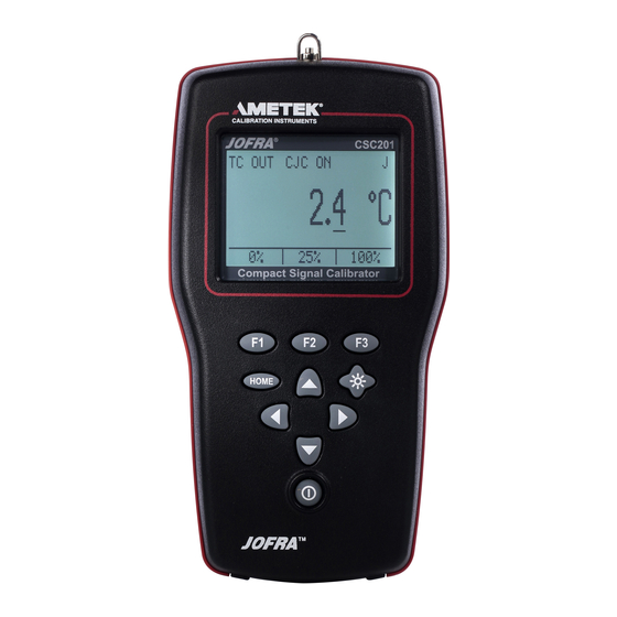
1. Introduction The AMETEK CSC201 Compact Signal Calibrator is a handheld, battery- operated instrument that measures and simulates physical and electrical parameters. The calibrator has the following features and functions: • A large easy to read display used to display all supported physical and electrical parameters. -
Page 4: Safety Information
1.3 Safety information Symbols Used The following table lists the International Electrical Symbols. Some or all of these symbols may be used on the instrument or in this manual. Symbol Description AC (Alternating Current) AC-DC Battery CE Complies with European Union Directives Double Insulated Electric Shock Fuse... - Page 5 Warning The CSC201 is designed to calibrate and measure low voltage process signals. To ensure the safety of the operator, DO NOT connect the CSC201 to inputs greater than 30 Volts. Warning To avoid possible electric shock or personal injury: •...
- Page 6 • When using a pressure module, make sure the process pressure line is shut off and depressurized before you connect it or disconnect it from the pressure module. • Disconnect test leads before changing to another measure or source function. •...
-
Page 7: Calibrator Interface
2. Calibrator Interface Figure 1 shows the location of the input and output connections on the calibrator, while Table 1 describes their use. HOME Figure 1. Input/Output Terminals Table 1: Input and Output Terminals Name Description TC input/output Terminal for measuring, or simulating thermocouples. Accepts miniature polarized thermocouple plugs with flat in-line blades spaced 7.9 mm (0.312 in) center to center. - Page 8 Figure 2 shows the location of the keys on the calibrator. Table 2 lists the functions of each key. HOME Figure 2. Keypad Table 2. Key Functions Name Function Function Keys These keys are used in various ways, primarily to con- figure the calibrator ON/OFF Key This key is used to turn the calibrator on and off...
-
Page 9: Main Display
2.1 Main Display RTD IN 4W P100(90)385 0.0 °C CONFIG MORE Figure 3. Display The display of the calibrator, shown in Figure 3, is divided into two sections: the main display and the menu bar. The main display is used for both measuring and sourcing. The menu bar is used to setup the display to perform the desired function. - Page 10 2.2 Menu Bar The parameters on the display are controlled by the menu bar, which is located at the bottom of the LCD. The function keys (F1, F2, and F3) are used to navigate through all the levels and choices of the menu bar. Refer to the menu tree for a clarification on the layout of all the levels.
- Page 11 AUTO FUNC NEXT DONE When the calibrator is in any source mode, the auto output main menu is added. The options available on this menu are [AUTO FUNC], [NEXT] and [DONE]. The [AUTO FUNC] option allows you to turn the RAMP/STEP functions on or off.
- Page 12 Home Menu CONFIG MORE Parameter Selection If calibrator is in If calibrator is in SELECT NEXT DONE Source mode Measure mode Home Menu Auto Output Main Menu CONFIG MORE AUTO FUNC NEXT DONE Contrast Menu CONTRAST NEXT DONE Home Menu CONFIG MORE Auto Off Menu...
-
Page 13: Using Measure Modes
3. Using Measure Modes TC IN CJC ON 3.1 Measuring Temperature 0.0 °C 3.1-1 Using Thermocouples The calibrator supports the following thermocouple types: B, C, E, J, K, L, N, R, S, T, U, BP , and XK. The characteristics of MORE CONFIG all the types are described in the... -
Page 14: Measuring Pressure
3.1-2 Using Resistance-Temperature-Detectors (RTDs) The supported types of RTDs are shown in the Specifications section. RTDs are characterized by their 0°C resistance, R0. The calibrator accepts two, three, and four wire inputs, with four wire input being the most accurate. To use the RTD option, apply the following steps: Press [CONFIG] to enter the configuration mode.. - Page 15 Caution To avoid mechanically damaging the pressure module, never apply more than 13.5 Nm/10 ftlbs. of torque between the pressure module fittings, or between the fittings an the body of the module. To avoid damaging the pressure module from overpressure, never apply pressure above the rated maximum printed on the module.
-
Page 16: Using Source Modes
1. Select [ZERO ]. [SET REFERENCE ABOVE] will appear. Enter the pressure using the cursor keys. 2. The calibrator stores the Barometric zero offset in non-volatile memory. The zero offset is stored for one absolute pressure module at a time. If a new absolute module is connected this process must be repeated. -
Page 17: Sourcing Thermocouples
– TC PLUG Note: TC wire used must match the thermocouple type being calibrated. – Figure 8. Connections for Outputting Thermocouples 4.3 Sourcing Thermocouples To source a thermocouple use the following steps: 1. Connect the thermocouple leads to the appropriate polarized TC miniplug, and insert the plug into the TC terminals on the calibrator, as shown in Figure 8. -
Page 18: Sourcing Ohms/Rtds
4.4 Sourcing Ohms/RTDs To source an RTD, follow these steps: 1. Press [CONFIG] and choose [RTD] from the primary parameters. 2. Choose output [OUT] from the input/output control, and select RTD type from the sensor types. 3. Connect the calibrator to the instrument being tested, as in Figure 19. 4. - Page 19 4.4-1 Custom RTD A custom curve-fit PRT may be entered into the calibrator for sourcing and measuring. To do so follow these steps: 1. Switch to lower display. Select RTD and set sensor type to CUSTOM. 2. Custom Coefficients can only be entered through the serial port. The custom function uses the Calendar-Van Dusen equation for outputting and measuring custom RTDs.
-
Page 20: Remote Operation
5. Remote Operation The calibrator can be remotely controlled using a PC terminal, or by a computer program running the calibrator in an automated system. It uses an RS232 serial port connection for remote operation. With this connection the user can write programs on the PC, with Windows languages like Visual Basic to operate the calibrator, or use a Windows terminal, such as Hyper Terminal, to enter single commands. -
Page 21: Specifications
6. Specifications One year at 23°C ± 5°C, unless specified otherwise. Outside of this range the stability of the measurements is ± 0.003% of FS/°C. Table 5: General Specifications Operating Temperature -10°C to 50°C Storage Temperature -20°C to 60°C Power 4 X AA batteries;... - Page 22 Table 9: Thermocouple Read and Source (errors in °C) Range (°C) Accuracy (°C) TC Type Minimum Maximum CJC OFF CJC ON -210.0 -150.0 -150.0 1200.0 -200.0 -100.0 -100.0 600.0 600.0 1000.0 1000.0 1372.0 -250.0 -200.0 -200.0 400.0 -250.0 -200.0 -200.0 -100.0 -100.0 1000.0...
- Page 23 Table 10: RTD Read and Source RTD Type Range (°C) Accuracy (°C) 1 year Minimum Maximum Measure Measure 4W/Source P10(90)385 -200 0.85 2.20 1.00 2.50 1.20 2.80 P50(90)385 -200 0.20 0.50 0.30 0.60 0.40 0.70 P100(90)385 -200 0.15 0.25 0.20 0.35 0.30 0.45...
-
Page 24: Maintenance
Table 11: Pressure Measurement Units Engineering Unit Factor 0.06894757 mbar 68.94757 6.894757 0.00689476 kg/cm2 0.07030697 cmH2O @ 4°C 70.3089 cmH2O @ 20°C 70.4336 mmH2O @ 4 °C 703.089 mmH2O @ 20°C 704.336 inH2O @ 4°C 27.68067 inH2O @ 20°C 27.72977 inH2O @ 60°F 27.70759 mmHg @ 0°C... -
Page 25: Service Center Calibration Or Repair
Caution To avoid damaging the plastic lens and case, do not use solvents or abrasive cleansers. Clean the calibrator with a soft cloth dampened with water or water and mild soap. 7.3 Service Center Calibration or Repair Only qualified service personnel should perform calibration, repairs, or servicing not covered in this manual. - Page 26 AMETEK Instruments India Pvt Ltd. Tel +86 20 8363 4768 Tel +49 (0)2159 9136 510 Tel +91 22 2836 4750 lloyd@ametek.com.cn info.mct-de@ametek.de jofra@ametek.com Information in this document is subject to change without notice. ©2012, by AMETEK, Inc., www.ametek.com. All rights reserved.
Need help?
Do you have a question about the CSC201 and is the answer not in the manual?
Questions and answers