Table of Contents
Advertisement
Quick Links
Advertisement
Table of Contents

Related Manuals for Siemens Sinamics Connect Series


Summary of Contents for Siemens Sinamics Connect Series
- Page 3 ___________________ Preface ___________________ Safety instructions ___________________ SINAMICS Overview ___________________ Mounting SINAMICS CONNECT ___________________ Connecting ___________________ Configuring the device Operating Instructions ___________________ Getting connected to MindSphere ___________________ Maintaining and repairing the device ___________________ Technical specifications ___________________ Appendix Software 1.0.0 10/2018 A5E45421408...
- Page 4 Note the following: WARNING Siemens products may only be used for the applications described in the catalog and in the relevant technical documentation. If products and components from other manufacturers are used, these must be recommended or approved by Siemens. Proper transport, storage, installation, assembly, commissioning, operation and maintenance are required to ensure that the products operate safely and without any problems.
-
Page 5: Preface
Reference You can find the overview of documentation and links to download documents as well as to use documentation online at: More information (https://support.industry.siemens.com/cs/ww/en/ps/25436/man). Product maintenance The components are subject to continuous further development within the scope of product maintenance (improvements to robustness, discontinuations of components, etc). - Page 6 Siemens does not accept any warranty for the properties of third-party products. Compliance with the General Data Protection Regulation Siemens respects the principles of data protection, in particular the data minimization rules (privacy by design). For this product, this means: The product does not process neither store any person-related data, only technical function data (e.g.
-
Page 7: Table Of Contents
Table of contents Preface ..............................3 Safety instructions ............................. 8 Fundamental safety instructions ....................8 1.1.1 General safety instructions ....................... 8 1.1.2 Equipment damage due to electric fields or electrostatic discharge ........13 1.1.3 Warranty and liability for application examples ..............13 1.1.4 Industrial security ........................ - Page 8 Table of contents 5.2.1.1 Logging in ..........................38 5.2.1.2 Changing the default password ..................... 39 5.2.1.3 Setting security questions ...................... 40 5.2.2 Normal login ........................... 41 5.2.2.1 Logging in ..........................41 5.2.2.2 Retrieving the password ......................42 5.2.3 Home page ..........................44 5.2.3.1 Overview ..........................
- Page 9 Table of contents Technical data ......................... 85 8.4.1 General technical specifications ..................... 85 8.4.2 Ambient conditions ........................86 8.4.3 Power demand of the components ..................87 8.4.4 Direct current power supply (DC) ................... 87 8.4.5 Address of CE-authorized manufacturer ................88 Hardware description ......................
-
Page 10: Safety Instructions
Safety instructions Fundamental safety instructions 1.1.1 General safety instructions WARNING Electric shock and danger to life due to other energy sources Touching live components can result in death or severe injury. • Only work on electrical devices when you are qualified for this job. •... - Page 11 Safety instructions 1.1 Fundamental safety instructions WARNING Risk of electric shock and fire from supply networks with an excessively low impedance Excessively high short-circuit currents can lead to the protective devices not being able to interrupt these short-circuit currents and being destroyed, and thus causing electric shock or a fire.
- Page 12 Safety instructions 1.1 Fundamental safety instructions WARNING Arcing when a plug connection is opened during operation Opening a plug connection when a system is operation can result in arcing that may cause serious injury or death. • Only open plug connections when the equipment is in a voltage-free state, unless it has been explicitly stated that they can be opened in operation.
- Page 13 • If you come closer than around 2 m to such components, switch off any radios or mobile phones. • Use the "SIEMENS Industry Online Support app" only on equipment that has already been switched off. NOTICE...
- Page 14 Safety instructions 1.1 Fundamental safety instructions NOTICE Device damage caused by incorrect voltage/insulation tests Incorrect voltage/insulation tests can damage the device. • Before carrying out a voltage/insulation check of the system/machine, disconnect the devices as all converters and motors have been subject to a high voltage test by the manufacturer, and therefore it is not necessary to perform an additional test within the system/machine.
-
Page 15: Equipment Damage Due To Electric Fields Or Electrostatic Discharge
Safety instructions 1.1 Fundamental safety instructions 1.1.2 Equipment damage due to electric fields or electrostatic discharge Electrostatic sensitive devices (ESD) are individual components, integrated circuits, modules or devices that may be damaged by either electric fields or electrostatic discharge. NOTICE Equipment damage due to electric fields or electrostatic discharge Electric fields or electrostatic discharge can cause malfunctions through damaged individual components, integrated circuits, modules or devices. -
Page 16: Industrial Security
Siemens’ products and solutions undergo continuous development to make them more secure. Siemens strongly recommends that product updates are applied as soon as they are available and that the latest product versions are used. Use of product versions that are no longer supported, and failure to apply the latest updates may increase customer’s exposure... -
Page 17: Residual Risks Of Power Drive Systems
Safety instructions 1.1 Fundamental safety instructions 1.1.5 Residual risks of power drive systems When assessing the machine- or system-related risk in accordance with the respective local regulations (e.g., EC Machinery Directive), the machine manufacturer or system installer must take into account the following residual risks emanating from the control and drive components of a drive system: 1. -
Page 18: Additional Safety Instructions
Safety instructions 1.2 Additional safety instructions Additional safety instructions 1.2.1 General safety instructions WARNING Life-threatening voltages due to use of an open control cabinet When you install the device in a control cabinet, some areas or components in the open control cabinet may be carrying life-threatening voltages, which may result in death or serious injury. -
Page 19: Notes On Use
Safety instructions 1.2 Additional safety instructions 1.2.2 Notes on use Note Possible functional restrictions in case of non-validated plant operation The device is tested and certified on the basis of the technical standards. In rare cases, functional restrictions can occur during plant operation. •... -
Page 20: Overview
Overview The SINAMICS CONNECT is designed to acquire data through the serial port on the converter and synchronize the data to MindSphere, the Siemens Industrial IoT operating system. The SINAMICS CONNECT can be used to connect the following converters to MindSphere: ●... -
Page 21: Structure Of The Device
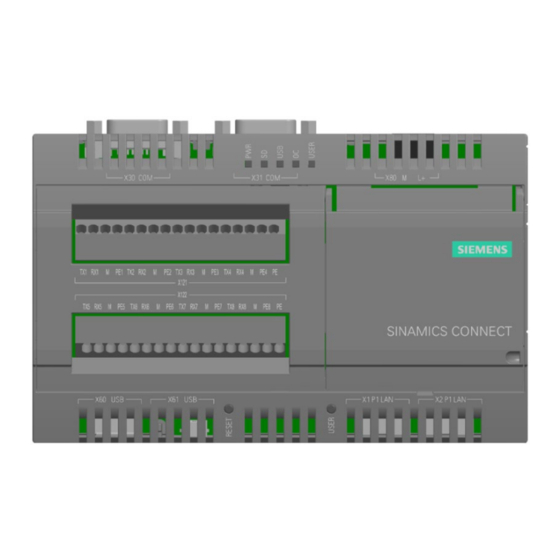
Overview 2.2 Structure of the device Structure of the device Top view Front view Bottom view ① ⑧ Openings for push-in lugs for wall Securing device mounting ② ⑨ Power supply connector RESET button for the CPU ③ ⑩ COM interfaces (reserved) USER button ④... -
Page 22: Scope Of Delivery
Overview 2.3 Scope of delivery Scope of delivery Check the scope of delivery for completeness and intactness: ● One SINAMICS CONNECT device with one DC terminal block mounted ● Quick Install Guide in English Note The device contains open-source software (OSS). The OSS license terms are saved in the device. - Page 23 Overview 2.3 Scope of delivery Serial number explanation (example) SINAMICS CONNECT Operating Instructions, 10/2018, A5E45421408...
-
Page 24: Accessories
Overview 2.4 Accessories Accessories The following accessory is not included in the scope of delivery and can be ordered separately. Industry Mall (https://mall.industry.siemens.com) Push-in lugs Set with 100 push-in lugs for wall mounting Article number: 3RB1900-0B SINAMICS CONNECT Operating Instructions, 10/2018, A5E45421408... -
Page 25: Mounting
Mounting Preparing for installation 3.1.1 Checking the delivery Procedure 1. When accepting a delivery, please check the packaging for visible transport damage. 2. If any transport damage is present at the time of delivery, lodge a complaint at the shipping company in charge. Have the shipper confirm the transport damage immediately. -
Page 26: Permitted Mounting Orientation And Mounting Types
Mounting 3.1 Preparing for installation NOTICE Damage from condensation If the device is subjected to low temperatures or extreme fluctuations in temperature during transportation, for example in cold weather, moisture could build up on or inside the HMI device (condensation). Moisture causes a short circuit in electrical circuits and damages the device. -
Page 27: Mounting The Device
Mounting 3.2 Mounting the device Clearances Make sure that the following clearances to another component or to the wall of a housing are complied with: ● Both above and below the device: ≥ 50 mm Mounting the device Protection against the spread of fire The device may be operated only in closed housings or in control cabinets with protective covers that are closed, and when all of the protective devices are used. -
Page 28: Mounting Instructions
Mounting 3.2 Mounting the device 3.2.1 Mounting instructions Note the following: ● The device is approved for indoor operation only. ● For installation in a cabinet, observe the relevant DIN/VDE requirements or the applicable country-specific regulations. ● When the device is used in the area of Industrial Control Equipment in accordance with UL61010-2-201, note that the device is classified as "Open Type". -
Page 29: Mounting On Din Rails
Mounting 3.2 Mounting the device 3.2.2 Mounting on DIN rails Requirement ● A DIN rail, 35 mm standard profile The DIN rail is installed at the installation site. Procedure Mounting 1. Place the device and rail clip on the upper edge of the standard profile rail at the position shown and push the device down. - Page 30 Mounting 3.2 Mounting the device Procedure 1. Guide a push-in lug through the corresponding opening at the top of the device, as shown in the figure. 2. Press the push-in lug down. 3. Mark the bore holes, drill the required holes in the wall and fasten the device to the wall using four screws and corresponding anchors.
-
Page 31: Connecting
Connecting Connecting the device 4.1.1 Notes on connecting WARNING Personal injury due to lightning strikes A lightning flash may enter the mains cables and data transmission cables and jump to a person, which may cause death, serious injury and burns. •... -
Page 32: Connecting The Power Supply
Connecting 4.1 Connecting the device NOTICE Ferrite required at USB cables The interference immunity of the device according to the data in the technical specifications is only guaranteed when the cables at USB and micro USB ports are equipped with a ferrite magnet. - Page 33 Connecting 4.1 Connecting the device 3. Insert the terminal to the indicated position. 4. Switch on the power supply, the "PWR" LED will light up green. SINAMICS CONNECT Operating Instructions, 10/2018, A5E45421408...
-
Page 34: Connecting The Device To Mindsphere Network
Connecting 4.1 Connecting the device 4.1.3 Connecting the device to MindSphere network Connect the device to the MindSphere network via interface X1. Interface IP address Description DHCP address RJ45 Ethernet connection 2 for 10/100 Mbps. Access to the Inter- net (to MindSphere). Required to get connected to MindSphere. -
Page 35: Securing The Cables
Connecting 4.2 Connecting the converter to the device Note The length of the Ethernet cable must be less than 30 m or the communication will be unstable. 4.1.5 Securing the cables Use cable ties or cable clamps to secure the connected cables to suitable fixing elements for strain relief. - Page 36 The following takes SINAMICS V20 and X121 port 1 as an example to indicate the wiring between the converter and the SINAMICS CONNECT. Note To achieve better EMC performance, Siemens recommends you to observe the following when connecting the converter: • Use the shielded cable for RS232 communication between the converter and the device.
- Page 37 2. Insert the cable from above. 3. Release the screwdriver after the cable is inserted in the indicated position. Note Siemens recommends that you use the signal cable with a length less than 3 m. SINAMICS CONNECT Operating Instructions, 10/2018, A5E45421408...
-
Page 38: Identifying The Converter (Optional)
Connecting 4.2 Connecting the converter to the device 4.2.2 Identifying the converter (optional) The SINAMICS CONNECT supports port modes of "Auto" and "Manual" which you can set via the SINAMICS CONNECT Web server. For more information, see Section "Configuring ports (Page 50)". ●... -
Page 39: Configuring The Device
Safari version 12.0 or later • Siemens recommends that you use the Web browsers listed above to achieve optimum Web browsing performance. Requirement Make sure that the device and your PC are on a common Ethernet network or are connected directly to each other with a standard Ethernet cable. -
Page 40: Standard Web
Configuring the device 5.2 Standard Web pages Standard Web pages 5.2.1 First login 5.2.1.1 Logging in In the case of the first login, after you enter the URL of the SINAMICS CONNECT Web address, the Web browser goes to the first login page. Requirement ●... -
Page 41: Changing The Default Password
Configuring the device 5.2 Standard Web pages 5.2.1.2 Changing the default password Requirement ● You have logging in the Web server successfully for the first time. Procedure 1. Enter a new password in the "New Password" input field. Note To protect against unauthorized access, by an attacker, for example, select a password that is as secure as possible. -
Page 42: Setting Security Questions
Configuring the device 5.2 Standard Web pages 2. Repeat the password in the "Repeat Password" input field. Note: If the two inputs are inconsistent, the background of the two input fields becomes red, which results in a saving failure. 3. Click "Save" to activate the password changing. Note: Only a password of the medium level or higher can be saved successfully. -
Page 43: Normal Login
Configuring the device 5.2 Standard Web pages 4. Click "Save" to activate your settings. Note You must set totally four security questions, three of which will be asked when you forget your password. Only when you give right answers for all the three questions, you are allowed to enter a new password. -
Page 44: Retrieving The Password
Configuring the device 5.2 Standard Web pages Procedure 1. Enter the user name and password in the "Username" and "Password" input fields respectively. 2. Click “Login” to log in to the Web server. Result ● If you enter the correct user name and a password other than "Admin", the Web browser brings you to the home page (Page 44). - Page 45 Configuring the device 5.2 Standard Web pages 3. Click "Next". 4. Answer totally three security questions correctly. Then click “Next”. Note: Only when you give the same answer as when you set the security question for all of the three questions, you can proceed with the next step; otherwise, the background of the three input fields becomes red, prompting you to give the right answer.
-
Page 46: Home Page
The Web pages display a representation of the converter to which you are connected and lists all the Web page operations that the Web server supports. Home page Web page header area ① ④ Siemens logo Changing security questions (Page 59) ② ⑤ User name Logging out (Page 60) ③... -
Page 47: Viewing The Port Information
Configuring the device 5.2 Standard Web pages Hierarchy of the main navigation bar Clicking one of the icons in the main navigation bar expands/collapses its menu and sub- menus (if any). 5.2.3.2 Viewing the port information See below for structure of the information display area of a port on the home page: ①... -
Page 48: Quick Configuration
Configuring the device 5.2 Standard Web pages Viewing the connection status ① You can view the connection status ( in the above figure) of each port from the status indicator light in the upper-right corner of the information display area of the port. Light Status Description... - Page 49 Configuring the device 5.2 Standard Web pages 1. On the quick configuration home page, activate (for example) port 1 via the check box. Note: By default, all the eight ports are activated. 2. Click the toggle button to select the port mode for port 1. –...
- Page 50 Configuring the device 5.2 Standard Web pages 8. Set the sampling period (an integer equal to or greater than 1) in the "Sample Cycle" input field. The period is measured in seconds. (Repeat steps 7 and 8 to set other one or more parameters as desired.) 9.
- Page 51 Configuring the device 5.2 Standard Web pages 14. Click "Apply" to save the settings. 15. In the window that opens, click “Browse” to navigate to and select the local configuration file (.txt). Note: The .txt file is produced from the onboarding key value that is downloaded from MindSphere.
-
Page 52: Acquiring The Converter Data
Configuring the device 5.2 Standard Web pages 18. Click “Next” to view the port configuration results. – Button a: jumps back to the quick configuration home page for you to make further modifications. – Button b: discards all the settings and brings you back to the home page. –... - Page 53 Configuring the device 5.2 Standard Web pages Procedure 1. Choose the "Port Configuration" menu from the home page. 2. Activate (for example) port 1 via the check box. Note: On the port configuration home page, all the eight ports are displayed and activated by default.
- Page 54 Configuring the device 5.2 Standard Web pages 7. The Web browser jumps back to the port configuration home page. Click “Parameters” to start setting converter parameters. 8. In the window that opens, activate (for example) parameter 1 via the check box. 9.
-
Page 55: Configuring Mindsphere
Configuring the device 5.2 Standard Web pages 13. After checking the port configuration results that display, click button c to submit the settings. Result The Web browser jumps back to the home page. 5.2.5.2 Configuring MindSphere Requirement ● You have accessed the home page after a successful normal login. Note Before configuring MindSphere, make sure that you have produced the configuration file (.txt) from the onboarding key value that is downloaded from MindSphere. - Page 56 Configuring the device 5.2 Standard Web pages 5. On the MindSphere configuration home page, click “Browse” to navigate to and select the local configuration file (.txt). Note: The .txt file is produced from the onboarding key value that is downloaded from MindSphere.
-
Page 57: Optional Setting Pages
Configuring the device 5.2 Standard Web pages 5.2.6 Optional setting pages On the optional setting pages, you are allowed to complete the following device related settings: ● Rebooting the device (Page 55) ● Upgrading (Page 55) ● Downloading system logs (Page 56) ●... -
Page 58: Downloading System Logs
Procedure 1. Download the upgrade file (.zip) from the customer support Web site (https://support.industry.siemens.com/cs/ww/en/ps/25436) to the local drive on your PC. 2. Choose the "Update Software" menu from the navigation bar. 3. On the upgrading home page, click “Browse” to navigate to and select the local upgrade file (.zip). -
Page 59: Synchronizing Time
Configuring the device 5.2 Standard Web pages Requirement ● You have accessed the home page after a successful normal login. Procedure 1. Choose the "Download System Log" menu from the navigation bar. 2. On the system log home page, click “Download” to save the log file (.txt) to the local drive on your PC. - Page 60 Configuring the device 5.2 Standard Web pages Note: You can also enter the local time manually in the "Proofreading Time" input field, and then select the desired time zone from the "Time Zone" drop-down list. Note Make sure that you set the local time accurately (permissible time error: ±2 minutes). Improper settings with a time error of greater than 2 minutes may cause a failure of data transfer.
-
Page 61: Account Related Settings
Configuring the device 5.2 Standard Web pages Result The system time is synchronized successfully. Now you are logged out and requested to log back in for further operations in the Web server. 5.2.7 Account related settings 5.2.7.1 Changing the password You can choose to change the password from the drop-down list in the upper-right corner of any page that displays after you have logged in successfully. -
Page 62: Logging Out
Configuring the device 5.2 Standard Web pages Procedure 1. Hover on the user name in the upper-right corner of the Web page. 2. Select “Security Question” from the drop-down list. 3. Change security questions by following the steps described in Section “Setting security questions (Page 40)”. -
Page 63: Getting Connected To Mindsphere
Getting connected to MindSphere Overview MindSphere is the Siemens Industrial IoT operating system comprising the core cloud services and applications, whereas the SINAMICS CONNECT provides secure and easy connectivity from your converter to MindSphere. In MindSphere, the data acquired and submitted by the SINAMICS CONNECT is processed and stored for analysis and further management purposes. -
Page 64: Creating An Asset In Asset Manager
Getting connected to MindSphere 6.3 Creating an asset in Asset Manager Result You are directed to your personal MindSphere Launchpad after login. You can access the applications via this user interface. Note: The application icons displayed on the Launchpad vary with the service you ordered. Creating an asset in Asset Manager Asset Manager is a component of MindSphere. - Page 65 Getting connected to MindSphere 6.3 Creating an asset in Asset Manager "Aspects" user interface ① ④ Navigation bar Create a new aspect ② ⑤ Search field Detail view of aspect ③ ⑥ Selection list Edit or delete aspect Requirement ● You have logged in to MindSphere. ●...
- Page 66 Getting connected to MindSphere 6.3 Creating an asset in Asset Manager 4. Choose the category "Dynamic". 5. Under "Variables", click the button "Add variable". 6. Proceed with the following steps for each variable, for example, "port1_Act_filtered_DC_link_volt": – 6a: Enter the name of the variable. –...
- Page 67 Getting connected to MindSphere 6.3 Creating an asset in Asset Manager Note For each variable, make sure that you enter exactly the same values in the "Name", "Data type", and "Unit" input fields as those in the corresponding columns in the pre- defined parameter list.
-
Page 68: Creating A Type
Getting connected to MindSphere 6.3 Creating an asset in Asset Manager 6.3.2 Creating a type A type is a pre-configured template for an asset. Assets take on the properties of the type on which they are based. Within the type, you can define which aspects are integrated into the template. - Page 69 Getting connected to MindSphere 6.3 Creating an asset in Asset Manager 3. To create a new type, click Note Make sure that you create the type under the parent type "MindConnect Lib". 4. The "Create type" window is open. Under "Type information", enter a name for the type, for example, "SINAMICS CONNECT".
- Page 70 Getting connected to MindSphere 6.3 Creating an asset in Asset Manager 7. Click "Add aspect". 8. Repeat steps 6 to 7 until all your eight aspects are added to the type. 9. To save the type click "Save". Note Once you have created the type, you cannot edit the "Parent Type", "Type ID", "Name", and the "Description"...
-
Page 71: Creating An Asset
Getting connected to MindSphere 6.3 Creating an asset in Asset Manager 6.3.3 Creating an asset "Assets" user interface ① ⑤ Navigation bar Create a new asset ② ⑥ Parent asset Hierachy ③ ⑦ Search field Detail view of asset ④ ⑧... -
Page 72: Transferring Configuration To The Device
Getting connected to MindSphere 6.4 Transferring configuration to the device 3. The "Add asset" window is open. Under "General", enter a name for the new asset, for example, "SINAMICS CONNECT_1". 4. When required, enter the description of the asset. 5. Confirm the entries with "Save". Result The new asset is now available in the selection list. - Page 73 Getting connected to MindSphere 6.4 Transferring configuration to the device Procedure Export the configuration 1. Click the asset you have created, for example, "SINAMICS CONNECT_1". 2. Click the "MindConnect Lib" box. 3. The "Configure MindConnect Lib" page is open. Select the security profile "SHARED_SECRET"...
- Page 74 Getting connected to MindSphere 6.4 Transferring configuration to the device 6. Click "Copy to clipboard" to copy the configuration object into clipboard. Note You can come back to the "Configure MindConnect Lib" page by clicking besides the "Security profile". Once the device is onboard, you cannot change the security profile. Note The expiration date of the onboarding key is indicated in the configuration object.
-
Page 75: Data Mapping
Getting connected to MindSphere 6.5 Data mapping Result The boarding status of the asset has changed to "Onboarded". The configuration of the asset has been transferred to the SINAMICS CONNECT. The connection between the SINAMICS CONNECT and MindSphere is established. Viewing the boarding status and online status You can view the boarding status and online status from the status indicator bar. - Page 76 Getting connected to MindSphere 6.5 Data mapping Procedure 1. Click your asset in the asset list, for example, "SINAMICS CONNECT_1". 2. Click the "MindConnect Lib" box. Note: Once your SINAMICS CONNECT is onboard, the default data source and its data points are automatically loaded.
- Page 77 Getting connected to MindSphere 6.5 Data mapping 7. Select the variable you want to map to the data point, for example, "port1_Act_filtered_DC_link". 8. Click "Accept", and the data point is mapped. The graphic below shows the new data mapping added. Note Only units and data types that match exactly with the aspects and variables are available.
-
Page 78: Parameter List
Getting connected to MindSphere 6.6 Parameter list Parameter list The parameter list provides an overview of the parameter data that SINAMICS CONNECT can collect from the converters and upload to MindSphere for further analysis. With the parameter number, you can refer to converter specific documentation for more details of each parameter. - Page 79 Getting connected to MindSphere 6.6 Parameter list Parameter No. Name Description Unit Data Sam- Activa- rame- type pling tion MM440 G120 ter ID cycle status r0947[4] r0947[4] r0945[4] portX_Fault_code_5 Recent fault trip 5 Double 5 s Active r0947[5] r0947[5] r0945[5] portX_Fault_code_6 Recent fault trip 6 Double 5 s Active...
-
Page 80: Maintaining And Repairing The Device
Maintaining and repairing the device Maintenance To retain a high level of system availability, or devices with a back-up battery, we recommend the preventative replacement of the back-up battery at replacement intervals of 5 years. Repair information Carrying out repairs Only qualified personnel are permitted to repair the device. - Page 81 • ICAO-TI/IATA-DGR: UN 3091 Lithium metal batteries contained in equipment, class 9, preconditions of Section II of Packing Instruction (PI) 970 met. Siemens recommends that you use a UL (BBCV2) certified lithium battery which meets the following requirements: Technical data of the recommended battery:...
-
Page 82: Replacing The Sd Card
7.4 Replacing the SD card Replacing the SD card Note For the SD card, the replacement can only be implemented by appropriately trained Siemens service personnel. Please contact the Siemens service personnel for replacing the SD card. Recycling and disposal... -
Page 83: Technical Specifications
EU Declaration of Conformity The associated declaration of conformity is available on the Internet at the following address: EU Declaration of Conformity (https://support.industry.siemens.com/cs/ww/en/ps/25435/cert). UL approval The following approvals are available for the device: ● Underwriters Laboratories (UL) in accordance with standards UL61010-1 and UL61010-2- 201 (IND.CONT.EQ), File E217227... -
Page 84: Directives And Declarations
Technical specifications 8.2 Directives and declarations Directives and declarations 8.2.1 Notes on CE marking Electromagnetic compatibility This product meets the requirements of EU Directive 2014/30/EU "Electromagnetic Compatibility". The device is designed for the following areas of application corresponding to the CE marking: Scope of application Requirements for... - Page 85 Technical specifications 8.2 Directives and declarations Charge Every person without a conductive connection to the electrical potential of his/her surroundings can be electrostatically charged. The material with which this person comes into contact is of particular significance. The figure shows the maximum electrostatic voltages with which a person is charged, depending on humidity and material.
-
Page 86: Dimension Drawings
Technical specifications 8.3 Dimension drawings Protective measures against discharge of static electricity ● Disconnect the power supply before you install or remove modules which are sensitive to ESD. ● Pay attention to good grounding: – When handling electrostatical sensitive devices, make sure that persons, the workstation and devices, tools and packaging used are properly grounded. -
Page 87: Technical Data
Technical specifications 8.4 Technical data Technical data 8.4.1 General technical specifications General technical specifications Article number 6SL3255-0AG30-0AA0 Weight without mounting brackets Net weight: 0.258 kg Gross weight: 0.328 kg Power supply 9 V DC to 36 V DC, no galvanic isolation Brief voltage interruption in accord- ≤... -
Page 88: Ambient Conditions
Technical specifications 8.4 Technical data Motherboard Processor Intel Quark X1020, 400 MHz 1 GB BIOS SPI Flash 8 MB Micro SD Slot for one Micro SD card Interfaces LAN interface X1 P1, RJ45 SOC LAN controller LAN interface X2 P1, RJ45 SOC LAN controller RS232 ports X121, X122 RS 232, ≤... -
Page 89: Power Demand Of The Components
Technical specifications 8.4 Technical data Mechanical ambient conditions Vibration resistance, tested in accordance with IEC 60068-2-6 Operation Vibration load 1 g, 10 cycles per axis: 5 Hz to 8.4 Hz, deflection 3.5 mm • 8.4 Hz to 200 Hz, acceleration 9.8 m/s •... -
Page 90: Address Of Ce-Authorized Manufacturer
Basic device 3.5 W 8.4.5 Address of CE-authorized manufacturer The CE Declaration of Conformity is held on file available to the competent authorities at the following address: Siemens AG Digital Factory Motion Control Frauenauracher Straße 80 DE-91056 Erlangen Germany Hardware description 8.5.1... -
Page 91: Power Supply
Technical specifications 8.5 Hardware description 8.5.2 Power supply Plug connector, 2-pin Name of interface on the device: X80 Assignment GND (M) +9 V DC to +36 V DC (L+) 8.5.3 Ethernet interface RJ45 socket Name of interface on the device: X1 P1 LAN, X2 P1 LAN Short description Meaning BI_DA+... -
Page 92: Rs232 Interface
Technical specifications 8.5 Hardware description X2 P1 LAN: Short description Meaning LED 1 Off: 10 Mbps Lit green: 100 Mbps LED 2 Off: cable not connected Lights up yellow: connection established Flashes: data transfer active 8.5.4 RS232 interface Terminal block, 17-pin Name of interface on the device: X121, X122 X121 X122... -
Page 93: Appendix
Appendix Assembly of cable terminals on the device side Assembling the terminals for cable without ferrule Solid conductor (cross section: 0.2 mm to 1 mm Stranded conductor (cross section: 0.5 mm to 1 mm 1. Remove the specified length (see illustration) of the outer sheath of the cable, and make a PE conductor from the braided shield. - Page 94 Appendix A.1 Assembly of cable terminals on the device side Assembling the terminals for cable with ferrule Stranded conductor with insulated ferrule Stranded conductor with non-insulated ferrule (cross section: 0.25 mm to 0.5 mm (cross section: 0.25 mm to 0.5 mm 1.
-
Page 95: Technical Support
A.2 Technical support Technical support You can find additional information and support for the products described on the Internet at the following addresses: ● Technical support (https://support.industry.siemens.com) ● Support request form (http://www.siemens.com/automation/support-request) ● SINAMICS Digitalization (www.siemens.com/sinamics-digitalization) ● Your local representative (http://www.automation.siemens.com/mcms/aspa- db/en/Pages/default.aspx) ●... -
Page 96: Glossary
Glossary Aspect Aspects are a data modeling mechanisms for assets. Aspects group the data points based on logical sense. For example: The pump skid has an aspect, for example, “Energy_consumption” that contains the data points "power", "current", "voltage", etc. Aspect is specified in Asset Manager and its name can be freely chosen, but should bring together a logical grouping of data points and a physical asset. - Page 97 A data source is a physical element of a device, which can be monitored by MindSphere. MindSphere MindSphere is the Siemens Industrial IoT operating system comprising the core cloud services and applications, whereas the SINAMICS CONNECT provides secure and easy connectivity from your converter to MindSphere.
-
Page 98: Index
Index Backup battery Marking Installing, 79 EU Declaration of Conformity, 81 MindSphere, 61 Mounting Wall, 27 Mounting position, 24 CE marking, 81 Mounting type, 24 Certificates, 81 Clearance, 25 Components sensitive to electrostatic charge, 82 Condensation, 24 Connecting Noise emission, 85 Peripherals, 29 Current consumption, 85 Packaging, 23... - Page 99 Index Wall mounting, 24 27 Weight, 85 SINAMICS CONNECT Operating Instructions, 10/2018, A5E45421408...
Need help?
Do you have a question about the Sinamics Connect Series and is the answer not in the manual?
Questions and answers