
Related Manuals for Siemens SIMATIC PN/M-Bus LINK


Summary of Contents for Siemens SIMATIC PN/M-Bus LINK
- Page 1 Operating Instructions SIMATIC Network transitions PN/M-Bus LINK Edition 03/2018 siemens.com...
- Page 3 ___________________ Introduction ___________________ Safety information ___________________ SIMATIC System overview ___________________ Functions Network transitions PN/M-Bus LINK ___________________ Application planning ___________________ Mounting/Extending Operating Instructions ___________________ Connecting ___________________ Commissioning ___________________ Configuring / Programming ___________________ Diagnostics ___________________ Maintenance and service ___________________ Technical specifications ___________________ Appendix 03/2018 A5E44260928-AA...
-
Page 4: Legal Information
Note the following: WARNING Siemens products may only be used for the applications described in the catalog and in the relevant technical documentation. If products and components from other manufacturers are used, these must be recommended or approved by Siemens. Proper transport, storage, installation, assembly, commissioning, operation and maintenance are required to ensure that the products operate safely and without any problems. -
Page 5: Table Of Contents
Table of contents Introduction ............................. 5 Preface ............................5 Documentation guide ........................ 6 Safety information ........................... 7 Safety information ........................7 Security information ........................9 IT security ..........................9 System overview ........................... 10 Field of application ........................10 Features ..........................11 System configuration ...................... - Page 6 Contact address ........................55 Licenses ..........................55 Service & Support ........................56 A.4.1 Technical Support ........................56 A.4.2 Siemens Industry Online Support ..................56 A.4.3 Online catalog and ordering system ..................56 Glossary ............................... 57 Index ..............................59 PN/M-Bus LINK...
-
Page 7: Introduction
● Knowledge of working with the PROFINET fieldbus ● Well-founded knowledge in the M-Bus communication protocol ● General knowledge in the field of automation technology ● General knowledge of communication networks Trademarks SIMATIC is a registered trademark of Siemens AG. ® History Edition Remarks 03/2018... -
Page 8: Documentation Guide
Introduction 1.2 Documentation guide Naming conventions In this documentation, the following terms are used instead of the complete product designation "SIMATIC PN/M-Bus LINK": ● "PN/M-Bus LINK" ● "Device" Documentation guide Additional documentation is listed below, which supplements these operating instructions for the PN/M-Bus LINK and is available on the Internet. -
Page 9: Safety Information
PN/M-Bus LINK may only be used for the applications specified in the catalog and the corresponding technical documentation. If the device is used in a manner other than the one specified by Siemens, the protection offered by the device might be impaired. See also the section "Legal notices" at the beginning of this manual. - Page 10 Safety information 2.1 Safety information Safety information WARNING Connection only over safety extra-low voltage / protective extra-low voltage May cause death or serious injury The device is designed for operation using directly connectable safety extra-low voltage (SELV) with safe electrical separation according to IEC 60950-1 / EN 60950-1 / VDE 0805-1 or IEC 61131-2 / EN 61131-2 / DIN EN 61131-2.
-
Page 11: Security Information
In order to protect plants, systems, machines and networks against cyber threats, it is necessary to implement – and continuously maintain – a holistic, state-of-the-art industrial security concept. Siemens’ products and solutions only form one element of such a concept. Customer is responsible to prevent unauthorized access to its plants, systems, machines and networks. -
Page 12: System Overview
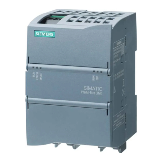
PN/M-Bus LINK is a communication gateway and enables the connection of SIMATIC controllers to the M-Bus fieldbus via PROFINET. It enables data and information exchange between PROFINET and M-Bus. Figure 3-1 SIMATIC PN/M-Bus LINK PN/M-Bus LINK Operating Instructions, 03/2018, A5E44260928-AA... -
Page 13: Features
System overview 3.2 Features Features General features ● 1 M-Bus connector (3-pin screw-type terminal). ● The device supports baud rates between 300 and 9600 baud. ● Communication with the individual slaves in the M-Bus network can be performed with different baud rates. ●... -
Page 14: System Configuration
System overview 3.3 System configuration System configuration System configuration The following figure shows a basic system configuration with PN/M-Bus LINK as a communication gateway between a PROFINET network and an M-Bus network. Figure 3-2 System configuration with PN/M-Bus LINK Purpose and function of the system components PN/M-Bus LINK enables the connection of the M-Bus to PROFINET. -
Page 15: System Requirements
System overview 3.4 System requirements System requirements System requirements ● PN/M-Bus LINK ● Controller: Supported are SIMATIC S7-1200, SIMATIC S7-1500, SIMATIC ET 200SP, SIMATIC OpenController ● 24 V power supply ● M-Bus network ● PROFINET bus ● Windows PC (for configuring, commissioning and diagnostics) ●... -
Page 16: Design
System overview 3.5 Design Design PN/M-BUS LINK setup The following figure shows the arrangement of the connection and display elements on PN/M-Bus LINK. The figure shows the device without a top and bottom enclosure cover. Design ① 24 V DC + functional grounding ②... -
Page 17: Functions
Functions Cyclic and acyclic data exchange PN/M-Bus LINK is always the M-Bus master. The functions of the PN/M-Bus LINK enable you to read measured data from connected M-Bus devices. To do this, the M-Bus functions "SND_NKE", "SND_UD" and "REQ_UD2" are implemented in PN/M-Bus LINK. It is not possible to configure or write to M-Bus devices. - Page 18 Functions 4.1 Cyclic and acyclic data exchange Cyclic data exchange: Control and status information The transmission of control and status information between the S7 controller and PN/M-Bus LINK is performed via the cyclic IO process image. In order to read measurement data from a specific M-Bus device, the S7 user program sets the control bit for the respective M-Bus slave in the cyclic output data from the value "0"...
- Page 19 Functions 4.1 Cyclic and acyclic data exchange Acyclic data exchange: Reading measurement data from M-Bus devices The measured values are transferred from the PN/M-Bus LINK to the S7 control system through data records. The PN/M-Bus LINK always reads all available measured values from an M-Bus device and saves the measured values as a data record.
-
Page 20: Response To Errors
Functions 4.2 Response to errors Response to errors Diagnostic resource The device provides various tools to isolate the cause. These tools are listed below: Diagnostic resource Description LED display PN/M-Bus LINK signals its status with the LEDs on the front of the enclo- sure. -
Page 21: Application Planning
Application planning Installation guidelines General installation guidelines Observe the following guidelines when mounting and connecting PN/M-Bus LINK: ● When connecting PN/M-Bus LINK, ensure that you comply with all applicable and binding standards. Adhere to the relevant national and regional regulations when installing and operating the device. -
Page 22: Installation Location
Application planning 5.2 Installation location Installation location Selection of the installation site / installation You can mount PN/M-Bus LINK either on a control panel or on a standard mounting rail: Installation in control cabinet / device connection box NOTICE The device is intended for installation in a control cabinet or in a device connection box. It is important to note that installation in a control cabinet or device connection box is essential for compliance with the UL regulations. - Page 23 Application planning 5.2 Installation location Permitted mounting positions and permitted ambient temperature The table below show the permitted temperature range for the different mounting positions. Mounting position Permitted ambient temperature Horizontal -25 ... +60 °C Vertical -25 ... +55 °C Lying -25 ...
- Page 24 Application planning 5.2 Installation location Minimum spacing PN/M-Bus LINK is designed for natural heat dissipation by convection. Therefore observe sufficient clearances: ● For horizontal mounting position: At least 35 mm above and below PN/M-Bus LINK ● For vertical mounting position: At least 35 mm left and right of PN/M-Bus LINK Provide sufficient space for the connection of supply voltage, Ethernet and M-Bus.
-
Page 25: Transportation
Application planning 5.3 Transportation Electromagnetic compatibility (EMC) / overvoltage protection NOTICE Damage to the device Inadequately dimensioned overvoltage protection can result in severe damage to the device. Always ensure, therefore, that the overvoltage protection is adequate (see Chapter Connecting 24 V DC (Page 31)). Transportation The devices must be transported in a clean and dry state, preferably in their original packaging. -
Page 26: Mounting/Extending
Mounting/Extending Installing the device PN/M-Bus LINK can be mounted on a 35 mm standard mounting rail according to DIN EN 60715 or on a control panel. Information on the selection of the location of use as well as reliable mounting positions and minimum clearances is available in the section Installation location (Page 20). - Page 27 Mounting/Extending 6.1 Installing the device Mounting to a control panel Preparations ● Drill holes (M4). The dimensions for the drill holes are available in the figure below. Mounting Proceed as follows: ① 1. Move the sliders to the outside until they latch in place. 2.
-
Page 28: Connecting
Connecting Safety instructions and guidelines Safety information WARNING Connection only over safety extra-low voltage / protective extra-low voltage May cause death or serious injury The device is designed for operation using directly connectable safety extra-low voltage (SELV) with safe electrical separation according to IEC 60950-1 / EN 60950-1 / VDE 0805-1 or IEC 61131-2 / EN 61131-2 / DIN EN 61131-2. - Page 29 Connecting 7.1 Safety instructions and guidelines Wiring guidelines When wiring the PN/M-Bus LINK, follow the wiring guidelines of your automation system (e.g. SIMATIC S7-1200, SIMATIC S7-1500, SIMATIC ET 200SP). Also observe the installation instructions and configuration guidelines for routing of the PROFINET cables.
-
Page 30: Power Supply And Potential Ratios
Connecting 7.2 Power supply and potential ratios Power supply and potential ratios Block diagram Alternative connection option for M-Bus cable shield: ① Connection of the shield to M-Bus screw-type terminal ② Connection of the shield to the shield busbar Figure 7-1 Block diagram Current consumption at the 24 V DC connection The supply voltage for the M-Bus network is generated from the supply voltage at the... - Page 31 Connecting 7.2 Power supply and potential ratios Example 2: Maximum current consumption ● Load on M-Bus: 40 standard loads (40 x 1.5 mA) + 1 x short circuit (100 mA) ● Supply voltage: +20.4 V ● M-Bus voltage: +32.4 V ●...
- Page 32 Connecting 7.2 Power supply and potential ratios Shielding PROFINET interface The shields of the PROFINET interface are galvanically connected. Always apply the shields of the PROFINET Ethernet cable at both ends. M-Bus interface You can use either shielded or unshielded M-Bus cables in the M-Bus network. However, we do recommend the use of shielded M-Bus cables.
-
Page 33: Connecting 24 V Dc
Connecting 7.3 Connecting 24 V DC Connecting 24 V DC 24 V DC power supply 24 V DC connection The connection of the external 24 V power supply and of the ① functional earth is made over a 3-pin screw terminal . -
Page 34: Connecting The Functional Ground
Connecting 7.4 Connecting the functional ground Connector pin assignment The figure below shows the assignment of the terminal for the 24 V DC power supply. Table 7- 1 Terminal assignment for the 24 DC power supply 24 V supply for PN/M-Bus LINK (+) 24 V supply for PN/M-Bus LINK (-) Functional ground Permissible torques for screw terminal:... -
Page 35: Connecting Profinet
Ethernet connections are attached to the lower part of the PN/M-Bus LINK enclosure in the factory state. These retaining collars are intended for the Siemens FastConnect connectors. NOTICE Make sure you observe the minimum bending radius of the Ethernet cable; otherwise the shield effect of the cable shield may be impaired. -
Page 36: Connecting The M-Bus
Connecting 7.6 Connecting the M-Bus Connecting the M-Bus Connecting the M-Bus The PN/M-Bus LINK is connected to the M-Bus via a two- ① wire cable to the M-Bus connection Conductor cross-section: max. 1.5 mm Suitable cables: Twisted two-wire line YCYM or J-Y(ST)Y 2 x 2 x 0.8 mm. -
Page 37: Commissioning
Commissioning Commissioning PN/M-Bus LINK Requirements ● The PN/M-Bus LINK is mounted and connected to a SIMATIC S7 CPU via PROFINET. ● The M-Bus is connected to the PN/M-Bus LINK ● PN/M-Bus LINK and all other components are wired and connected. Basic commissioning procedure After commissioning of the hardware perform the additional steps required for commissioning in the TIA Portal. -
Page 38: Configuring / Programming
Otherwise, you must integrate the PN/M-Bus LINK by installing a GSDML file. The GSDML file "GSDML-V2.32-Siemens-PN_MBUS_LINK-yyyymmdd.xml" is available for the TIA Portal V15. If needed, you can contact your Siemens contact person (mailto:customized.automation@siemens.com) to request the GSDML file. The GSDML file is installed in the TIA Portal via "Options >... - Page 39 Configuring / Programming 9.2 TIA Portal Devices & Networks TIA Portal: Devices & networks Follow these steps: ① 1. Select the PN/M-Bus LINK with its specific article number from the hardware catalog PN/M-Bus LINK appears in the "Devices & networks"window. 2.
-
Page 40: Inserting And Configuring M-Bus Devices
Configuring / Programming 9.3 Inserting and configuring M-Bus devices Inserting and configuring M-Bus devices PN/M-Bus LINK is already entered as an M-Bus master in slot 1. You create M-Bus devices manually by inserting a generic M-Bus device from the hardware catalog. Inserting an M-Bus device ①... - Page 41 Configuring / Programming 9.3 Inserting and configuring M-Bus devices Creating additional M-Bus devices You can create additional M-Bus devices as required. Note You can place a maximum of 40 M-Bus device modules from the hardware catalog. Empty slots between filled slots are not used for communication but still count. Module failure The setting of the input values in case of a module failure is a fixed value that cannot be changed.
-
Page 42: Checking And Compiling The Configuration
Configuring / Programming 9.4 Checking and compiling the configuration Checking and compiling the configuration Checking / adapting I/O addresses If necessary, you must adapt the I/O addresses assigned automatically by the TIA Portal. This is possible, for example, in the "Device overview" window. Here you can also find the I/O addresses used by the slots. -
Page 43: Diagnostics
Diagnostics 10.1 Status LEDs 10.1.1 Operating state of the PN/M-Bus LINK / PROFINET diagnostics The LEDs for visualizing the operating states of PN/M-Bus LINK and the PROFINET ports are located on the front of the enclosure. Figure 10-1 Status LEDs - Operating state of PN/M-Bus LINK / PROFINET diagnostics PN/M-Bus LINK Operating Instructions, 03/2018, A5E44260928-AA... - Page 44 Diagnostics 10.1 Status LEDs ERROR MAINT Operating Description state Power-up test / For approximately 1 second: LED test • Serious error during startup Longer than 1 second: HW error detected • during power-up test or other serious error System run-up System not completely booted yet but •...
-
Page 45: Connection Status Of The M-Bus
Diagnostics 10.1 Status LEDs 10.1.2 Connection status of the M-Bus Connection status of the M-Bus PN/M-Bus LINK signals its status with the M-Bus LEDs on the front of the enclosure. Figure 10-2 Status LEDs M-Bus Table 10- 1 Behavior of the RUN LED RUN LED Meaning Note... -
Page 46: Connection Status Of Ethernet Interfaces
Diagnostics 10.1 Status LEDs 10.1.3 Connection status of Ethernet interfaces The LEDs for indicating the connection status of the Ethernet interfaces are located under a housing flap. Figure 10-3 Status LEDs, Ethernet interfaces LINK Indicates whether there is a physical connection on the Ethernet level. Connection exists No connection exists Rx/Tx... -
Page 47: Diagnostic Messages To The S7 Controller
Diagnostics 10.2 Diagnostic messages to the S7 controller 10.2 Diagnostic messages to the S7 controller 10.2.1 Events that trigger a diagnostic message Diagnostics The table below provides you with the following information: ● Message text assigned to diagnostic ● Event for triggering the diagnostics ●... -
Page 48: Status Byte In Cyclic Io Image
Diagnostics 10.2 Diagnostic messages to the S7 controller 10.2.2 Status byte in cyclic IO image The cyclic IO image contains a status byte that informs when an error has occurred when reading from an M-Bus device. The status byte only contains the information that an error has occurred. Detailed information about the error that has occurred is contained in the corresponding data record. -
Page 49: Maintenance And Service
Maintenance and service 11.1 Firmware update Procedure Follow these steps: 1. Set the S7 CPU to STOP mode. 2. Trigger the update of PN/M-Bus LINK in the TIA Portal. Depending on the configuration in the TIA Portal, PN/M-Bus LINK starts again automatically after a successful update and waits for the configuration information from the S7 controller. -
Page 50: Replacing Pn/M-Bus Link
Maintenance and service 11.3 Replacing PN/M-Bus LINK 11.3 Replacing PN/M-Bus LINK The basic steps for replacing the PN/M-Bus LINK are described below. Preparations Disconnect the S7 setup including PN/M-Bus LINK from the power supply. Replacing the device Follow these steps: 1. -
Page 51: Recycling And Disposal
There is no provision for returning the device to Siemens. For further questions regarding disposal and recycling, please contact your local Siemens contact. You will find the contact details in our database on the Internet at: http://www.automation.siemens.com/partner... -
Page 52: Technical Specifications
Technical specifications 12.1 Technical specifications PN/M-Bus LINK Article number 6BK1622-0AA00-0AA0 General information Product type designation PN/M-Bus LINK Firmware version FW update possible • Product function I&M data • Engineering with STEP 7 V15 or higher STEP 7 TIA Portal configurable/integrated •... - Page 53 Technical specifications 12.1 Technical specifications Article number 6BK1622-0AA00-0AA0 Interfaces PROFINET IO automatic detection of transmission rate • 100 Mbit/s Transmission rate, max. • Number of RJ45 ports • Number of FC (FastConnect) connections • PROFINET functions Assignment of the IP address, supported •...
- Page 54 Technical specifications 12.1 Technical specifications Article number 6BK1622-0AA00-0AA0 Interrupts/diagnostics/status information Status indicator Alarms Diagnostic functions Diagnostics indication LED RUN LED • ERROR LED • MAINT LED • LINK LED • RX/TX LED • Potential separation Potential separation exists Degree and class of protection Degree of protection acc.
-
Page 55: Dimension Drawing
Technical specifications 12.2 Dimension drawing 12.2 Dimension drawing Dimensional drawing of PN/M-Bus Link PN/M-Bus LINK Operating Instructions, 03/2018, A5E44260928-AA... -
Page 56: Appendix
You can check which of the following approvals have been granted for your product by the markings on the type plate. CE marking The SIMATIC PN/M-Bus LINK device fulfills the requirements and protection objectives of the following EC directives. EMC Directive 2014/30/EU The product is designed for use in the following areas: ●... -
Page 57: Contact Address
Licenses Use of open source software (OSS) The SIMATIC PN/M-Bus LINK product uses open source software in unchanged or a form we have modified. Licensing terms and sources that are to be published are included on the CD/DVD delivered with the product. -
Page 58: Service & Support
You can contact the Technical Support experts in Germany at the following number: ● Phone: + 49 (0) 911 895 7222 ● The contact data for Technical Support in other countries can be found in the Siemens contact database (http://w3.siemens.com/aspa_app/). -
Page 59: Glossary
Glossary AR (Application Relation) S7 connection for data exchange in PROFINET CI Field (Control Information Field) DIF (Data Information Field) FE (functional grounding) Low-impedance connection to ground potential GSDML (General Station Description Markup Language) GSDML is a language for describing PROFINET IO field devices. This language is used to create a GSD (General Station Description). - Page 60 Glossary SIMATIC Controller The SIMATIC Controllers are available as Basic, Advanced, Distributed and Software controllers. The Basic Controller S7-1200 for small to medium-sized applications, the Advanced Controller S7-1500 for medium-sized and complex applications, the Distributed Controller ET 200SP for distributed applications and the Software Controller S7-1500 for PC- based applications.
-
Page 61: Index
Index 24 V DC connection, 14 EMC interferences, 32 ERROR LED, 42 Ethernet cable, 33 Ethernet interface, 44 Acyclic communication, 12 FE terminal, 32 Firmware update, 47 Basic knowledge Functional ground, 32, 32 Documentation, 5 Gateway, 10, 12 Cable routing, 27 Grounding, 27 Cables Requirements, 27... - Page 62 Index Notes Wiring guidelines, 27 Installation, 20 Open-source software, 55 PN/M-Bus LINK Design, 14 Power supply, 12, 31 PROFINET, 11 Connecting, 33 Purpose Documentation, 5 Recycling, 49 Requirements Cables, 27 Retaining collar, 33 RUN LED, 42 Safety information General, 7 Working on the device, 8, 26 Scope of delivery, 23 Shielding, 30...
Need help?
Do you have a question about the SIMATIC PN/M-Bus LINK and is the answer not in the manual?
Questions and answers