Titan TTK587GD0 Safety And Operating Manual

Titan TTK587GD0 Safety And Operating Manual

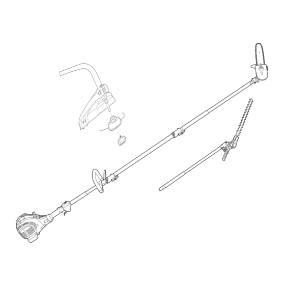
25cc petrol multi tool advanced

Advertisement

Advertisement

Table of Contents
loading

Summary of Contents for Titan TTK587GD0

  • Page 2: Your Product

    YOUR PRODUCT A. Main Unit A1. Air vents A12. Clamp A2. Spark plug connector A13. Locking pin A3. Choke lever A14. Locking knob A4. Primer A15. Auxiliary handle A5. Air filter case A16. Control unit A6. Fuel tank cap A17. Handle grip A7.
  • Page 3 D. Pruner attachment D1. Chain oil tank cap D9. Clutch D2. Cover D10. Drive sprocket D3. Locking nut D11. Tension pin D4. Spring washer D12. Tension screw D5. Pivot D13. Bolt D6. Saw chain D14. Oiling port D7. Guide bar D15.
  • Page 4 E. Tools Multi tool I: Cross-head screw driver / E5. Hex key 4 mm socket wrench rod(used with Multi tool II) Multi tool II: Spark plug wrench / socket E6. Multi tool IV: Socket wrench / wrench(used with Multi tool I) slotted screw driver Multi tool III: Torx screw driver / spindle E7.
  • Page 5 PRUNER Chain oil tank 150 ml Saw chain speed 21 m/s Max. cutting length 180 mm Guide bar length 203 mm Guide bar type 552912 Saw chain type 91PJ033X Chain pitch 9.525 mm (3/8”) Chain gauge (thickness of drive links) 1.27 mm (0.050”) Drive sprocket (teeth and pitch) 6 teeth x 9.525 mm(3/8”)
  • Page 6: Assembling Instructions

    3. ASSEMBLING INSTRUCTIONS WARNING! Read all instructions carefully. Do not connect the spark plug before it is completely assembled. Always use glove s during assembly. INTENED USE 1. This 4 in 1 petrol multi-tool TTK587GDO is designated with an engine displacement of 25cm³.
  • Page 7 3. Place the handle (A15) onto the shaft from the top and secure it with the longer screws. Tighten them with the hex key (E5). (See Fig. 1) Fig. 1 Adjusting The Handle Adjust the position and angle of the auxiliary handle (A15) on the upper shaft. 1.
  • Page 8 WARNING! Always switch the product off and disconnect the spark plug connector before adjusting the saw chain tension! The cutting edges of the saw chain are sharp. Always wear protective gloves when handling the chain! Always maintain proper chain tension! A loose chain increases the risk of kickback! A loose chain may jump out of the guide bar groove! This may injure the operator and damage the chain! A loose chain will cause rapid wear to the chain, guide bar and sprocket!
  • Page 9: Chain Lubrication

    CHAIN LUBRICATION Filling Chain Oil WARNING! The product is not filled with chain oil. It is essential to fill the product with chain oil before using it! Never operate the product without chain oil as this will result in extensive damage to the product!! Operating the saw chain dry or with too little chain oil will decrease cutting efficiency, shorten the product life span and cause rapid wear to the saw chain and guide bar from overheating! Insufficient chain oil is evident by smoke or bar discoloration!
  • Page 10 1. Make sure the guide bar (D7) and the saw chain (D6) are in place when you check the oil delivery. 2. Start the engine; keep it running at medium power and check if the chain oil is delivered as shown in the figure.
  • Page 11: Fuel And Engine Oil

    4. OPERATING INSTRUCTIONS FUEL AND ENGINE OIL This product is equipped with a 2-stroke engine, the fuel and oil tank are combined and it is essential to fill a fuel-oil mixture before operating this product. Observe the technical specifications for suitable fuel and engine oil. WARNING! This product is not supplied with fuel-oil mixture in the engine! Before operating this product it is essential to fill it with fuel! WARNING! Fuel and oil are highly inflammable! Fumes will explode if lit! Ensure that...
  • Page 12: Starting Instructions

    NOTE: Fuel and oil deteriorate over time. It may be difficult to start the engine if you use fuel which has been kept for more than 30 days. Towards the end of the season, it is advisable to put only as much fuel in the tank as you need for each mowing of the lawn, since it should be completely used up before storing the product.
  • Page 13 WARNING! Make sure that the cutting blade is not touching the ground or other objects when starting the product! 5. Allow the product to run at idle speed for 10 to 15 seconds to let it warm up; move the choke lever (A3) to its "...
  • Page 14: Operation

    WARNING! Make sure that the cutting blade is not touching the ground or other objects when starting the product! OPERATION 1. Press the throttle interlock (A20), hold it in position and then press the throttle trigger (A18) to engage the attachment (Fig. 22). 2.
  • Page 15 Fig. 29d Pruner Angle adjustment Adjust the attachment angle continuously to fit the growth of the plant. 1. Press the locking lever (D8) downward and hold it in position. (See Fig. 30a) Fig. 30a 2. Adjust the pruner head to required position and then release the locking lever (D8). (See Fig.
  • Page 16 Kickback WARNING! Beware of kickback! Kickback can lead to dangerous loss of control of the product and result in serious or fatal injury to the operator or anyone standing close by! Always be alert because rotational kickback and pinch kickback are major product operational dangers and the leading cause of most accidents! 1.
  • Page 17 Fig. 31b 4. Never stand directly under the limb you are sawing. Objects may fall different than expected. Always position yourself out of the path of falling limps. (See Fig. 31c) 5. Keep other persons away from cutting end of product and at a safe distance from the work area.
  • Page 18 NOTE: The chain must be running at full speed before it comes into contact with the wood. Cutting Thin Branches Thin branches can be cut off with one single cut. To prevent the branch from slivering and buckling the branch should be cut off in several pieces. (See Fig. 32) Fig.
  • Page 19 WARNING! After changing the trimming line, run the product under no load for at least a minute to make sure that the line and the product are operating correctly! WARNING! Never use steel thread! Always use cutting means in perfect condition, free of damage! Blade (Hedge Trimmer) 1.
  • Page 20 5. Take off the guide bar and chain. (Fig.35d) Fig. 35d 6. Ensure that the tension pin (D11) is adjusted to its far right position before assembly the checked or the new chain and guide bar. If not, turn the tension screw (D12) anticlockwise with the slotted screwdriver (E6).
  • Page 21 10. Put it together with the spring washer (D4) and cover (D2),and tighten locking nut (D3) with the socket wrench (E6) clockwise . (See Fig. 34h, 34i) NOTE: The saw chain (D6) has not yet been tensioned. Tension the chain as described under “Saw chain tensioning”.
  • Page 22 Fig. 36b 5. Check the guide bar 'rail' for wear: Hold a ruler (straight edge) against the side of the guide bar and 'cutter side plates'. If there is a gap between the ruler and guide bar the guide bar 'rail' is normal. If there is no gap (ruler flush against the side of the guide bar) the guide bar 'rail' is worn and needs to be replaced with a new one of the same type.
  • Page 23 Fig. 37a 3. To sharpen the chain proceed as follows: - Use protective gloves. - Ensure the chain is correctly tensioned. - Engage the chain brake to lock the chain on the bar. 4. Use a suitable file, whose diameter is 1.1 times the cutting tooth depth. Make sure 20% of the file diameter is above the cutter's top plate.
  • Page 24: Air Filter

    Fig. 37c AIR FILTER 1. Inspect the air filter regularly. Replace it with a new one if necessary. 2. Open the air filter case (A5) with the cross-head screwdriver (E1, E2), and remove the filter. (See Fig. 38) Fig. 38 3.
  • Page 25: Bevel Gear

    Fig. 39a 4. Check the spark plug for damage and wear. The colour of the electrode should be light- brown coloured. 5. Remove debris from the electrode with a soft wired brush; avoid heavy cleaning of the electrode. 6. Dry the spark plug with a soft cloth if it is wet from fuel. 7.
  • Page 26: Environmental Protection

    STORAGE 1. Clean the product as described above. 2. Store the product and its accessories in a dry, frost-free, well-ventilated place. 3. Always store the product in a place that is inaccessible to children. The ideal storage temperature is between 10 and 30°C. 4.
  • Page 27: Troubleshooting

    6. Troubleshooting WARNING! Suspected malfunctions are often due to causes that the user can fix themselves. Therefore check the product using this section. In most cases the problem can be solved quickly. WARNING! Only perform the steps described within these instructions! All further inspection, maintenance and repair work must be performed by an authorised service centre or a similarly qualified specialist if you cannot solve the problem yourself!
  • Page 28 B. Grass trimmer Shaft Spindle Trimming guard Line cutter Trimmer head Trimming line Bumper 25CC PETROL MULTI TOOL TTL488GDO...
  • Page 29 C. Hedge trimmer attachment Hedging blade Blade protection sheath Bolts Unlock levers Locking pin Hedge trimmer shaft Gripping surface...
  • Page 30: Technical Data

    TECHNICAL DATA GENERAL Engine type Sl33, air cooled 2-stroke Engine displacement 25cc Max. engine power 0.8 kW Max. engine speed 10500 /min Engine idle speed 3000 /min Clutch engagement speed 4500 /min Fuel tank volume 500 ml Fuel type #95 unleaded, in a 40:1 ratio mix with 2 stroke oil Fuel consumption at maximum engine power 0.38 kg/h...
  • Page 31: Hedge Trimmer

    HEDGE TRIMMER Max. cutting length 390 mm Max. cutting capacity 24 mm No-load speed 2500/min Adjustable cutting angle range -90° --- +60° Noise values Sound pressure level L 77.7 dB(A) pA,ld Sound pressure level L 96.5 dB(A) pA,R Sound pressure level L 93.5 dB(A) pA,av Uncertainty...
  • Page 32 OPERATION INSTRUCTIONS WARNING! Read all instructions carefully. Do not connect the spark plug before it is completely assembled. Always use gloves during assembly. INTENED USE 1. This 2 in 1 petrol multi tool is designated with an engine displacement of 25CC. Depending on the attached accessory this product is intended to be used as: 1).
  • Page 33 ASSEMBLY INSTRUCTIONS WARNING! Be careful with small parts that are removed during assembly or when making adjustments. Make sure you do not lose them. 1. AUXILIARY HANDLER ASSEMBLY 1). Loosen the outer pre-assembled screws on the auxiliary handle (A14). NOTE: There are holes on the bottom side of the upper shaft above the clamp to adjust the position of the handle.
  • Page 34 2). Safety guard assembly Warning: Take great care when fitting the guard. The guard is fitted with a very sharp cutting edge. Please note for your safety the cutting edge is covered with a blade cover. a). Remove the bolt and screw nut on the guard (B3). b).Place the guard over the end of the spindle (B2) and align the holes in the front of the guard with the Fig.
  • Page 35 7. GRASS TRIMMER 1). Use the trimmer head (B5) to cut smaller types of weed, lawn grass or similar soft vegetation. 2). Remove the protection cap from the line cutter (B4). 3). Hold the product firmly so that it sits with a gap between the product and your right side.
  • Page 36 12). Pay special attention when performing the work close to trees and bushes. The cutting heads could damage sensitive bark, and damage fence posts. (See Fig. 15g) 8. HEDGE TRIMMER 1). Angle adjustment Adjust the attachment angle to fit the growth of the plant.
  • Page 37 d). Cut both sides from the bottom cutting upwards to the top. This will prevent any of the cuttings falling into the path of the area still to be cut. (See Fig. 17a) e). After cutting the sides proceed to the top. f).
  • Page 38: Maintenance

    MAINTENANCE WARNING! Always switch the product off, let the product cool down and disconnect the spark plug connector before performing inspection, maintenance and cleaning work! WARNING! Only perform repairs and maintenance work according to these instructions! All further works must be performed by a qualified specialist! WARNING! Wear safety gloves when working on the attachment heads and close to it! Use...
  • Page 39 6. To replace the trimming line, press the release latch of the trimmer head housing to open the cover. 7. Cut a new 6 m long trimming line with a diameter of 2 mm. Form a loop at the middle of the line and insert this loop into the hook on the spool.
  • Page 40 SPARK PLUG NOTE! This engine uses a CHAMPION RCJ6Y spark plug with 0.6-0.7mm electrode gaps. Use a suitable replacement and replace once a year. You can it replace with “CHAMPION” or “NGK” as an alternative. 1. Inspect the spark plug at least every 25 hours or prior to long-term storage over 30 days if the use has not been this high.
  • Page 41 TRANSPORTATION 1. Switch the product off and disconnect the spark plug connector before transporting it anywhere. 2. Attach transportation guards for cutting means of hedge trimmer. 3. Always carry the product by its handles. 4. Protect the product from any heavy impact or strong vibrations which may occur during transportation in vehicles.
  • Page 42 TROUBLESHOOTING WARNING! Suspected malfunctions are often due to causes that the user can fix themselves Therefore check the product using this section. In most cases the problem can be solved quickly. WARNING! Only perform the steps described within these instructions! All further inspection, maintenance and repair work must be performed by an authorised service centre or a similarly qualified specialist if you cannot solve the problem yourself! Problem...

This manual is also suitable for:

Ttk587gdo

Table of Contents