REMEHA Gas 210 ECO PRO Series Installation, User And Service Manual
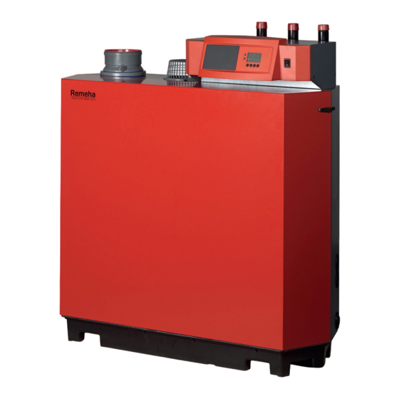
High-efficiency floor-standing gas boiler
Hide thumbs
Also See for Gas 210 ECO PRO Series:
- User manual (64 pages) ,
- Technical information (48 pages) ,
- Service manual (24 pages)

Related Manuals for REMEHA Gas 210 ECO PRO Series


Summary of Contents for REMEHA Gas 210 ECO PRO Series
- Page 1 United Kingdom Installation, User and Service Manual High-efficiency floor-standing gas boiler Gas 210 ECO PRO 210-80 – 210-120 – 210-160 – 210-200...
- Page 2 Dear Customer, Thank you very much for buying this appliance. Please read through the manual carefully before using the product, and keep it in a safe place for later reference. In order to ensure continued safe and efficient operation we recommend that the product is serviced regularly. Our service and customer service organisation can assist with this.
-
Page 3: Table Of Contents
Contents Contents Safety ................... . 6 General safety instructions . - Page 4 Contents 6.5.4 Connection options for the standard control PCB (PCU-01) ........36 6.5.5 Connection options for the 0–10 V PCB (IF-01) .
- Page 5 Contents 14.2 Optional electrical connections ..............69 14.2.1 Connection options for the control PCB (SCU-S01) .
-
Page 6: Safety
1 Safety Safety General safety instructions For the installer: Danger If you smell gas: 1. Do not use naked flames, do not smoke and do not operate electrical contacts or switches (doorbell, lighting, motor, lift etc). 2. Shut off the gas supply. 3. - Page 7 1 Safety Danger If you smell gas: 1. Do not use naked flames, do not smoke and do not operate electrical contacts or switches (doorbell, lighting, motor, lift etc). 2. Shut off the gas supply. 3. Open the windows. 4. Report any leaks immediately. 5.
-
Page 8: Recommendations
1 Safety Caution Ensure that the boiler is regularly serviced. Con tact a qualified installer or arrange a maintenance contract for the servicing of the boiler. Caution Only genuine spare parts may be used. Important Regularly check for the presence of water and pressure in the heating installation. - Page 9 Damaged or illegible instructions and warning stickers must be replaced immediately. Important Modifications to the boiler require the written ap proval of Remeha. 114494 - v.05 - 06022018...
-
Page 10: Specific Safety Instructions
1 Safety Specific safety instructions 1.3.1 Additional guidelines In addition to the legal requirements and guidelines, the supplementary guidelines in this manual must also be followed. Supplements or subsequent regulations and guidelines that are valid at the time of installation shall apply to all regulations and guidelines specified in this manual. -
Page 11: User's Liability
1 Safety 1.4.3 User's liability To guarantee optimum operation of the system, you must abide by the following instructions: Read and follow the instructions given in the manuals provided with the appliance. Call on a qualified professional to carry out installation and initial commissioning. -
Page 12: About This Manual
2 About this manual About this manual General This manual describes the installation, use and maintenance of the Gas 210 ECO PRO boiler. This manual is part of all the documentation sup plied with the boiler. Additional documentation The following documentation is available in addition to this manual: Installation and user manual for control panel Water quality instructions Symbols used in the manual... -
Page 13: Technical Specifications
3 Technical specifications Technical specifications Homologations 3.1.1 Certifications Tab.1 Certifications CE identification number PIN 0085BS0132 Class NOx Type of connection (1) EN 15502–1 3.1.2 Unit categories Tab.2 Unit categories Country Category Gas type Connection pressure (mbar) Great Britain G20 (H gas) 2H3P G31 (propane) 37-50... - Page 14 3 Technical specifications Gas 210 ECO PRO 210-80 210-120 210-160 210-200 Full load central heating efficiency (Hi) 97.43 97.5 97.54 97.6 80°C/60°C (92/42 EEC) Full load central heating efficiency (Hi) 104.3 104.7 105.2 105.7 50/30°C (EN15502) Central heating efficiency under low load 92.7 94.0 95.1...
- Page 15 3 Technical specifications Gas 210 ECO PRO 210-80 210-120 210-160 210-200 Fuse – main fuse 6.3 AT 6.3 AT 6.3 AT 6.3 AT Fuse – PCB 1.6 AT 1.6 AT 1.6 AT 1.6 AT Tab.7 Other data Gas 210 ECO PRO 210-80 210-120 210-160...
-
Page 16: Dimensions And Connections
3 Technical specifications Dimensions and connections Fig.1 Dimensions 1190 AD-0001419-01 Tab.9 Drawings Connection 210-80 210-120 210-160 210-200 1¼” male thread 1¼” male thread 1¼” male thread 1½” male thread Supply attach supplied 1¼” > 1½” adapter 1¼” male thread 1¼” male thread 1¼”... -
Page 17: Electrical Diagram
3 Technical specifications Electrical diagram Fig.2 Electrical diagram PCU-01 Pump Mains On / Off 1 2 3 1 2 3 4 1 2 3 1 2 3 4 1..6 4 6 7 10 SU-01 GN/YW PE-2 PE-6 PE-4 PE-5 PE-7 GN/YW GN/YW GN/YW... - Page 18 3 Technical specifications OR Orange Brown/White RD Red GN Green WH White Green/Yellow YW Yellow Yellow/White GY Grey 114494 - v.05 - 06022018...
-
Page 19: Description Of The Product
4 Description of the product Description of the product General description The Gas 210 ECO PRO is a free-standing gas boiler with the following characteristics: High-efficiency heating. Cast aluminium heat exchanger. Limited emissions of polluted substances. Has transport wheels as standard. The following boiler types are available: Gas 210 ECO PRO - 210-80 Gas 210 ECO PRO - 210-120... -
Page 20: Gas 210 Eco Pro Main Components
4 Description of the product Gas 210 ECO PRO main components Fig.3 Gas 210 ECO PRO AD-4000038-02 1 Flue gas outlet 16 Hydraulic pressure sensor 17 Gas multi-block measurement point 18 Venturi 3 Air box 19 Fan 4 Control panel 20 Mixing bend 5 Burner 21 Flue gas pressure switch... -
Page 21: Accessories And Options
4 Description of the product Accessories and options Various accessories can be obtained for the boiler. Important Contact us for more information. 114494 - v.05 - 06022018... -
Page 22: Before Installation
5 Before installation Before installation Installation regulations Warning The installer must be registered with Gas Safe and have the cor rect ACS qualifications. Important Practical guidelines - see the latest version. Choice of the location 5.2.1 Data plate Fig.4 Position of data plate The type plate is adhered above, against the casing on the right-hand side. -
Page 23: Location Of The Boiler
5 Before installation 5.2.2 Location of the boiler Fig.5 Clearance required 1490 2930 1190 1190 1190 2100 1890 1190 AD-4000036-02 The standard inspection and maintenance operations to the boiler are car ried out from the front. The inspection hatch on the heat exchanger is also located here. -
Page 24: Transport
5 Before installation Transport The boiler comes completely assembled and is delivered in packaging on a pallet, dimensions 700 mm x 1300 mm and 1450 mm high. Without the packaging, the boiler will fit through all standard doorways. Thanks to the specific compartments in the underframe, it is easy to move the boiler using a pallet truck or forklift truck. -
Page 25: Installation
6 Installation Installation General Warning The boiler must be installed by a qualified installer in accordance with local and national regulations. Hydraulic connections 6.2.1 Rinsing the system The installation must be cleaned and flushed in accordance with BS 7593 (2006) and BSRIA BG 33/2014. Before a new boiler can be connected to an existing or new system, the entire system must be thoroughly cleaned and flushed. -
Page 26: Connecting The Condensate Discharge Pipe
6 Installation Caution If using plastic pipes, follow the manufacturer's (connection) in structions. 6.2.3 Connecting the condensate discharge pipe Fig.7 Connecting the condensate drain 1. Fit a plastic drain pipe of Ø 32 mm or larger to the condensate drain, terminating in the drain. Caution Use only plastic material for the discharge pipe due to the acidi... -
Page 27: Air Supply/Flue Gas Connections
Outside wall terminal and con nection material: Discharge in the outside wall. Inlet opening for the air supply is in the same Remeha, combined with con pressure zone as the discharge (e.g. a com nection material from Muelink bined outside wall feed-through). -
Page 28: Requirements For Shaft For C
6 Installation Type Principle Description Permitted manufacturers This type of unit is supplied by the manufacturer When selecting the material, without a supply and discharge system. please note the following: Condensed water must flow back to the appliance The material must be resist ant to the flue gas tempera... -
Page 29: Material
6 Installation Fig.9 Minimum dimensions of shaft or Important duct The shaft must comply with the air density requirements of the lo cal regulations. Important Ø Always clean shafts thoroughly when using lining pipes and/or an air supply connection. It must be possible to inspect the lining duct. □... -
Page 30: Dimensions Of Flue Gas Outlet Pipe
6 Installation 6.4.4 Dimensions of flue gas outlet pipe Warning The pipes connected to the flue gas adapter must satisfy the fol lowing dimension requirements. Fig.11 Dimensions of open connection External dimensions of flue gas outlet pipe Tab.13 Dimensions of pipe (min-max) 150 mm 149 - 151 mm... - Page 31 6 Installation Caution The air supply opening must stay open. The installation area must be equipped with the necessary air supply openings. These openings must not be obstructed or shut off. If the boiler, in room-ventilated operation, has been set up in a (very) dusty room, use the air supply filter (accessory).
- Page 32 6 Installation Fig.14 Room-sealed version L Combined length of the flue gas outlet and air supply channel to the roof feed-through Flue gas outlet AD-4000100-01 Tab.16 Maximum chimney length for room-sealed operation Maximum length L Pipeline diameter 100 mm 130 mm 130 mm 150 mm 180 mm...
-
Page 33: Additional Guidelines
6 Installation Reduction table Tab.18 Pipe reduction for each element used Pipe reduction (in metres) Diameter 45° bend 90° bend 100 mm 110 mm 130 mm 150 mm 180 mm 6.4.6 Additional guidelines Installation For installing the flue gas outlet and air supply materials, refer to the in structions of the manufacturer of the relevant material. -
Page 34: Connecting The Air Supply
6 Installation Caution The pipes must be flue gas-tight and corrosion-resistant. The materials used must comply with the prevailing regulations and standards. The flue gas outlet pipe must be smooth and deburred. Connect the pipes so that they are stress-free. The pipes must not rest on the boiler or flue gas adapter. -
Page 35: Accessing The Terminal Connectors And Control Pcbs
6 Installation Maximum recorded 300 VA. power of external pump Recorded power in: Standby Part load Full load 210-80 36 W 125 W 210-120 37 W 193 W 210-160 53 W 206 W 210-200 54 W 317 W 6.5.3 Accessing the terminal connectors and control PCBs Fig.16 Standard control PCB (PCU-01) The control panel casing contains the standard control PCBPCU-01, the... -
Page 36: Connection Options For The Standard Control Pcb (Pcu-01)
6 Installation 6.5.4 Connection options for the standard control PCB (PCU-01) Fig.17 Standard control PCB (PCU-01) Various thermostats and regulators can be connected to the standard con trol PCB (PCU-01), as well as the circulation pump or a PC. F1 1.6 AT PCU-01 AD-4100111-01 On/off regulator (OT) -
Page 37: Connection Options For The 0-10 V Pcb (If-01)
6 Installation Release input Fig.21 Release input The boiler also comes with a release input that can be used to release/ block the burner. This input can be used in conjunction with flue gas valve end switches, hydraulic shut-off valves etc., for example. This input can be found on the RL terminals on the terminal block X6. - Page 38 6 Installation Caution Do not connect a frost thermostat or room thermostat to the boiler if using the 0–10 V PCB. Connecting the status relay (Nc) If the boiler locks out, a relay is de-energised and the alarm can be trans mitted via a potential-free contact (maximum 230 V, 1 A) on terminals Nc and C of the connector.
-
Page 39: Connection Options For The Pcb (Scu-X01)
6 Installation Analogue output (0–10 V) Fig.26 Switch jumper (1) This feedback can be based on temperature or heat output. The two con trols are described briefly below. A jumper (1) on the interface is used to select either temperature ( ) or out put (%). -
Page 40: Filling The Siphon
6 Installation The quality of the CH water must comply with certain limit values, which can be found in the Water quality instructions. The regulations and guide lines in this manual must be observed at all times. 6.6.2 Filling the siphon 1. -
Page 41: Commissioning
7 Commissioning Commissioning Checklist before commissioning 7.1.1 Preparing the boiler for commissioning Procedure to prepare the boiler for commissioning 1. Check the gas circuit. 2. Check the hydraulic circuit. 3. Check the water pressure in the central heating system. 4. Check the electrical connections of the thermostat and the other ex ternal connections. -
Page 42: Gas Settings
7 Commissioning The meaning of the error codes can be found in the error table. Gas settings 7.3.1 Adaptation to a different gas type Warning Only a qualified installer may carry out the following operations. Tab.24 Factory setting G20 (H gas) Parameter Description 210-80... - Page 43 7 Commissioning Setting full load Fig.29 Setting full load 1. Press the key. symbol will appear in the display. 2. Wait a while until appears in the display. Full load has now been set. AD-4000053-01 Checking/setting values O at full load 1.
- Page 44 7 Commissioning Setting low load Fig.31 Setting low load 1. Press the key. symbol will appear in the display. 2. Wait a while until appears in the display. 3. Press the key until appears on the display. Low load has now been set. AD-4000054-01 Checking/setting values for O at part load...
-
Page 45: Final Instructions
7 Commissioning Fig.32 Adjusting screw 5. Using the adjusting screw, set the percentage of O for the gas type being used to the nominal value. This should always be inside the highest and lowest setting limit. The direction in which the ad justment screw must be turned to increase or decrease the gas flow is indicated on the gas valve unit. -
Page 46: Operation
8 Operation Operation Use of the control panel The display on the control panel provides information about the operating status of the boiler and any errors. The manual for the control panel provides information on altering and reading out parameters, the meaning of fault codes and the deletion of the fault memory. -
Page 47: Settings
9 Settings Settings Description of Gas 210 ECO PRO parameters Tab.30 Factory setting for user level parameters Parame Description Adjustment range 210-80 210-120 210-160 210-200 Flow temperature: T 20 to 90ºC 0 to 98 minutes Post-circulation of the pump 99 minutes = continuous 0 = CH off Boiler control 1 = CH on... -
Page 48: Changing The Parameters
9 Settings Parame Description Adjustment range 210-80 210-120 210-160 210-200 0 = no waiting time Operating time of hydraulic flap 1-255 seconds (only if connec (optional) ted) 0 = no waiting time Operating time of flue gas valve 1-255 seconds (only if connec (optional) ted) 0 = no waiting time... -
Page 49: Setting The Parameters In The Installer Level
9 Settings Caution Modification of the factory settings may impair boiler operation. 9.2.1 Setting the parameters in the Installer level Fig.34 Access to the installer level Parameters at installer level (see table of parameters) may be modified only by a recognised installer. To prevent unwanted modifications to set tings, some parameters can only be changed after the special access code is entered. -
Page 50: Status And Sub-Status
9 Settings 9.3.2 Status and sub-status The information menu gives the following status and sub-status num bers: Tab.32 Status and sub-status numbers Status Sub-status Stand-by mode Stand-by mode Boiler start (heat demand) Anti-swing Open hydraulic valve Start pump Wait for the correct temperature before burner start Burner start Open external gas valve Fan on... - Page 51 9 Settings Status Sub-status Boiler stop (end of heat demand) Pump post circulation Pump off Close hydraulic valve Start anti-swing Control stop Wait for burner start Anti-swing Blocking Blocking code 114494 - v.05 - 06022018...
-
Page 52: 10 Maintenance
10 Maintenance 10 Maintenance 10.1 General The boiler does not require a lot of maintenance. Nevertheless, the boil er must be inspected and maintained periodically. Sweep the chimney at least once a year or more often, depending on the country's applicable regulations. Always check the combustion when the chimney is swept. -
Page 53: Checking The Combustion
10 Maintenance 10.2.5 Checking the combustion Combustion is checked by measuring the O percentage in the flue gas outlet duct. 10.2.6 Cleaning the siphon 1. Remove the siphon from the boiler and clean it. 2. Fill the siphon with clean water and attach the siphon. Danger The siphon must always be sufficiently filled with water. -
Page 54: Cleaning The Fan
10 Maintenance 10.3.1 Cleaning the fan Fig.35 Clean the 210-80 and 210-120 fan Operation of 210-80 and 210-120: 1. Remove the electrical connections from the fan. 2. Unscrew the union nut underneath the gas multi-block (watch out for the packaging). 3. - Page 55 10 Maintenance Fig.36 Clean the 210-160 and 210-200 fan Operation of 210-160 and 210-200: 1. Remove the electrical connections from the fan. 2. Remove the bolts attaching the venturi to the fan. 3. Remove the bolts and screws on the outlet side of the fan. 4.
-
Page 56: Clean Heat Exchanger
10 Maintenance 10.3.2 Clean heat exchanger Fig.37 Clean the heat exchanger 1. Unscrew the nuts from the inspection hatch on the heat exchanger. 2. Remove the inspection hatch from the heat exchanger. 3. Clean spaces between pins on the heat exchanger using the special cleaning tool/cleaning knife or compressed air. -
Page 57: Cleaning The Burner
10 Maintenance 10.3.3 Cleaning the burner Fig.38 Cleaning the burner 1. Lift the burner out of the heat exchanger. 2. Check the burner and, if necessary, clean without touching it (e.g. with compressed air between 2 and 5 bars: maintain a minimum dis tance of 1 cm from the surface of the burner). -
Page 58: Reassembling The Boiler
10 Maintenance 10.3.5 Reassembling the boiler 1. Fit all removed parts in the reverse order. Caution During inspection and maintenance operations, always replace all gaskets on the parts removed. 2. Carefully open the water tap. 3. Fill the installation with water. 4. -
Page 59: 11 Troubleshooting
Important Note the error code displayed. The error code is needed to find the cause of the error quickly and correctly and for any support from Remeha. 11.1.1 Blocking A (temporary) blocking mode is a boiler status, resulting from an abnormal state. - Page 60 11 Troubleshooting Blocking code Description Maximum difference between the flow and return temperature exceeded: No flow or insufficient flow: Check the circulation (direction, pump, valves) Check the water pressure Check the cleanliness of the heat exchanger Sensor error: Check that the sensors are operating correctly Check that the sensor has been fitted properly No release signal: External cause: remove external cause...
-
Page 61: Lock Out
Important The error code is needed to find the cause of the error quickly and correctly and for any support from Remeha. Press the key for two seconds. If the error code continues to display, search for the cause in the error table and apply the solution. - Page 62 11 Troubleshooting Error code Description Flow temperature sensor short circuited: Bad connection: check the wiring Sensor not connected or incorrectly connected: Check that the sensor has been fitted properly Check that the sensors are operating correctly Faulty sensor: replace the sensor if necessary Flow temperature sensor open: Bad connection: check the wiring Sensor not connected or incorrectly connected:...
- Page 63 11 Troubleshooting Error code Description Return temperature too low: Bad connection: check the wiring Faulty sensor: replace the sensor if necessary Sensor not connected or incorrectly connected: Check that the sensors are operating correctly Check that the sensor has been fitted properly No circulation: Vent the air from the CH system Check the circulation (direction, pump, valves)
- Page 64 11 Troubleshooting Error code Description Five failed burner starts: No ignition spark: Check cabling of ignition transformer Check the ionisation/ignition electrode Check breakdown to earth Check the condition of the burner cover Check the earthing Defective control SU PCB Ignition spark but no flame: Vent the gas supply to remove air Check that the gas valve is fully opened Check the gas supply pressure...
-
Page 65: Blockage And Fault Memory
11 Troubleshooting Error code Description 5x flame loss: No ionisation current: Vent the gas supply to remove air Check that the gas valve is fully opened Check the gas supply pressure Check the operation and setting of the gas valve unit Check that the air supply inlet and flue gas outlet are not blocked Check that there is no recirculation of flue gases Error in communication with SU PCB:... -
Page 66: 12 Disposal
12 Disposal 12 Disposal 12.1 Removal/recycling Important Removal and disposal of the boiler must be carried out by a quali fied person in accordance with local and national regulations. To remove the boiler, proceed as follows: 1. Switch off the boiler's electrical connection. 2. -
Page 67: 13 Spare Parts
Only replace defective or worn boiler parts with original parts or recom mended parts. Send the part to be replaced to the Remeha Quality Control department if the relevant part is covered by the guarantee (see the General Terms of Sale and Delivery). -
Page 68: Parts
13 Spare parts 13.2 Parts Fig.40 Gas 210 Eco Pro 210-80 210-160 210-120 210-200 210-200 210-80 210-120 210-160 210-200 210-200 210-80 210-120 210-160 210-200 AD-0801233-01 114494 - v.05 - 06022018... -
Page 69: 14 Appendix
14 Appendix 14 Appendix 14.1 ErP information 14.1.1 Product card Tab.35 Product card Remeha - Gas 210 ECO PRO 210-80 210-120 210-160 210-200 Seasonal space heating energy efficiency class Rated heat output (Prated or Psup) Seasonal space heating energy efficiency... - Page 70 14 Appendix 114494 - v.05 - 06022018...
- Page 71 © Copyright All technical and technological information contained in these technical instructions, as well as any drawings and technical de scriptions supplied, remain our property and shall not be multiplied without our prior consent in writing. Subject to alterations.
- Page 72 T +44 (0)118 978 3434 F +44 (0)118 978 6977 E boilers@remeha.co.uk Remeha Commercial UK Innovations House 3 Oaklands Business Centre Oaklands Park RG41 2FD Wokingham 114494 - v.05 - 06022018 114494...
Need help?
Do you have a question about the Gas 210 ECO PRO Series and is the answer not in the manual?
Questions and answers