
Subscribe to Our Youtube Channel
Related Manuals for REMEHA Gas 550


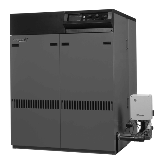
Summary of Contents for REMEHA Gas 550
- Page 1 Technical information Remeha Gas 550/550 Duo • Atmospheric gas boiler • 278 - 1058 kW Supplied By www.heating spares.co Tel. 0161 620 6677...
-
Page 2: Table Of Contents
9.3 Control panel 3 dimensions and Technical data 9.4 Electrical connections 3.1 Dimensions Remeha Gas 550 9.5 Electrical information 3.2 Dimensions Remeha Gas 550 Duo 9.6 Water level control 9.7 Wiring diagrams 4 Application information 4.1 L.P.H.W. system 10 Commissioning 4.1.1 Water temperature... -
Page 3: Preface
If you have any questions, or if you need more informa- tant information for the correct operation and maintenan- tion about specific subjects relating to this boiler, or it’s ce of the Remeha boiler, model Gas 550 and Gas 550 installation please do not hesitate to contact us. Duo. -
Page 4: Dimensions And Technical Data
Remeha Gas 550/550 Duo DIMENSIONS AND TECHNICAL DATA 3.1 Dimensions Remeha Gas 550 Fig. 01 Dimensions Remeha Gas 550 00.05F.79.00002 Flow Ø107 int. Return Ø107 int. Gas 2" Flue gas Ø Supplied By www.heating spares.co Tel. 0161 620 6677... - Page 5 1450 1695 1940 2185 2430 2675 2920 Flue gas flow rate kg/h 1033 1239 1376 1560 1678 Table 01 Technical data Remeha Gas 550 * Supplied with a flue gas pipe adapter Supplied By www.heating spares.co Tel. 0161 620 6677...
-
Page 6: Dimensions Remeha Gas 550 Duo
Remeha Gas 550/550 Duo 3.2 Dimensions Remeha Gas 550 Duo Fig. 02 Dimensions Remeha Gas 550 Duo 00.05F.79.00003 Flow Ø107 int. Return Ø107 int. Gas 2" Flue gas Ø Supplied By www.heating spares.co Tel. 0161 620 6677... -
Page 7: Application Information
1385 1694 2066 2478 2752 Table 02 Technical data Remeha Gas 550 Duo * Supplied with a flue gas pipe adapter APPLICATION INFORMATION 4.1 L.P.H.W. system specific minimum water flow requirements exist other 4.1.1 Water temperature then for overheating protection. -
Page 8: Noise Level
Under no circumstances is the boiler to be operated with cleaning chemicals in the system. Important: The Remeha Gas 550/550 Duo is a certified appliance To Summarise: and must not be modified or installed in any way con- - Minimise water loss;... -
Page 9: Typical Boiler Installations
Size B 1240 1460 1680 1900 2120 2340 2560 Size E 1295 1295 1295 1295 1295 1295 1245 Size H 1730 1730 1730 1610 1730 1610 1730 Fig. 03 Remeha Gas 550 00.05F.79.00004 Supplied By www.heating spares.co Tel. 0161 620 6677... -
Page 10: Installation 2
Recommended layout for boiler installation, measure- ments in mm. floor area number of sections size A size ØD number of sections Size A 1185 1405 1625 1845 Size Ø D Fig. 04 Remeha Gas 550 Duo 00.05F.79.00005 Supplied By www.heating spares.co Tel. 0161 620 6677... -
Page 11: Control And Safety Equipment
CONTROL AND SAFETY EQUIPMENT 6.1 General 6.3 Standard electronic gas train High/Low The Remeha Gas 550 is supplied with electronic control 6.3.1 Schematic and safety equipment with ionisation flame detection. 6.2 Instrument panel The Remeha Gas 550 is supplied with an instrument panel mounted in the front of the boiler, either left or right. -
Page 12: Specification Ignition Transformer
: ≤ 10 sec. Safety time problem has been rectified. Maximum ambient temperature : 60 °C Note: The Gas 550 Duo has two sets. Injector size pilot burner : Ø 1.0 mm Injector size main burner : Ø 5.4 mm 6.4.4 Valve leakage control - optional ( lock out) -
Page 13: Assembly And Installation Guidelines
Note: The Gas 550 Duo has two sets. The gas supply should be conforming to the British Gas safety regulations. Note: The Gas 550 Duo requires two gas supplies. Supplied By www.heating spares.co Tel. 0161 620 6677... -
Page 14: Electrical Supply
9.2 Instrument panel The Gas 550 is supplied with an instrument panel that Note: The Gas 550 Duo requires two sets of power supplies. is fitted in the front of the boiler, either left or right (dependant on flow and gas connection). -
Page 15: Wiring Diagrams
9.7 Wiring diagrams Fig. 08 Electrical principle diagram 04.05F.SC.00001 Supplied By www.heating spares.co Tel. 0161 620 6677... -
Page 16: Commissioning
Remeha Gas 550/550 Duo Fig. 09 Electric connection central alarm 00.03F.60.00042 COMMISSIONING Note: Commissioning must only be carried out by a 9. Switch on the boiler. qualified engineer with the relevant training and certifica- - If a valve leakage control is installed the following tion i.e. - Page 17 12. Set the correct full load burner pressure by means pressure switch HD. The boiler will resume opera- of the pressure regulator on the gas multibloc gas tion. • Set the correct full load burner pressure again valve(see Fig. 10, pos. 1). Warning: When the required burner pressure can according §10.2.12.
-
Page 18: Switching Off The Boiler
Remeha Gas 550/550 Duo 10.1 Switching off the boiler 1. Switch off the electric supply. 2. Shut off the gas cock. 1. pressure regulator Warning: When switched off and full of water the boiler 2. part load adjustment could be damaged if the temperature falls below freezing ring point. -
Page 19: Trouble Shooting
TROUBLE SHOOTING Fig. 11 Switch diagram Fig. 12 Switch diagram with valve leakage control (optio- nal) 04.05F.SC.00001 04.05F.SC.00001 12.1 Fault causes In case of all disturbances the gas supply is interrupted and the color disc stops rotating. Check the position of the color disc for a indication of the cause. - Page 20 Broag Ltd Head Office Remeha House, Molly Millars Lane, Wokingham, Berkshire RG41 2QP. Tel.: 0118 9783434 Fax: 0118 9786977 Email: boilers@broag-remeha.com Internet: www.broag-remeha.com Branch Office Unit 3, Kestrel Close, Quarry Hill Ind. Estate, Ilkeston, Derbyshire DE7 4RD © Copyright Tel. 0115 9440778...
Need help?
Do you have a question about the Gas 550 and is the answer not in the manual?
Questions and answers