Advertisement
Quick Links
Advertisement

Related Manuals for REMEHA GAS 310 ECO PRO


Summary of Contents for REMEHA GAS 310 ECO PRO
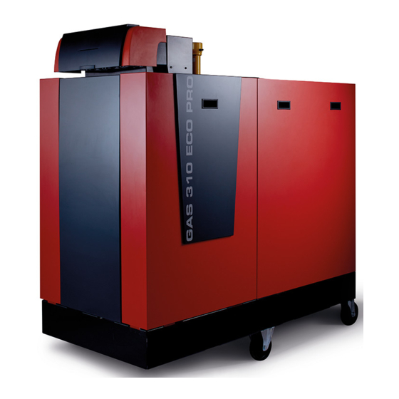
- Page 1 GAS 310/610 ECO PRO...
- Page 2 WHAT’S INSIDE 03 WELCOME TO REMEHA 23 ELECTRICAL CONNECTIONS AND CONTROLS 03 INTRODUCING THE REMEHA GAS 310/610 ECO PRO RANGE 24 WIRING LAYOUT 04 TYPICAL BOILER 25 SAFETY INTERLOCKS CONSTRUCTION 26 BOILER CONTROLS 07 OPERATING PRINCIPLE 28 FLUE DATA 08 TECHNICAL INFORMATION...
- Page 3 • 0-10V or volt free • Optional secondary return kit For use with both CT and VT circuits Quiet operation ≤68 dB(A) Improved comfort Left or right hand version Greater flexibility of (Gas 310 Eco Pro) plant room planning...
- Page 4 TYPICAL GAS 310 ECO PRO BOILER CONSTRUCTION Flow connection Air inlet Gas connection Air differential pressure switch Burner Gas pressure measurement point Flue gas discharge pipe Adapter Control panel Location for optional features Return connection Ignition/ionisation electrode or a control unit Outlet for measuring combustion gases Heat exchanger Gas pressure measurement point...
- Page 5 TYPICAL BOILER CONSTRUCTION TYPICAL GAS 610 ECO PRO BOILER CONSTRUCTION Flow connection Air inlet Gas connection Air differential pressure switch Burner Gas pressure measurement point Flue gas discharge pipe Adapter Control panel Location for optional features Return connection Ignition/ionisation electrode or a control unit Outlet for measuring combustion gases Heat exchanger...
- Page 7 OPERATING PRINCIPLE GAS 310/610 ECO PRO OPERATING PRINCIPLE Combustion air is drawn into the inlet connection from the plant room (conventionally flued) or from outside via the concentric flue system (room-sealed) by an air supply fan. On the inlet side of the fan is a specially designed chamber (Venturi unit) which takes gas from the multiblock and mixes it in the correct ratio with the incoming air.
- Page 8 GAS 310 ECO PRO TECHNICAL INFORMATION 285/5 335/6 430/7 500/8 575/9 650/10 PERFORMANCE Nominal heat output central heating 51-261 65-327 79-395 92-461 106-530 119-601 operation @ 80/60°C kW (min-max) Nominal heat output central heating operation @ 50/30°C kW (max) Nominal input (Hi) (min-max)
- Page 9 GAS 310 ECO PRO TECHNICAL INFORMATION GAS 310 ECO PRO TECHNICAL INFORMATION 285/5 335/6 430/7 500/8 575/9 650/10 HYDRAULICS Nominal flow rate @ 20°C ΔT l/s 3.12 3.91 4.72 5.51 6.34 7.19 Nominal flow rate @11°C ΔT l/s 5.68 7.11 8.59...
- Page 10 GAS 610 ECO PRO TECHNICAL INFORMATION 1000 1150 1500 (2 x 310/5) (2 x 310/6) (2 x 310/7) (2 x 310/8) (2 x 310/9) (2 x 310/10) PERFORMANCE Nominal heat output central heating 87-654 1060 1202 operation @ 80/60°C kW (min-max) Nominal heat output central heating 1148 1303...
- Page 11 GAS 610 ECO PRO TECHNICAL INFORMATION GAS 610 ECO PRO TECHNICAL INFORMATION 1000 1150 1500 (2 x 310/5) (2 x 310/6) (2 x 310/7) (2 x 310/8) (2 x 310/9) (2 x 310/10) HYDRAULICS Nominal flow rate @ 20°C ΔT l/s 3.12 (per module) 3.91 (per module) 4.72 (per module) 5.51 (per module) 6.34 (per module) 7.19 (per module) Nominal flow rate @11°C ΔT l/s 5.68 (per module) 7.11 (per module) 8.59 (per module) 10.03 (per module) 11.53 (per module) 13.07 (per module)
- Page 12 SUGGESTED ENGINEERING SPECIFICATION GAS 310 ECO PRO CONSTRUCTION CONTROLS The boiler will consist of a sectional cast aluminium heat The boiler will include a controls package that allows the actual exchanger with other major components contained within a and set values to be read and adjusted on the built-in digital...
- Page 13 SUGGESTED ENGINEERING SPECIFICATION GAS 610 ECO PRO before re-starting. The control cannot override the standard flame CONSTRUCTION safety controls. Standard frost protection shall activate below 7°C The boiler will consist of a sectional cast aluminium heat with stage one activating the system/shunt pump. Stage two shall exchanger with other major components contained within a activate below 3°C with the boiler switching on to 10°C flow.
- Page 14 GAS 310 ECO PRO DIMENSIONS BOILER Ø TYPE (MM) (MM) (MM) (MM) 310-285 (5) 1833 1635 1862 1490 310-355 (6) 1833 1635 1862 1490 310-430 (7) 1833 1635 1862 1490 Ø 310-500 (8) 2142 1944 2172 1800 310-575 (9) 2142 1944 2172 1800...
- Page 15 GAS 310 ECO PRO DIMENSIONS GAS 310 ECO PRO CONFIGURATION The service side with the inspection hatch on the heat exchanger is considered to be the front of the boiler. This boiler is available in both a left-hand and right-hand version.
- Page 16 GAS 610 ECO PRO DIMENSIONS BOILER TYPE (MM) (MM) (MM) (MM) 610-570 (5) 1833 1582 1862 1490 610-710 (6) 1833 1582 1862 1490 610-860 (7) 1833 1582 1862 1490 610-1000 (8) 2142 1892 2172 1800 610-1150 (9) 2142 1892 2172 1800 610-1300 (10) 2142 1982...
- Page 17 GAS 610 ECO PRO DIMENSIONS GAS 610 ECO PRO CONFIGURATION The Gas 610 Eco Pro boiler is not available with a choice between left or right hand versions, but the control panel can easily be rotated to enable the boiler connections to be on the left or right hand side.
- Page 18 GAS 310/610 ECO PRO DIMENSIONS The wheels are designed for transport purposes only and not for use when the boiler is in its final position. If required for internal transport, the boiler can be dismantled into smaller parts for transport. The boiler can be stripped of: casing components •...
- Page 19 SPACE SAVING CONFIGURATIONS SPACE SAVING CONFIGURATIONS The Gas 310/610 can be configured in a multitude of ways. Examples below: C + 1100* 800* C + 600 C + 1100* 800* C + 600 *Indicates spacing required if this is the operating side.
- Page 20 GAS 310 ECO PRO MAINTENANCE AREAS For the dimensions of C/C1, see page 16. C + 1100* 800* C + 600 C + 1100* 800* C + 600 C + C1 + 2200* 800* 800* C + C1 + 1200 T003499-B *Spacing required if this is operating side.
- Page 21 MAINTENANCE AREAS GAS 610 ECO PRO MAINTENANCE For the dimensions of C/C1, see page 16. AREAS A technical clearance of at least 80cm is required at the front (service side) of the boiler. However, we recommend that the clearance is at least 100cm. We recommend a clearance of at least 40cm above the boiler.
- Page 22 High Temperature Return Low Temperature Flow Low Temperature Return Condensate High Temperature Return Low Temperature Return MULTIPLE BOILER GAS 310 ECO PRO MULTIPLE BOILER Condensate Using the optional secondary return GAS 310 ECO PRO TYPICAL MULTIPLE BOILER GAS 310 ECO PRO...
-
Page 23: Electrical Connections And Controls
AND CONTROLS GENERAL TEMPERATURE CONTROL General specifications apply to the Gas 310 Eco Pro and to the The boiler is equipped with electronic temperature control Gas 610 Eco Pro. These boilers are supplied as standard with based on flow, return, and boiler block temperature sensors. - Page 24 WIRING LAYOUT PCU-06 X04 X05 Mains Pump On/Off 1 2 3 1 2 3 1 2 3 4 5 6 7 8 9 10 11 1 10 1 2 3 4 1 2 3 1 2 3 4 5 6 1 2 3 4 SU-01 1 5 4 2...
-
Page 25: Safety Interlocks
WIRING LAYOUT AND SAFETY INTERLOCKS SAFETY INTERLOCKS This applies to the Gas 310 Eco Pro and to each module on the Gas 610 Eco Pro. The boilers are supplied with two interlocks as standard. SHUTDOWN INTERLOCK OPTIONAL ACCESSORIES Hydraulic pressure sensor Gas leak switch (VPS) A shutdown interlock carrying a 24 Volt AC boiler control circuit. -
Page 26: Boiler Controls
(up to a max 2.0-10* 20-100 Heat output supplied of eight x Gas 310 Eco Pro or four x Gas 610 Eco Pro). *Dependent on the minimum modulation depth (set speeds, standard 20%) - Page 27 BOILER CONTROLS ANALOGUE OUTPUT (0-10) CONTROL OF 0-10 V GRUNDFOS SYSTEM PUMP The function of the analogue output can be set using parameter P 3 6. An outgoing 0-10 V signal can be used either to report the supplied heat output or the supplied temperature. The speed of the system pump can be controlled with an outgoing 0-10 V signal (only possible if the pump is suitable for this).
- Page 28 They must not be reduced or closed. GVRS 250 Terminal T003497-D CHIMNEY LENGTH FOR THE OPEN VERSION – GAS 310 ECO PRO MAXIMUM LENGTH (L) BOILER WITH A Ø...
- Page 29 CHIMNEY LENGTH FOR THE OPEN VERSION – GAS 610 ECO PRO T003498-D MAXIMUM LENGTH (L) BOILER TYPE WITH A Ø WITH A Ø WITH A Ø CHIMNEY LENGTH IN VARIOUS PRESSURE ZONES – GAS 310 ECO PRO OF 250MM OF 300MM OF 350MM MAXIMUM LENGTH (L) 610-570 (5) BOILER TYPE 610-710 (6) WITH A Ø...
- Page 30 610-1300 (10) 610-1000 (8) 610-1150 (9) ¹Calculated with rigid pipe and outlet without hood (open ‘free’) 610-1300 (10) ¹Calculated with rigid pipe and outlet without hood (open ‘free’) Greater five lengths can be achieved. Please contact the Remeha Commercial Technical Department.
-
Page 31: Technical Support
SUPPORT From brochures to CAD drawings and BIM files, you can access all the information you need at remeha.co.uk. Or call our sales or technical departments on 0118 978 3434. We’re always happy to help. We can provide you with:... - Page 32 Innovation House 3 Oaklands Business Centre Oaklands Park Wokingham RG41 2FD T 0118 978 3434 E info@remeha.co.uk W remeha.co.uk A Baxi Heating Brand Registered address: Baxi Heating UK Ltd Brooks House Coventry Road Warwick CV34 4LL Printed October 2016...
Need help?
Do you have a question about the GAS 310 ECO PRO and is the answer not in the manual?
Questions and answers