
Related Manuals for REMEHA Gas 210 Ace 80


Summary of Contents for REMEHA Gas 210 Ace 80
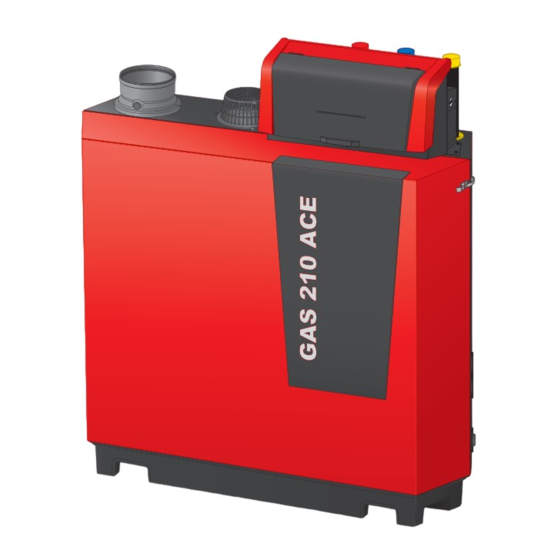
- Page 1 United Kingdom Service manual High-efficiency standing gas boiler Gas 210 Ace 80 - 120 - 160 - 200...
- Page 2 Dear Customer, Thank you very much for buying this appliance. Please read through the manual carefully before using the product, and keep it in a safe place for later reference. In order to ensure continued safe and efficient operation we recommend that the product is serviced regularly.
-
Page 3: Table Of Contents
Contents Contents About this manual ................. . . 5 Additional documentation . - Page 4 Contents 6.4.5 Status and sub-status ..............43 Maintenance .
-
Page 5: About This Manual
Description of the product Boiler types The following boiler types are available: Tab.1 Boiler types Name Heat exchanger size Output Gas 210 Ace 80 93 kW 3 sections Gas 210 Ace 120 129 kW 4 sections Gas 210 Ace 160 179 kW... -
Page 6: Main Components
2 Description of the product Main components Fig.1 General 1 Flue gas outlet connection 2 Air inlet connection 3 Flow connection 4 Return connection 5 Gas supply connection 6 Control box 7 Data plate AD-3002429-01 Fig.2 Internal 1 Flue gas temperature sensor 2 Burner 3 Heat exchanger 4 Flame inspection glass... -
Page 7: Introduction To The E-Smart Controls Platform
2 Description of the product Fig.4 Control box 1 Display cover 2 Power button 3 Control panel 4 Service connector 5 Control box front part - for expansion PCBs and gateways 6 Control box rear part - for the control unit and expansion PCBs AD-3002432-01 Introduction to the e-Smart controls platform The Gas 210 Ace boiler is equipped with the e-Smart controls platform. -
Page 8: Use Of The Control Panel
3 Use of the control panel Tab.3 Specific devices delivered with the Gas 210 Ace boiler Name visible Software ver Description Function in display sion CU-GH13 Control unit CU-GH13 The CU-GH13 control unit handles all basic functionality of the Gas 210 Ace boiler. 1.94 Control panel HMI T-control The HMI T-control is the user interface to the Gas 210 Ace... -
Page 9: Description Of The Icons In The Display
3 Use of the control panel Fig.8 Items in the main menu A Date and time | Name of the screen (actual position in the menu) B Available menus C Brief explanation of the selected menu 11:20 ......Tab.4 Available menus for the user Description... -
Page 10: Installer Instructions
4 Installer instructions Icon Description Frost protection is enabled: Protect the boiler and installation from freezing in winter. Service notification: service needed. Installer contact details are displayed or can be filled in. Tab.7 Icons - On/off Icon Description Icon Description CH operation is enabled. -
Page 11: Accessing The Installer Level
4 Installer instructions Accessing the installer level Some settings are protected by installer access. Enable installer access in order to change these settings. Use the rotary knob to navigate. Use the button to confirm your selection. 1. Access the installer level via the tile: 1.1. -
Page 12: Commissioning The Appliance
4 Installer instructions Commissioning the appliance At first start-up of the appliance, the display will show the commissioning wizard. Depending on the appliance, some steps take a few minutes to complete, for example appliances that need to deaerate after installation or need to configure a boiler. -
Page 13: Saving The Commissioning Settings
4 Installer instructions Performing the full load test 1. Select the tile [ The Change load test mode menu appears. 2. Select the test Medium power. Fig.15 Full load test A Change load test mode B Medium power The full load test starts. The selected load test mode is shown in the 11:20 ... -
Page 14: Changing The Control Panel Settings
4 Installer instructions Tab.11 Icon Zone or function Description Internal DHW Domestic hot water produced by boiler CIRCA / CH Central heating circuit Auto filling CH Adjust or start the automatic filling unit Commercial boiler Gas boiler Gas fired appliance Gas boiler Shower time function Activate the shower time function... -
Page 15: Setting The Parameters
4 Installer instructions 3. Select Installer Details. 4. Enter the following data: Installer name Your company's name Installer phone Your company's phone number 4.5.3 Setting the parameters You can change the settings of the control unit and the connected expansion boards, sensors etc. to configure the installation. The factory settings support the most common heating systems. -
Page 16: Increasing The Domestic Hot Water Temperature Temporarily
4 Installer instructions Fig.18 The heating curve 5. Adjust the following parameters: 11:20 ......Tab.14 Settings ..Slope: Slope of the heating curve: ..Underfloor heating circuit: slope between 0.4 ..and 0.7 Radiator circuit: slope at approximately 1.5 .. -
Page 17: Viewing Production And Software Information
4 Installer instructions 2. Select Installation Setup. Enable installer access if Installation Setup is not available. 2.1. Select Enable installer access. 2.2. Use code 0012. 3. Select the zone or device you want to read out. 4. Select Parameters, counters, signals. 5. -
Page 18: Resetting Or Restoring Settings
4 Installer instructions Resetting or restoring settings 4.7.1 Resetting the configuration numbers CN1 and CN2 The configuration numbers must be reset when indicated by an error message or when the control unit has been replaced. The configuration numbers can be found on the data plate of the appliance. Important All custom settings will be erased when the configuration numbers are reset. -
Page 19: Resetting To Factory Settings
(1 year) for a commercial boiler in a normal heating set-up. 4.8.2 Changing the ΔT setting The ΔT is factory set to 25 °C. It can be increased by a Remeha service technician. Contact Remeha for more information. Important When increasing the ΔT, the control unit limits the flow temperature to a maximum of 80 °C. -
Page 20: Cascade Control
4 Installer instructions Important The settings for these temperatures must follow the screed layer's recommendations. Activation of this function via the parameter ZP090 deactivates all other regulator functions in the zone. When the screed drying function is active on one circuit, all other circuits and the domestic hot water circuit continue to run. -
Page 21: Installation Examples
5 Installation examples Fig.24 Traditional cascade control 1 First boiler starts running when system temperature is 3°C below management set point. 2 After 4 minutes the second boiler starts running if ΔT< 6K and the system temperature is still more than 3°C below set point. 3 After 8 minutes the third boiler starts running if ΔT<... -
Page 22: Connecting Diagrams
5 Installation examples Connecting diagrams 5.2.1 1 boiler - 1 circuit (radiator) - DHW cylinder with loop Fig.27 Diagram and components - 6000037 CircA CircB CircC CB-01 SCB-10 AD-6000037-01 CircA Circuit A (radiator) P8 Circuit A pump CircB Circuit B P13 DHW charging pump CircC Circuit C P15 DHW circulation loop pump... -
Page 23: Boiler - 2 Circuits (Radiator, Underfloor Heating) - Dhw Cylinder With Loop
5 Installation examples Code Display text Menu path Set to CP024 Zone Function 0 = Disable > Installation Setup > SCB-10 > AUX 1 > Parameters, counters, signals > Parameters > General CP294 ConfigZonePump 8 = DHW looping > Installation Setup > SCB-10 > AUX 1 > Parameters, counters, signals >... -
Page 24: Cascade Of 2 Boilers - 2 Circuits (Radiator, Underfloor Heating)
5 Installation examples Code Display text Menu path Set to DP007 Dhw 3wv Standby 0 = CH position > Installation Setup > CU-GH13 > Internal DHW > Parameters, counters, signals > Parameters > General CP020 Zone Function 1 = Direct >... - Page 25 5 Installation examples Fig.32 Electrical connections lead boiler A1 - CB-01, SCB-10 and AD249 Pump 0-10 On/Off CB-01 Tout AD-6000038-01 Status AD249 0-10V Tout R-Bus R-Bus R-Bus SCB-10 Tsyst Tsyst Tdhw Tflow Tflow Tflow +TA- S12 S9 AD-6000045-01 Fig.33 Electrical connections lag boiler A2 - CB-01 Pump 0-10 On/Off...
-
Page 26: Settings
6 Settings Settings Introduction to parameter codes Fig.35 Code on a HMI T-control The controls platform makes use of an advanced system to categorise parameters, measurements and counters. Knowing the logic behind these ......00:12 codes, makes it easier to identify them. The code consists of two letters .... -
Page 27: List Of Parameters
6 Settings Fig.39 Search 4. Select the search criteria (code): 4.1. Select the first letter (datapoint category)........00:12 4.2. Select the second letter (datapoint type)..........4.3. - Page 28 6 Settings Code Display text Description Adjustment range Submenu 80 CP550 Zone, fire Fire Place mode is active 0 = Off CIRCA place 1 = On CP570 ZoneTime Time Program of the zone se 0 = Schedule 1 CIRCA Prog Select lected by the user 1 = Schedule 2 2 = Schedule 3...
- Page 29 6 Settings Code Display text Description Adjustment range Submenu 80 AP073 Summer Win Outdoor temperature; Upper 15 – 30.5 °C Outdoor limit for heating tempera ture AP079 Building Iner Inertia of the building used for 0 – 10 Outdoor heat up speed tempera...
- Page 30 6 Settings Code Display text Description Adjustment range Submenu 80 CP730 Zone Heat up Selection of heat up speed of 0 = Extra Slow CIRCA speed the zone 1 = Slowest 2 = Slower 3 = Normal 4 = Faster 5 = Fastest CP740 Zone cool...
- Page 31 6 Settings Code Display text Description Adjustment range Submenu 80 ZP080 Screed end The end temperature for the 7 – 60 °C Direct temp 3 third step of screed drying zone ZP090 Screed drying Enable the screed drying of 0 = Off Direct enable the zone...
-
Page 32: Scb-01 Expansion Pcb Parameters
6 Settings Code Display text Description Adjustment range Submenu 80 DP003 Abs max fan Maximum fan speed on Do 1000 – 7000 Rpm Gas fired 5100 6400 4800 5700 mestic Hot Water appliance DP010 Hysteresis Temperature hysteresis for 1 – 10 °C Gas fired the heat generator to start on appliance... -
Page 33: Scb-02 Expansion Pcb Parameters
6 Settings Tab.26 Factory settings at installer level Code Display text Description Adjustment range Submenu Default setting EP018 Status relay func. Status relay function 0 = No Action Status infor No Ac 1 = Alarm mation tion 2 = Alarm Inverted 3 = Generator on 4 = Generator off 5 = Reserved... - Page 34 6 Settings Tab.28 Factory settings at basic installer level Code Display text Description Adjustment range Submenu Default setting AP074 Force summer The heating is stopped, Hot water is 0 = Off Outdoor mode maintained, Force summer mode 1 = On temperature CP010 Tflow setpoint...
- Page 35 6 Settings Tab.29 Navigation for installer level Level Menu path Installer > Installation Setup > SCB-02 > Submenu > Parameters, counters, signals > Parameters > General (1) See the column "Submenu" in the following table for the correct navigation. The parameters are grouped in specific functionalities. Tab.30 Factory settings at installer level Code...
- Page 36 6 Settings Code Display text Description Adjustment range Submenu Default setting CP220 Zone HCZP Re Reduced footpoint of the temperature 15 - 90 °C DHW 1 15 °C CP221 duced of heat curve of the circuit CIRCB 1 15 °C CP230 Zone Heating Heating curve temperature gradient...
- Page 37 6 Settings Code Display text Description Adjustment range Submenu Default setting CP630 StartdayAntileg Startday of the function antilegionella 1 = Monday DHW 1 Satur CP631 zone of the zone 2 = Tuesday CIRCB 1 3 = Wednesday Satur 4 = Thursday 5 = Friday 6 = Saturday 7 = Sunday...
-
Page 38: List Of Measured Values
6 Settings Tab.31 Navigation for advanced installer level Level Menu path Advanced installer > Installation Setup > SCB-02 > Submenu > Parameters, counters, signals > Parameters > Advanced (1) See the column "Submenu" in the following table for the correct navigation. The parameters are grouped in specific functionalities. Tab.32 Factory settings at advanced installer level Code... - Page 39 6 Settings Tab.34 Counters at basic installer level Code Display text Description Range Submenu AC001 Hours on mains Number of hours that the appliance has 0 - 4294967295Hours System Func been on mains power tionality AC002 Service run hours Number of hours that the appliance has 0 - 131070Hours Gas fired ap...
-
Page 40: Scb-01 Expansion Pcb Counters
6 Settings Tab.37 Navigation for advanced installer level Level Menu path Advanced installer > Installation Setup > CU-GH13 > Submenu > Parameters, counters, signals > Counters > Advanced (1) See the column "Submenu" in the following table for the correct navigation. The counters are grouped in specific functionalities. (2) The counters can also be accessed directly via the Search datapoints function: >... - Page 41 6 Settings Code Display text Description Range Submenu AM016 System Flow Temp Flow temperature of appliance. -327.68 - 327.67°C Zone manag Producer Ge neric Gas fired ap pliance Prod manager bridge AM017 T heat exchanger The temperature of heat exchanger -25 - 150°C Gas fired ap...
- Page 42 6 Settings Tab.44 Signals at installer level Code Display text Description Range Submenu AM006 Release input Current status of the release input 0 = Open Gas fired ap 1 = Closed pliance 2 = Off AM036 Flue gas tempera Temperature of the exhaust gas leaving 0 - 250°C Gas fired ap...
-
Page 43: Scb-01 Expansion Pcb Signals
6 Settings Code Display text Description Range Submenu AM043 Pwr dwn reset nee A power down reset is needed 0 = No Gas fired ap 1 = Yes pliance AP078 Out sensor detec Outside sensor detected in the applica 0 = No Outdoor tem... - Page 44 6 Settings Code Display text Explanation Manual Heat Demand Manual heat demand for central heating is active. Frost Protection Frost protection mode is active. Reset In Progress The appliance resets. Halted The appliance has stopped. It must be reset manually. Factory test The factory test mode is active.
-
Page 45: Maintenance
7 Maintenance Code Display text Explanation Init safety unit The safety unit is initialising. Init blocking The blocking is initialising. StateUnknown The sub state is undefined. SuOutOfResetsWait1Hr The safety unit is blocking due to too many resets. Wait for 60 minutes or turn the power off and on again. -
Page 46: Opening The Boiler
7 Maintenance Opening the boiler Fig.41 Removing the panel 1. Unlock the over centre latches on both sides of the boiler. 2. Remove the panel. AD-3002452-01 Standard inspection and maintenance operations For a service, always perform the following standard inspection and maintenance operations. - Page 47 3. Compare the measured value with the checking values in the table. Tab.51 Checking/setting values for O at full load for G20 (H gas) Values at full load for G20 (H gas) Gas 210 Ace 80 3,9 – 5,2 – 6,5 8,1 – 8,8 – 9,5 Gas 210 Ace 120 3,9 –...
- Page 48 3. Compare the measured value with the checking values in the table. Tab.53 Checking/setting values for O at low load for G20 (H gas) Values at low load for G20 (H gas) Gas 210 Ace 80 3,8 – 4,3 – 9,6 Gas 210 Ace 120 3,8 – 4,3 –...
-
Page 49: Checking The Water Quality
7 Maintenance Fig.45 Adjusting screw B 5. Use the adjustment screw B to set the percentage of O for the gas type being used to the nominal value. Increasing the gas flow, will decrease O and increase CO . The direction in which the adjusting screw must be turned to increase or decrease the gas flow is indicated on the gas control valve. -
Page 50: Specific Maintenance Work
7 Maintenance Fig.47 Positive (+) side of the air pressure 4. Disconnect the silicon hose from the + side (A1) of the air pressure differential switch differential switch. 5. Connect a hose to the + side of the air pressure differential switch. 6. -
Page 51: Cleaning The Fan And Venturi
7 Maintenance 7.4.1 Cleaning the fan and venturi 3- to 4-section boilers Fig.49 Disassembling the fan unit 1. Remove the electrical connections from the fan. 2. Remove the air inlet silencer from the venturi. 3. Unscrew the nut under the gas control valve. 4. -
Page 52: Replacing The Ionisation/Ignition Electrode
7 Maintenance Fig.52 Cleaning the fan and venturi 6. Disconnect the fan from the venturi. 7. Clean the fan with compressed air. 8. Clean the venturi with a soft plastic brush. 9. Reassemble the unit in reverse order. AD-3002495-01 7.4.2 Replacing the ionisation/ignition electrode The ionisation/ignition electrode must be replaced if: The ionisation current is lower than 4 µA. -
Page 53: Cleaning The Heat Exchanger
7 Maintenance Fig.56 Cleaning the burner 4. Clean the outside of burner using compressed air with a pressure of 2 to 5 bar. Caution Maintain a minimum distance of 1 cm from the surface of the burner. Never clean the burner's surface with a brush or similar item. min. -
Page 54: Cleaning The Condensate Collector
7 Maintenance Fig.60 Cleaning the heat exchanger 6. Fit the inspection cover and the gasket with a new silicon cord. 7. Use clean water to thoroughly rinse the heat exchanger from the burner area. AD-3002499-01 7.4.5 Cleaning the condensate collector Fig.61 Cleaning the condensate collector 1. -
Page 55: Assembly After Maintenance
7 Maintenance 7.4.7 Assembly after maintenance 3- to 4-section boilers Fig.64 Mounting the burner 1. Mount the burner. The burner has one slot at the front. Position this over the pin at the burner opening. 2. Place a new burner gasket. 3. - Page 56 7 Maintenance 5- to 6-section boilers Fig.67 Mounting the burner 1. Mount the burner. The burner has one slot at the front. Position this over the pin at the burner opening. 2. Place a new burner gasket. 3. Mount the adapter. 4.
-
Page 57: Finalising Work
The meaning of the code can be found in the various error code tables. Important The error code is needed to find the cause of the error quickly and correctly and for any support from Remeha. 8.1.1 Display of error codes... -
Page 58: Warning
Only qualified professionals are authorised to work on the appliance and system. The error code remains visible until the problem is solved. 3. Note the error code when the problem cannot be resolved. 4. Contact Remeha for support. 8.1.2 Warning Tab.56... -
Page 59: Blocking
8 Troubleshooting Code Display text Description Solution A.02.49 Failed Init Node Failed Initialising Node SCB not found: Carry out an auto-detect A.02.55 Inval or miss SerNR Invalid or missing device serial num Contact your supplier. A.03.17 Safety check Periodically safety check ongoing Safety check procedure active: No action 8.1.3... - Page 60 8 Troubleshooting Code Display text Description Solution H.01.07 Max Delta TH-TR Maximum difference between heat Maximum difference between heat exchanger exchanger temperature and return and return temperature exceeded: temperature No flow or insufficient flow: Check the circulation (direction, pump, valves). Check the water pressure.
- Page 61 8 Troubleshooting Code Display text Description Solution H.02.00 Reset In Progress Reset In Progress Reset procedure active: No action H.02.02 Wait Config Number Waiting For Configuration Number Configuration error or unknown configuration number: Reset CN1 and CN2 H.02.03 Conf Error Configuration Error Configuration error or unknown configuration number:...
-
Page 62: Locking
8 Troubleshooting Code Display text Description Solution H.03.00 Parameter Error Safety parameters level 2, 3, 4 are Parameter error: security kernel not correct or missing Restart the boiler Replace the CU-GH H.03.01 CU to GVC data error No valid data from CU to GVC re Communication error with the CU-GH: ceived Restart the boiler... - Page 63 8 Troubleshooting Code Display text Description Solution E.00.08 THeat Ex Open Heat exchanger temperature sensor Heat exchanger temperature sensor open: is either removed or measures a Bad connection: check the wiring and connec temperature below range tors. Incorrectly fitted sensor: check that the sensor has been correctly fitted.
- Page 64 8 Troubleshooting Code Display text Description Solution E.02.04 Parameter Error Parameter Error Configuration error: Reset CN1 and CN2 The data plate for the CN1 and CN2 values. E.02.13 Blocking Input Blocking Input of the Control Unit Blocking input is active: from device external environment External cause: remove external cause Wrong parameter set: check the parameters...
- Page 65 8 Troubleshooting Code Display text Description Solution E.04.07 TFlow Sensor Deviation in flow sensor 1 and flow Flow temperature sensor deviation: sensor 2 detected Bad connection: check the connection Faulty sensor: replace the sensor E.04.08 Safety input Safety input is open Air pressure differential switch activated: Bad connection: check the wiring and connec...
-
Page 66: Error History
8 Troubleshooting Code Display text Description Solution E.04.13 Fan speed has exceeded normal op Fan fault: erating range Bad connection: check the wiring and connec tors. Fan operates when it should not be operating: check for excessive chimney draught Faulty fan: replace the fan E.04.15 FlueGas Pipe Blocked The flue gas pipe is blocked... -
Page 67: Technical Specifications
9 Technical specifications Fig.71 Error details 3. Select the error code you want to investigate. The display shows an explanation of the error code and several ....22/02/2018 11:20 ... details of the appliance when the error occurred. Error Code: A.00.00 4. -
Page 68: Bluetooth ® Wireless Technology
Only replace defective or worn boiler parts with original parts or recommended parts. Send the part to be replaced to the Remeha Quality Control department if the relevant part is covered by the guarantee (see the General Terms of Sale and Delivery). - Page 69 10 Spare parts 7837115 - v.01 - 10012023...
- Page 70 10 Spare parts 7837115 - v.01 - 10012023...
- Page 71 Original instructions - © Copyright All technical and technological information contained in these technical instructions, as well as any drawings and technical descriptions supplied, remain our property and shall not be multiplied without our prior consent in writing. Subject to alterations.
- Page 72 T +44 (0)330 678 0140 E technical@remeha.co.uk W www.remeha.co.uk Remeha Commercial UK Brooks House Coventry Road Warwick CV34 4LL 7837115 - v.01 - 10012023 7837115...
Need help?
Do you have a question about the Gas 210 Ace 80 and is the answer not in the manual?
Questions and answers