Table of Contents
Advertisement
Quick Links
Advertisement
Table of Contents

Related Manuals for AXIOMTEK rBOX510-6COM


Summary of Contents for AXIOMTEK rBOX510-6COM
- Page 1 Robust Din-rail Fanless Embedded System User’s Manual...
- Page 2 Axiomtek does not make any commitment to update the information in this manual. Axiomtek reserves the right to change or revise this document and/or product at any time without notice.
-
Page 3: Safety Precautions
Safety Precautions Before getting started, please read the following important safety precautions. The rBOX510-6COM does not come equipped with an operating system. An operating system must be loaded first before installing any software into the computer. Be sure to ground yourself to prevent static charge when installing the internal components. -
Page 4: Classification
Classification Degree of production against electric shoc k: not classified Degree of protection against the ingress of water: IP30 Equipment not suitable for use in the presence of a flammable anesthetic mixture with air or with oxygen or nitrous oxide. Mode of operation: Continuous Type of protection against electric shock: Class I equipment General Cleaning Tips... - Page 5 Cleaning Tools Although many companies have created products to help improve the process of cleaning your computer and peripherals users can also use household items to clean their computers and peripherals. Below is a listing of items you may need or want to use while cleaning your computer or computer peripherals.
-
Page 6: Scrap Computer Recycling
If the computer equipments need the maintenance or are beyond repair, we strongly recommended that you should inform your Axiomtek distributor as soon as possible for the suitable solution. For the computers that are no longer useful or no longer working well, please contact your Axiomtek distributor for recycling and we will make the proper arrangement. -
Page 7: Table Of Contents
Table of Contents Safety Precautions ....................iii Classification ......................iv General Cleaning Tips ..................iv Scrap Computer Recycling .................. vi CHAPTER 1 INTRODUCTION ............... 1 General Description ................1 System Specifications ............... 2 1.2.1 CPU ........................2 1.2.2 BIOS ........................2 1.2.3 System Memory .................... - Page 8 APPENDIX B DIO Command ..............59 How to Use DIO Registers ................59 viii...
-
Page 9: Chapter 1 Introduction
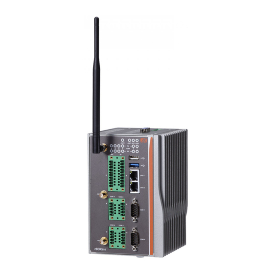
User’s Manual CHAPTER 1 INTRODUCTION This chapter contains general information and detailed specifications of the rBOX510-6COM. The Chapter 1 includes the following sections: General Description System Specification Dimensions I/O Outlets General Description rBOX510-6COM Din-rail fanless embedded system is suitable for communications control and for protocol converter applications in critical environments. -
Page 10: System Specifications
User’s Manual Embedded O.S. Supported ® ® rBOX510 not only supports Windows 7 and Windows 8, but also supports ® ® embedded OS, such as W indows 7 embedded, W indows 8 embedded and Linux package support. For storage device, rBOX510 supports one SATA SSD ™... -
Page 11: Wireless
User’s Manual 1.2.7 Wireless 3 x Full size Mini Card slot supports 3G/GPRS and Wifi. 2 x SIM Card Socket. 3 x Antenna holes. 1.2.8 1 x USB2.0 & 1 x USB3.0 USB Pin Define USB2.0... -
Page 12: Power
User’s Manual COM3~6 RS-232 RS-422 RS-485 Data+ Data- 5,10 ISO_GND ISO_GND ISO_GND 1.2.10 Power Signal Alarm+ Alarm- Power Fail Shield Ground PF pin must connect to external the power fail of UPS, so can normal shutdown when being abnormal power loss. - Page 13 User’s Manual Relay output Below is a very simple application for remote notice use relay and lamp. a) Normal b) W arning Introduction...
- Page 14 User’s Manual c) Relay wiring of rBox Introduction...
-
Page 15: Watchdog Timer (Wdt)
User’s Manual 1.2.11 WatchDog Timer (WDT) One step is 1sec, 255 levels One step is 1sec/1min, 255 levels. 1.2.12 Digital I/O Connector and Pin Definition 8bit DI and 8bit DO 3KV optical isolation DIO Design Sepcification... - Page 16 User’s Manual Remark Signal Name Meaning COM+ Plus common for Input/ Output Group COM- Minus common for Input/Output Group DIN0~7 Input Group DOUT0~7 Output Group DIO 8 in/out of TB20 Female Function Function COM+ COM+ COM- COM- SMBus Address &...
- Page 17 User’s Manual PIN11 DI7 PIN20 DO7 SMBus to GPIO Schematic Introduction...
- Page 18 User’s Manual DIO operation schematic diagram Reference 1. Reference 2. Introduction...
- Page 19 User’s Manual Reference 3 Digital Input Wiring Reference 4 Digital Output Wiring Introduction...
-
Page 20: Ethernet Ports
User’s Manual 1.2.13 Ethernet Ports LAN 1 and LAN 2 The board has dual RJ-45 ethernet connector which using Intel I210-IT ethernet controllers, support 1000/100/10-Base transmit rate and with 1.5KV magnetic isolated protection. Signal MDI0+ MDI0- MDI1+ MDI1-... -
Page 21: System Led
User’s Manual 1.2.14 System LED There are showed the LED’s indicators and functional descriptions. LED Name Description Color Indicate the Power status. Green LED will be on for green color when the power DC input is acceptable. LED will be on for red color when the power DC input isn’t acceptable or power fail event. -
Page 22: Operation Temperature
User’s Manual 1.2.15 Operation Temperature -40℃ ~ +70℃ 1.2.16 Storage Temperature -45℃ ~ +85℃ 1.2.17 Humidity 5% ~ 95% (non-condensation) 1.2.18 Weight 1.8kg 1.2.19 Dimensions 85.6mm(3.37”) (W) x110mm(4.33”) (D) x155mm(6.10”) (H) 1.2.20 System I/O Outlets ... -
Page 23: Dimensions
User’s Manual Dimensions The following diagrams show you dimensions and outlines of the rBOX510-6COM. Introduction... -
Page 24: I/O Outlets
User’s Manual I/O Outlets The following figures show you I/O outlets on front view and top view of the rBOX510-6COM. Introduction... - Page 25 User’s Manual Introduction...
- Page 26 User’s Manual This page is intentionally left blank. Introduction...
-
Page 27: Chapter 2 Hardware Installation
User’s Manual CHAPTER 2 HARDWARE INSTALLATION The rBOX510-6COM is convenient for your various hardware configurations, such as Hard Disk Drive. The chapter 2 will show you how to install the hardware. It includes: Installing the Hard Disk Drive Step 1 Turn off the system. - Page 28 User’s Manual Step 4 Insert the Hard Disk Drive into the bracket and use these screws to fix tightly. Note: The positive of Hard Disk Drive must be upward when insert the Hard Disk Drive into the bracket. Step 5 Connecting the SATA+Power HDD cable with Hard Disk Drive.
-
Page 29: Installing The Wireless Module
User’s Manual Installing the Wireless module rBOX510-6COM offers 3 solutions to install wireless module as follows: The wireless socket is near heatsink cover side, supports USB/PCIe interface. Two wireless sockets are near SSD cover side, one socket supports mSATA/USB/PCIe interface, another supports USB/PCIe interface only. - Page 30 Step 2 Loosen all screws of the cover and remove the cover from the system. Step 3 Take out the thermal pad form the wireless module kit, then stick on the thermal parts. Note: Must use the dedicated option wireless module kit for rBOX510-6COM. Hardware Installation...
- Page 31 User’s Manual Step 4 Plug the wireless module in the wireless socket and use screws to fix tightly. Step 5 Put the cover back to the system, and fasten screws tight close the chassis. Hardware Installation...
- Page 32 User’s Manual Step 6 Plug the SIM card into the SIM slot and the positive of SIM Card is as below picture. The external SIM socket dedicated for heatsink cover side wireless socket use. (Does not support SSD cover side...
- Page 33 User’s Manual Two wireless sockets are near SSD cover side. Step 1 Turn off the system. Step 2 Loosen all screws of the cover and remove the cover from the system. one socket supports mSATA/USB/PCIe interface Step 3 Plug the wireless module in the wireless socket and use screws to fix tightly.
- Page 34 User’s Manual another supports USB/PCIe interface only. Step 5 Put the SIM card into the SIM slot firstly. Step 6 Then plug the wireless module in the wireless socket and use screws to fix tightly. Step 7 Put the cover back to the system, and fasten screws tight close the chassis.
-
Page 35: Installing The Msata Module
User’s Manual Installing the mSATA module Step 1 Turn off the system. Step 2 Loosen all screws of the cover and remove the cover from the system. Step 3 Plug the mSATA module in the socket and use screws to fix tightly. -
Page 36: Installing Din-Rail Mounting
User’s Manual Installing Din-rail Mounting The rBOX provides Din-rail Mount that customers can install as below: Step 1 Prepare Din-rail Mount assembling components (screws and bracket) ready. Step 2 Assembly the bracket to the system, and fasten screws tight. - Page 37 User’s Manual Setting up rBOX series by Din-rail mounting The rBOX set up by Din-rail mounting as below: Step 1 Fixing the rail firstly. Step 2 Set up the rBOX on the rail by Din-rail mounting Hardware Installation...
-
Page 38: Installing Wall Mounting (Optional)
User’s Manual Installing Wall Mounting (optional) The rBOX provides Wall Mounting that customers can install as below: Step 1 Prepare Wall Mount assembling components (screws and bracket) ready. Step 2 Assembly the bracket to the system, and fasten screws tight. -
Page 39: Chapter 3 Ami Uefi Bios Utility
User’s Manual CHAPTER 3 AMI UEFI BIOS UTILITY The AMI UEFI BIOS provides users with a built-in Setup program to modify basic system configuration. All configured parameters are stored in a flash-backed-up to save the Setup information whenever the power is turned off... -
Page 40: The Main Menu
User’s Manual The Main Menu Once you enter the AMI BIOS Aptio Setup Utility, the Main Menu appears on the screen. In the Main Menu, there are several Setup functions and a couple of Exit options for your selection. Use Select Screen Keys (or Move Keys) to select the Setup Page you intend to configure then press <Enter>... -
Page 41: Advanced Features
User’s Manual Advanced Features This Advanced section allows users to configure and improve your system, to set up some system features according to your preference. You can select any of the items in the left frame of the screen to go to the sub menus: ... - Page 42 User’s Manual Mini Card configuration The default setting for mini card is PCIE. (Please refer below graphics.) Note: SSD and mSATA function can be either one, it can be select by BIOS menu. mSATA and wireless use the same slot, and only one of them can be selected.
- Page 43 User’s Manual COM Port Interface Type The default setting for all Serial Ports are RS232. You can change the setting by selecting the value you want in each COM Port Type. (Please refer below graphics.) AMI UEFI BIOS Utility...
- Page 44 User’s Manual AMI UEFI BIOS Utility...
- Page 45 User’s Manual AMI UEFI BIOS Utility...
- Page 46 User’s Manual Supports internal 120 ohms terminator in RS422 & RS485 mode. (Please refer below graphics.) AMI UEFI BIOS Utility...
- Page 47 User’s Manual H/W Monitor Scroll to this item and press <Enter> to view the monitor hardware status. (Please refer below graphics.) AMI UEFI BIOS Utility...
- Page 48 User’s Manual AMI UEFI BIOS Utility...
- Page 49 User’s Manual DIO Configuration The DIO Modifacation default setting is “disable”. If the setting is changed for “enable”, you can load manufacture default and program DIO setting. (Please refer below graphics.) AMI UEFI BIOS Utility...
- Page 50 User’s Manual AMI UEFI BIOS Utility...
- Page 51 User’s Manual AMI UEFI BIOS Utility...
- Page 52 User’s Manual CPU Configuration Scroll to this item and press <Enter> to view the CPU Configuration informations. (Please refer below graphics.) AMI UEFI BIOS Utility...
- Page 53 User’s Manual AMI UEFI BIOS Utility...
- Page 54 User’s Manual IDE Configuration Scroll to this item and press <Enter> to view the IDE Configuration informations. (Please refer below graphics.) AMI UEFI BIOS Utility...
- Page 55 Utility Configuration BIOS flash utility is a tool for flash BIOS on setup menu, follow the step to flash BIOS. Create a folder and rename to Axiomtek on the root of USB storage (Ex: X:\Axiomtek) Copy BIOS file to the Axiomtek folder (Ex: X:\Axiomtek\CEM840A.104) (Note : BIOS file nemae must contain...
- Page 56 User’s Manual AMI UEFI BIOS Utility...
-
Page 57: Chipset Feature
User’s Manual Chipset Feature This section contains completely optimized chipset ’s features in the system AMI UEFI BIOS Utility... - Page 58 User’s Manual USB Configuration Scroll to this item and press <Enter> to view the USB Configuration informations. (Please refer below graphics.) AMI UEFI BIOS Utility...
- Page 59 User’s Manual AMI UEFI BIOS Utility...
-
Page 60: Security
User’s Manual Security The default setting for Administrator Password is “Not setting passwords”. The Security menu allows users to change the security settings for the system. You can set the password for both Administrator Password and User Password. (Please refer below graphics.) -
Page 61: Boot Type
User’s Manual Boot Type The Boot Option Priorities can select by Boot Option #1, #2… (Please refer below graphics.) AMI UEFI BIOS Utility... - Page 62 User’s Manual Hard Drive BBS Priorites supports the hard drive boot option. AMI UEFI BIOS Utility...
-
Page 63: Save & Exit
User’s Manual Save & Exit This section allows you to determine whether or not to accept your modifications. Type “Y” to quit the setup utility and save all changes. Type “N” to bring you back to the Previous Setup utility. - Page 64 User’s Manual AMI UEFI BIOS Utility...
-
Page 65: Appendix Awatchdog Timer
User’s Manual APPENDIX A WATCHDOG TIMER About Watchdog Timer After the system stops working for a while, it can be auto-reset by the watchdog timer. The integrated watchdog timer can be set up in the system reset mode by program. - Page 66 User’s Manual Set timer unit: O 2E F5 O 2F 71 ; (71: Sec; 79:Minute) Disable WDT Enable configuration: O 2E 87 ; Un-lock super I/O O 2E 87 Select logic device: O 2E 07 O 2F 07 ...
- Page 67 User’s Manual APPENDIX B DIO Command How to Use DIO Registers DIO Command...
- Page 68 User’s Manual This page is intentionally left blank. DIO Command...
Need help?
Do you have a question about the rBOX510-6COM and is the answer not in the manual?
Questions and answers