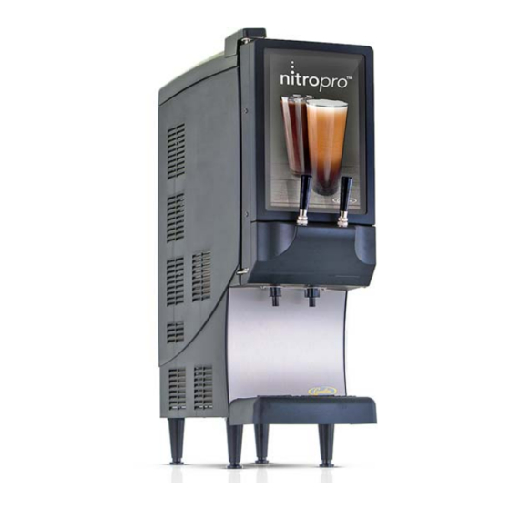
Cornelius NITROPRO MINI Service And Preventative Maintenance Manual
Specialty beverage dispenser
Hide thumbs
Also See for NITROPRO MINI:
- Service and preventative maintenance manual (40 pages) ,
- Installation and operator's manual (36 pages) ,
- Instructions (2 pages)
Table of Contents
Advertisement
Quick Links
Advertisement
Table of Contents

Related Manuals for Cornelius NITROPRO MINI


Summary of Contents for Cornelius NITROPRO MINI
- Page 1 SPECIALTY BEVERAGE DISPENSER NITROPRO MINI Service and Preventative Maintenance Manual Release Date: 2/15/19 Publication Number: 548000106SER Revision Date: 2/15/19 Revision: Rev. 2.0 Model: CNB Mini Visit web site http://cornelius-usa.com and create an account for all your literature needs.
- Page 2 This Product is warranted only as provided in Cornelius’ Commercial Warranty applicable to this Product and is subject to all of the restrictions and limitations contained in the Commercial Warranty.
-
Page 3: Table Of Contents
Table of Contents 1.0 SAFETY 2.0 OVERVIEW AND REQUIRED TOOLS 2.1 Nitropro Functions & Specifications 2.2 Key Components 2.3 Required Tools 3.0 SYSTEM OPERATION 3.1 Facility Supplies 3.2 Operating Processes 3.3 Component Functions 3.3.1 Tap Handles 3.3.2 Product Concentrate Pump 3.3.3 Water Inlet Solenoid 3.3.4 Air Compressor &... - Page 4 Table of Contents 5.0 TROUBLESHOOTING Table 5-1 - Systems-Level Troubleshooting Table 5-2 - Drink-Quality Troubleshooting Table 5-3 - Compressed Air & Infusion Troubleshooting Table 5-4 - Dispensing-Function Troubleshooting 5.1 Air-Compressor Pressure Verification 6.0 COMPONENT REPLACEMENT 6.1 Safety Precautions 6.3 Access Panel Removal 6.3 Main PCB 6.4 Mixing-Dispensing Assembly Components 6.4.1 Air Pressure Regulator...
-
Page 5: Safety
COULD RESULT IN SERIOUS INJURY, DEATH OR EQUIPMENT DAMAGE. IF THE SUPPLY CORD IS DAMAGED, IT MUST BE REPLACED BY THE MANUFACTURER, ITS SERVICE AGENT OR SIMILARLY QUALIFIED PERSONS IN ORDER TO AVOID A HAZARD. © 2019, Cornelius Inc. All Rights Reserved - 1 - Publication Number: 548000106SER... - Page 6 140 lbs. (63.5 kg.) to insure adequate support for the unit. FAILURE TO COMPLY COULD RESULT IN SERIOUS INJURY, DEATH OR EQUIPMENT DAMAGE. THE APPLIANCE MUST BE ORIENTED IN A VERTICAL POSITION. Publication Number: 548000106SER - 2 - © 2019, Cornelius Inc. All Rights Reserved...
-
Page 7: Overview And Required Tools
2.0 OVERVIEW AND REQUIRED TOOLS 2.1 Nitropro Functions & Specifications Table 2-4 - Water Requirements The Nitropro Mini dispenses still or air-injected, chilled Nitro coffee at the pull of a tap handle. 35 psig (241 kPa) Min. 90 psig (621 kPa) Max. -
Page 8: Key Components
Nitropro Mini Service Manual 2.0 BREWER OVERVIEW AND REQUIRED TOOLS (Cont.) 2.2 Key Components The Nitropro Mini consists of these main controls System Controller Board (Main PCB) and components (refer to Figs. 2-1 and 2.2). Manages system events and device interactions. - Page 9 Nitropro Mini Service Manual 2.0 BREWER OVERVIEW AND REQUIRED TOOLS (Cont.) 2.2 Key Components (Cont.) Figure 2-2 - Main Components © 2019, Cornelius Inc. All Rights Reserved - 5 - Publication Number: 548000106SER...
-
Page 10: Required Tools
Cleaning Brushes Bristle and Wire Air Pressure Gauge Capable of 100 psi (689 kPa) with high-pressure hose and 1/4”push-connect fitting Hose-Clamp Crimping/Cutting Tool Oetiker HIP 2800 Es Publication Number: 548000106SER - 6 - © 2019, Cornelius Inc. All Rights Reserved... -
Page 11: System Operation
Nitropro Mini Service Manual 3.0 SYSTEM OPERATION This section describes how the Nitropro Mini dis- penser operates. By grasping the details of the operating process for still and Nitro coffee dis- pensing, you will have the knowledge to detect many of the common malfunctions. -
Page 12: Operating Processes
The low-pressure path is to the still-coffee dispense manifold in which the dispense solenoid valve is open. Figure 3-3 - Still Coffee Dispense Process Publication Number: 548000106SER - 8 - © 2019, Cornelius Inc. All Rights Reserved... - Page 13 The low-pressure path is to the Nitro-coffee dispense manifold in which the dispense solenoid valve is open. Figure 3-4 - Nitro Coffee Dispense Process © 2019, Cornelius Inc. All Rights Reserved - 9 - Publication Number: 548000106SER...
-
Page 14: Component Functions
The peristaltic pump is driven by a 24V DC servo concentrate per unit time. motor. A maintenance kit for the pump includes a replacement pump hose with nipple ends. Publication Number: 548000106SER - 10 - © 2019, Cornelius Inc. All Rights Reserved... -
Page 15: Water Inlet Solenoid
95 psi (655 kPa) in the event of pump-motor runaway. Figure 3-11 - Mixing-Infusion Manifold & Check Valves Figure 3-10 - Air Compressor and Air Storage © 2019, Cornelius Inc. All Rights Reserved - 11 - Publication Number: 548000106SER... -
Page 16: Dispense Manifold
3.3.7 Power Supply (24Vdc) This unit provides DC power for the air compres- sor and the Main PCB. Figure 3-14 - Mixing-Dispensing Assembly Figure 3-13 - 24Vdc Power Supply Publication Number: 548000106SER - 12 - © 2019, Cornelius Inc. All Rights Reserved... -
Page 17: Ice Bank Chilling System
Figure 3-16 - Ice Bank Sensor & Agitator Motor Figure 3-15 - Ice Bank and Controller Module © 2019, Cornelius Inc. All Rights Reserved - 13 - Publication Number: 548000106SER... -
Page 18: Front-Door Control Switches
(5:1). When the switch is returned to the ON position, the mix- ing ratio returns to that selected on the pump mix-ratio switch bank (Fig. 3-8). Publication Number: 548000106SER - 14 - © 2019, Cornelius Inc. All Rights Reserved... -
Page 19: Preventative Maintenance
Add water until a trickle runs out of the black overflow tube. 4) Cap the fill tube and return it to its storage Figure 4-1 - Fans position. © 2019, Cornelius Inc. All Rights Reserved - 15 - Publication Number: 548000106SER... -
Page 20: Product Pump Mix-Ratio Verification
On, with all others Off. is between 35 to 45°F. NOTE: Drink temperature must be maintained to properly set the ratio of the unit. Publication Number: 548000106SER - 16 - © 2019, Cornelius Inc. All Rights Reserved... - Page 21 8) Pull the Left Tap Handle for 5 seconds or until ished drink to the Brix refractometer meter coffee is darker and only concentrate is dis- lens. pensed. 4) Check the Brix value on the meter. © 2019, Cornelius Inc. All Rights Reserved - 17 - Publication Number: 548000106SER...
-
Page 22: Components Visual Inspection
Figure 4-5 - Concentrate Pump & Overhaul Kit dispensing tube, outlet-cap nipple that inserts into the manifold. If the manifold drips, check Publication Number: 548000106SER - 18 - © 2019, Cornelius Inc. All Rights Reserved... - Page 23 Fig. 4-5 so that only one point on the hose must be compressed. 11) Reinstall the pump cover. 12) Install the pump on the baseplate and recon- nect the hoses. © 2019, Cornelius Inc. All Rights Reserved - 19 - Publication Number: 548000106SER...
-
Page 24: Troubleshooting
C. Measure power input to Main PCB. C. No power to Main PCB control board or Replace fuse or board if necessary (see Fig. board has failed 6-1) Publication Number: 548000106SER - 20 - © 2019, Cornelius Inc. All Rights Reserved... - Page 25 C. Check/replace agitator motor, check cold output is restricted water lines & flow D. Loss of refrigerant charge due to leak in D. Repair leak, recharge system system © 2019, Cornelius Inc. All Rights Reserved - 21 - Publication Number: 548000106SER...
- Page 26 & shut off at 80 psi. Release stem and if it still leaks, replace D. Air-storage relief valve worn out the relief valve Publication Number: 548000106SER - 22 - © 2019, Cornelius Inc. All Rights Reserved...
- Page 27 B. Water inlet solenoid binding or pressure- provided to unit while dispensing control components are malfunctioning B. Clean and/or replace as necessary C. Concentrate pump malfunctioning C. Verify operation, replace as necessary © 2019, Cornelius Inc. All Rights Reserved - 23 - Publication Number: 548000106SER...
-
Page 28: Air-Compressor Pressure Verification
75 to 85 psi (517 to 586 kPa). If the pres- sure is out of range, check for leaks and check/ replace the storage-chamber pressure switch. Publication Number: 548000106SER - 24 - © 2019, Cornelius Inc. All Rights Reserved... -
Page 29: Component Replacement
6.0 COMPONENT REPLACEMENT This section provides instructions or guidelines on NOTE: Use the hinge cover to collect the panel screws removed. replacing the various Nitropro Mini components. 6.1 Safety Precautions WARNING! Disconnect power to the unit before servic- ing or replacing electrical components. Fol- l ow a l l l o c k o u t / ta g o u t p ro c e d u re s established by the user. - Page 30 Nitropro Mini Service Manual 6.0 COMPONENT REPLACEMENT (Cont.) 6.2 Access Panel Removal (Cont.) Publication Number: 548000106SER - 26 - © 2019, Cornelius Inc. All Rights Reserved...
-
Page 31: Main Pcb
Nitropro Mini Service Manual 6.0 COMPONENT REPLACEMENT (Cont.) 6.3 Main PCB 1) Shut off power to the Nitropro Mini and unplug its power cord from the wall receptacle. 2) Remove the drip tray and splash plate. 3) Remove the Phillips screw securing the metal housing of the Main PCB (Fig. -
Page 32: Mixing-Dispensing Assembly Components
4) On the new regulator, turn its adjustment knob Figure 6-2 - Mixing-Dispensing Assembly in Cabinet clockwise until it stops (closed). Then open it the number of turns counted in step 3. Publication Number: 548000106SER - 28 - © 2019, Cornelius Inc. All Rights Reserved... -
Page 33: Mixing - Infusion Manifold
Figure 6-6 - Dispense Manifold Assembly Be careful to avoid damaging the tubing when removing the hose clamp. 2) Unplug the two solenoid wires and disconnect the hose from its port. © 2019, Cornelius Inc. All Rights Reserved - 29 - Publication Number: 548000106SER... -
Page 34: Concentrate Pump
3) Disconnect the air filter from the air line by Figure 6-7 - Air Compressor and Storage Chamber pressing on the dark gray ring on the hose side of each connector while withdrawing the hose. Publication Number: 548000106SER - 30 - © 2019, Cornelius Inc. All Rights Reserved... -
Page 35: Water Inlet Solenoid
5) Remove the two back-panel, Phillips screws securing the inlet solenoid bracket. 6) Partially remove the inlet solenoid and then remove the dispenser water-inlet hose from it. © 2019, Cornelius Inc. All Rights Reserved - 31 - Publication Number: 548000106SER... -
Page 36: Merchandiser Led Back-Lighting Panel
NOTE: The ice sensor is located at the left-rear of the enclosure (Fig. 6-12) and sensor removal may be performed from the enclosure rear. Publication Number: 548000106SER - 32 - © 2019, Cornelius Inc. All Rights Reserved... -
Page 37: Agitator Motor
5) Install the new sensor in the ice bank. Route its cable to the controller module and plug it in. Figure 6-13 - Agitator Motor Location & Underside © 2019, Cornelius Inc. All Rights Reserved - 33 - Publication Number: 548000106SER... -
Page 38: Ice Bank Controller
6) Lift and angle the motor assembly to withdraw it from the ice bank. 7) Install the replacement motor in reverse order. Figure 6-16 - Ice Bank Controller Module Removal Publication Number: 548000106SER - 34 - © 2019, Cornelius Inc. All Rights Reserved... -
Page 39: Refrigeration Components
Figure 6-17 - Tap Handle/Microswitch Mounting helpful: Table 2-2 - Refrigerant Type 4) Carefully lift the surrounding plastic housing off of the tap-handle mounts to expose the microswitch assemblies. © 2019, Cornelius Inc. All Rights Reserved - 35 - Publication Number: 548000106SER... - Page 40 Reinstall the tap han- dles. 8) Verify operation of the taps. Publication Number: 548000106SER - 36 - © 2019, Cornelius Inc. All Rights Reserved...
-
Page 41: Appendix A - System Drawings
Nitropro Mini Service Manual APPENDIX A - SYSTEM DRAWINGS Figure A-1 - Plumbing Diagram © 2019, Cornelius Inc. All Rights Reserved - 37 - Publication Number: 548000106SER... - Page 42 Nitropro Mini Service Manual APPENDIX A - SYSTEM DRAWINGS (Cont.) Figure A-2 - Electrical Diagram Publication Number: 548000106SER - 38 - © 2019, Cornelius Inc. All Rights Reserved...
- Page 43 Nitropro Mini Service Manual © 2019, Cornelius Inc. All Rights Reserved - 39 - Publication Number: 548000106SER...
- Page 44 Nitropro Mini Service Manual Publication Number: 548000106SER - 40 - © 2019, Cornelius Inc. All Rights Reserved...
- Page 45 Cornelius Inc. www.cornelius-usa.com...
Need help?
Do you have a question about the NITROPRO MINI and is the answer not in the manual?
Questions and answers