Cornelius Nitropro Mini Service And Preventative Maintenance Manual
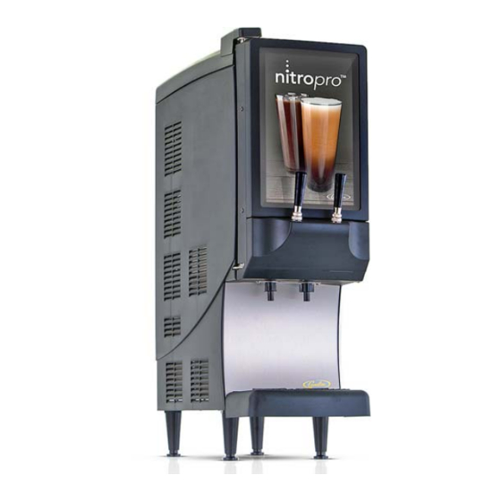
Specialty beverage dispenser
Hide thumbs
Also See for Nitropro Mini:
- Service and preventative maintenance manual (45 pages) ,
- Installation and operator's manual (36 pages) ,
- Instructions (2 pages)
Table of Contents
Advertisement
Advertisement
Table of Contents
Troubleshooting

Related Manuals for Cornelius Nitropro Mini


Summary of Contents for Cornelius Nitropro Mini
- Page 1 SPECIALTY BEVERAGE DISPENSER NITROPRO MINI Service and Preventative Maintenance Manual Release Date: 2/15/19 Publication Number: 548000106SER Revision Date: 10/24/19 Revision: Rev. A Visit web site http://cornelius-usa.com and create an account for all your literature needs.
- Page 2 This Product is warranted only as provided in Cornelius’ Commercial Warranty applicable to this Product and is subject to all of the restrictions and limitations contained in the Commercial Warranty.
-
Page 3: Table Of Contents
3.3.10 Front‐Door Control Switches ......... . . 14 © 2019, Cornelius Inc. All Rights Reserved ‐... - Page 4 Appendix B - Plumbing Schematic..........35 Publication Number: 548000106SER ‐ ii ‐ © 2019, Cornelius Inc. All Rights Reserved...
-
Page 5: Safety Instructions
OUS INJURY, DEATH OR EQUIPMENT DAMAGE. IF THE SUPPLY CORD IS DAMAGED, IT MUST BE REPLACED BY THE MANUFAC‐ TURER, ITS SERVICE AGENT OR SIMILARLY QUALIFIED PERSONS IN ORDER TO AVOID A HAZARD. © 2019, Cornelius Inc. All Rights Reserved ‐ 1 ‐... -
Page 6: Safety Precautions
When installing the unit on a counter top, the counter must be able to support a weight in excess of 185 lbs. (83.9 kg.) to insure adequate support for the unit. FAILURE TO COMPLY COULD RESULT IN SERIOUS INJURY, DEATH OR EQUIPMENT DAMAGE. THE APPLIANCE MUST BE PLACED IN A HORIZONTAL POSITION. Publication Number: 548000106SER ‐ 2 ‐ © 2019, Cornelius Inc. All Rights Reserved... -
Page 7: Overview And Required Tools
Table 2‐4 ‐ Water Requirements ITROPRO UNCTIONS PECIFICATIONS The Nitropro Mini dispenses still or air‐injected, chilled Nitro 40 psig (275.8 kPa) Min. coffee at the pull of a tap handle. Opening a tap automati‐ 65 psig (448.2 kPa) Max. Water Supply Pressure cally engages the product mixing pump (as well as the air (if >65 psi, install external pres‐... -
Page 8: Key Components
Nitropro Mini Service Manual 2.2 K OMPONENTS The Nitropro Mini consists of these main controls and com‐ ponents (refer to Figs. 2‐1 and 2.2). Dispensing Taps (Still & Nitro Coffee) Allow coffee dispensing. Pulling of tap handle triggers switch that activates outlet solenoid valve (in dispense man‐... - Page 9 Nitropro Mini Service Manual Figure 2‐2 ‐ Main Components © 2019, Cornelius Inc. All Rights Reserved ‐ 5 ‐ Publication Number: 548000106SER...
-
Page 10: Required Tools
Cleaning Brushes Bristle and Wire Air Pressure Gauge Capable of 100 psi (689 kPa) with high‐pressure hose and 1/ 4”push‐connect fitting Hose-Clamp Crimping/Cutting Tool Oetiker HIP 2800 Es Publication Number: 548000106SER ‐ 6 ‐ © 2019, Cornelius Inc. All Rights Reserved... -
Page 11: System Operation
Nitropro Mini Service Manual 3.0 SYSTEM OPERATION This section describes how the Nitropro Mini dispenser operates. By grasping the details of the operating process for still and Nitro coffee dispensing, you will have the knowl‐ edge to detect many of the common malfunctions. -
Page 12: Operating Processes
Note: There is no flow in the Nitro‐coffee circuit and infusion manifold since its dispense valve is closed. The low‐pressure path is to the still‐coffee dispense manifold in which the dispense solenoid valve is open. Figure 3‐3 ‐ Still Coffee Dispense Process Publication Number: 548000106SER ‐ 8 ‐ © 2019, Cornelius Inc. All Rights Reserved... -
Page 13: Right Tap Handle - Nitro Coffee Dispensing
Note: There is no flow in the still‐coffee circuit since its dispense valve is closed. The low‐pressure path is to the Nitro‐coffee dispense manifold in which the dispense solenoid valve is open. Figure 3‐4 ‐ Nitro Coffee Dispense Process © 2019, Cornelius Inc. All Rights Reserved ‐ 9 ‐ Publication Number: 548000106SER... -
Page 14: Component Functions
TDS value). The peristaltic pump is driven by a 24V DC servo motor. A maintenance kit for the pump includes a replacement pump hose with nipple ends. Publication Number: 548000106SER ‐ 10 ‐ © 2019, Cornelius Inc. All Rights Reserved... -
Page 15: Water Inlet Solenoid
95 psi (655 kPa) in the event of pump‐motor runaway. Figure 3‐11 ‐ Mixing‐Infusion Manifold & Check Valves Figure 3‐10 ‐ Air Compressor and Air Storage © 2019, Cornelius Inc. All Rights Reserved ‐ 11 ‐ Publication Number: 548000106SER... -
Page 16: Dispense Manifold
3.3.7 Power Supply (24Vdc) This unit provides DC power for the air compressor and the Main PCB. Figure 3‐13 ‐ 24Vdc Power Supply Figure 3‐14 ‐ Mixing‐Dispensing Assembly Publication Number: 548000106SER ‐ 12 ‐ © 2019, Cornelius Inc. All Rights Reserved... -
Page 17: Ice Bank Chilling System
Figure 3‐15 ‐ Ice Bank and Controller Module Figure 3‐16 ‐ Ice Bank Sensor & Agitator Motor © 2019, Cornelius Inc. All Rights Reserved ‐ 13 ‐ Publication Number: 548000106SER... -
Page 18: Front-Door Control Switches
(5:1). When the switch is returned to the ON position, the mixing ratio returns to that selected on the pump mix‐ratio switch bank (Fig. 3‐8). Publication Number: 548000106SER ‐ 14 ‐ © 2019, Cornelius Inc. All Rights Reserved... -
Page 19: Preventative Maintenance
Add water until a trickle runs out of the black overflow tube. 4) Cap the fill tube and return it to its storage position. Figure 4‐1 ‐ Fans © 2019, Cornelius Inc. All Rights Reserved ‐ 15 ‐ Publication Number: 548000106SER... -
Page 20: Product Pump Mix-Ratio Verification
5 RPMs; or by 0.02 ‐ 0.08 of the aver‐ age TDS value. NOTE: Dispense a 16 oz. drink to purge the previous setting before measuring again. Publication Number: 548000106SER ‐ 16 ‐ © 2019, Cornelius Inc. All Rights Reserved... -
Page 21: Measuring Tds (Total Dissolved Solids)
16 oz. drink after each adjustment. NOTE: Since this method measures Brix, the ‘UP’ tuning but‐ ton will adjust Brix up, and the ‘DOWN’ button will adjust Brix down. © 2019, Cornelius Inc. All Rights Reserved ‐ 17 ‐ Publication Number: 548000106SER... -
Page 22: Components Visual Inspection
Pump Open 14) Confirm pump operation by dispensing both product types until air is purged from the lines. Pump Hose Figure 4‐5 ‐ Concentrate Pump & Overhaul Kit Publication Number: 548000106SER ‐ 18 ‐ © 2019, Cornelius Inc. All Rights Reserved... -
Page 23: Troubleshooting
C. No power to Main PCB control board or ing panel not working board has failed C. Measure power input to Main PCB. Replace fuse or board if necessary (see Fig. 6‐1) © 2019, Cornelius Inc. All Rights Reserved ‐ 19 ‐ Publication Number: 548000106SER... -
Page 24: Drink-Quality Troubleshooting
C. Check/replace agitator motor, check cold put is restricted water lines & flow D. Loss of refrigerant charge due to leak in D. Repair leak, recharge system system Publication Number: 548000106SER ‐ 20 ‐ © 2019, Cornelius Inc. All Rights Reserved... -
Page 25: Compressed Air & Infusion Troubleshooting
D. Hold down relief valve stem and allow air compressor to cycle & shut off at 80 psi. Release stem and if it still leaks, replace the relief valve © 2019, Cornelius Inc. All Rights Reserved ‐ 21 ‐ Publication Number: 548000106SER... -
Page 26: Dispensing-Function Troubleshooting
Pulsing effect in coffee stream being provided to unit control components are malfunctioning while dispensing B. Clean and/or replace as necessary C. Concentrate pump malfunctioning C. Verify operation, replace as necessary Publication Number: 548000106SER ‐ 22 ‐ © 2019, Cornelius Inc. All Rights Reserved... -
Page 27: Air-Compressor Pressure Verification
6) The compressor should stop running at a reading of 75 to 85 psi (517 to 586 kPa). If the pressure is out of range, check for leaks and check/replace the storage‐chamber pressure switch. © 2019, Cornelius Inc. All Rights Reserved ‐ 23 ‐ Publication Number: 548000106SER... -
Page 28: Component Replacement
Follow the steps in the photos below to remove the access panels in the required order. NOTE: Use the hinge cover to collect the panel screws removed. Publication Number: 548000106SER ‐ 24 ‐ © 2019, Cornelius Inc. All Rights Reserved... -
Page 29: Main Pcb
Nitropro Mini Service Manual 6.3 M 1) Shut off power to the Nitropro Mini and unplug its power cord from the wall receptacle. 2) Remove the drip tray and splash plate. 3) Remove the Phillips screw securing the metal housing of the Main PCB (Fig. -
Page 30: Mixing-Dispensing Assembly Components
This assembly contains multiple components that typically instructions below. must be unfastened from the baseplate (underside mount‐ ing screws) or from the upper brackets employing through‐ hole mounting. Publication Number: 548000106SER ‐ 26 ‐ © 2019, Cornelius Inc. All Rights Reserved... -
Page 31: Air Pressure Regulator
Oetiker HIP 2800 Es crimping/cutting tool (see Fig. 6‐5). Cut the clamp open. © 2019, Cornelius Inc. All Rights Reserved ‐ 27 ‐ Publication Number: 548000106SER... -
Page 32: Dispense Manifold
3) Disconnect the air filter from the air line by pressing on the dark gray ring on the hose side of each connector while withdrawing the hose. Publication Number: 548000106SER ‐ 28 ‐ © 2019, Cornelius Inc. All Rights Reserved... -
Page 33: Water Inlet Solenoid
6) Partially remove the inlet solenoid and then remove the dispenser water‐inlet hose from it. 7) Connect the dispenser water hose to the replacement solenoid. 8) Reinstall the solenoid in reverse order. © 2019, Cornelius Inc. All Rights Reserved ‐ 29 ‐ Publication Number: 548000106SER... -
Page 34: Merchandiser Led Back-Lighting Panel
5) Install the new sensor in the ice bank. Route its cable to the controller module and plug it in. 2) Agitator/Pump Motor & Bath Impeller 3) Electronic Control Module 4) Refrigeration Components Publication Number: 548000106SER ‐ 30 ‐ © 2019, Cornelius Inc. All Rights Reserved... -
Page 35: Agitator Motor
(Fig. 6‐14). NOTE: You can obtain access to the controller wiring sockets by removing the splash shield and the Main PCB housing refer to section 6.3). © 2019, Cornelius Inc. All Rights Reserved ‐ 31 ‐ Publication Number: 548000106SER... -
Page 36: Ice Bank Controller
5) Slide the controller to the right, off its mounting and remove the controller. 6) Install the replacement controller in the reverse manner. Figure 6‐15 ‐ Agitator Pump Hose Orientations Publication Number: 548000106SER ‐ 32 ‐ © 2019, Cornelius Inc. All Rights Reserved... -
Page 37: Refrigeration Components
Nitropro Mini Service Manual 6.9.4 Refrigeration Components WARNING: Only trained and certified refrigeration technicians should service the Nitropro Mini refrigeration system components. FAILURE TO COMPLY COULD RESULT IN SERIOUS INJURY, DEATH OR EQUIPMENT DAMAGE. ALL REFRIGERATION SERVICE PROCEDURES MUST CON‐... -
Page 38: Appendix A - Electrical Diagram
Nitropro Mini Service Manual APPENDIX A - ELECTRICAL DIAGRAM Publication Number: 548000106SER ‐ 34 ‐ © 2019, Cornelius Inc. All Rights Reserved... -
Page 39: Appendix B - Plumbing Schematic
Nitropro Mini Service Manual APPENDIX B - PLUMBING SCHEMATIC © 2019, Cornelius Inc. All Rights Reserved ‐ 35 ‐ Publication Number: 548000106SER... - Page 40 Cornelius Inc. www.cornelius-usa.com...
Need help?
Do you have a question about the Nitropro Mini and is the answer not in the manual?
Questions and answers