Table of Contents
Advertisement
Quick Links
Advertisement
Table of Contents

Related Manuals for DURKOPP ADLER 827-M


Summary of Contents for DURKOPP ADLER 827-M
- Page 1 827/827-M Operating Instructions...
- Page 2 IMPORTANT READ CAREFULLY BEFORE USE KEEP FOR FUTURE REFERENCE All rights reserved. Property of Dürkopp Adler AG and protected by copyright. Any reuse of these contents, including extracts, is prohibited without the prior written approval of Dürkopp Adler AG. Copyright © Dürkopp Adler AG 2019...
-
Page 3: Table Of Contents
Transferring a button function to the favorite button......40 4.12 Sewing....................41 Programming ..................43 Setting the electropneumatic switching of the carrier roller ....48 Setting the stitch count before carrier roller is lowered ....... 49 Maintenance..................51 Cleaning ....................53 Operating Instructions 827/827-M - 01.0 - 02/2019... - Page 4 Disposal ..................... 89 Troubleshooting ................91 10.1 Customer Service ................91 10.2 Messages of the software ..............92 10.2.1 Information messages ................. 92 10.2.2 Error messages ................... 96 10.3 Errors in sewing process ..............100 Operating Instructions 827/827-M - 01.0 - 02/2019...
- Page 5 Table of Contents Technical data ................. 103 Appendix ..................105 Operating Instructions 827/827-M - 01.0 - 02/2019...
- Page 6 Table of Contents Operating Instructions 827/827-M - 01.0 - 02/2019...
-
Page 7: About These Instructions
Specifically, the chapter Setup ( p. 65) is important for specialists. Service Instructions are supplied separately. With regard to minimum qualification and other requirements to be met by personnel, please also follow the chapter Safety ( p. 9). Operating Instructions 827/827-M - 01.0 - 02/2019... -
Page 8: Representation Conventions - Symbols And Characters
Lists are marked by bullet points. Result of performing an operation Change to the machine or on the display/control panel. Important Special attention must be paid to this point when performing a step. Operating Instructions 827/827-M - 01.0 - 02/2019... -
Page 9: Other Documents
Each manufacturer has performed a hazard assessment for these purchased parts and confirmed their design compliance with applicable European and national regulations. The proper use of the built-in components is described in the corresponding manu- facturer's instructions. Operating Instructions 827/827-M - 01.0 - 02/2019... -
Page 10: Liability
Leave machines, equipment and packaging material in the con- dition in which they were found when the damage was discovered. This will ensure any claims against the transport company. Report all other complaints to Dürkopp Adler immediately after receiving the product. Operating Instructions 827/827-M - 01.0 - 02/2019... -
Page 11: Safety
The power plug may only be assembled to the power cable by qualified specialists. Obligations Follow the country-specific safety and accident prevention of the operator regulations and the legal regulations concerning industrial safety and the protection of the environment. Operating Instructions 827/827-M - 01.0 - 02/2019... -
Page 12: Signal Words And Symbols Used In Warnings
Signal words Signal words and the hazard they describe: Signal word Meaning DANGER (with hazard symbol) If ignored, fatal or serious injury will result WARNING (with hazard symbol) If ignored, fatal or serious injury can result Operating Instructions 827/827-M - 01.0 - 02/2019... - Page 13 If ignored, environmental damage can result NOTICE (without hazard symbol) If ignored, property damage can result Symbols The following symbols indicate the type of danger to personnel: Symbol Type of danger General Electric shock Puncture Crushing Environmental damage Operating Instructions 827/827-M - 01.0 - 02/2019...
- Page 14 Type and source of danger! Consequences of non-compliance. Measures for avoiding the danger. This is what a warning looks like for a hazard that could result in moderate or minor injury if the warning is ignored. Operating Instructions 827/827-M - 01.0 - 02/2019...
- Page 15 CAUTION Type and source of danger! Consequences of non-compliance. Measures for avoiding the danger. This is what a warning looks like for a hazard that could result in environmental damage if ignored. Operating Instructions 827/827-M - 01.0 - 02/2019...
- Page 16 Safety Operating Instructions 827/827-M - 01.0 - 02/2019...
-
Page 17: Machine Description
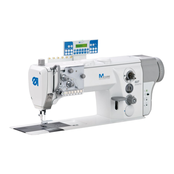
(2) - Adjusting wheel maintenance unit for roller top feed (6) - Control (3) - Thread tension plate (7) - Adjusting wheel for (4) - Pedal the stitch length (8) - Winder (9) - Reel stand Operating Instructions 827/827-M - 01.0 - 02/2019... - Page 18 Machine description Fig. 2: Components of the machine (2) ⑩ (10) - Roller top feed Operating Instructions 827/827-M - 01.0 - 02/2019...
-
Page 19: Proper Use
DIN EN 60204-31. Only authorized persons may work on the machine. Dürkopp Adler cannot be held liable for damages resulting from improper use. Operating Instructions 827/827-M - 01.0 - 02/2019... -
Page 20: Declaration Of Conformity
Machine description Declaration of Conformity The machine complies with European regulations ensuring health, safety, and environmental protection as specified in the declara- tion of conformity or in the declaration of incorporation. Operating Instructions 827/827-M - 01.0 - 02/2019... -
Page 21: Operation
Complete the following steps in preparation of sewing before starting to work: • Inserting/changing the needle • Threading the needle thread • Inserting and winding on the hook thread • Setting the thread tension Operating Instructions 827/827-M - 01.0 - 02/2019... -
Page 22: Switching On And Off The Machine
The machine and the control panel start up. Switching off the machine To switch off the machine: Press the main switch (1) from position I to position 0. The machine and the control panel shut down. Operating Instructions 827/827-M - 01.0 - 02/2019... -
Page 23: Inserting/Changing The Needle
Pull the needle straight downwards out of the needle bar (3). Insert the new needle straight into the needle bar (3) until it reaches the end stop. Important The groove (1) for the needle must face the hook. Tighten the screw (2). Operating Instructions 827/827-M - 01.0 - 02/2019... -
Page 24: Threading The Needle Thread
Insert the needle thread through the guide (13). Insert the needle thread in a wavelike manner from top to bottom through the guide (12), as shown above. Guide the needle thread clockwise through the pre-tensioner (11). Operating Instructions 827/827-M - 01.0 - 02/2019... - Page 25 12. Feed the needle thread through guides (4) and (5). 13. Feed the needle thread through the guide (6) on the needle bar. 14. Feed the needle thread through the needle eye from left to right. Operating Instructions 827/827-M - 01.0 - 02/2019...
-
Page 26: Needle Thread Threading On 2-Needle Machines
Feed the needle thread from the right to the left through the thread tension spring (7). The remaining steps of the threading process are identical to the threading process in 1-needle machines. Operating Instructions 827/827-M - 01.0 - 02/2019... -
Page 27: Winding The Hook Thread
Insert the hook thread in a wavelike manner from top to bottom through the guide (2), as shown above. Feed the hook thread counterclockwise through the tensioner (3). Feed the hook thread from bottom to top through the guide (7). Operating Instructions 827/827-M - 01.0 - 02/2019... - Page 28 The winder always stops such that the thread-pulling knife (6) is at the proper position. 10. Pull off the full bobbin. 11. Clamp the hook thread behind the thread-pulling knife (6) and tear it off. Operating Instructions 827/827-M - 01.0 - 02/2019...
-
Page 29: Changing The Bobbin
Insert the bobbin so that it moves in the opposite direction of the hook when the thread is pulled out. Feed the hook thread through the slot (4) in the bobbin case retainer. Operating Instructions 827/827-M - 01.0 - 02/2019... -
Page 30: Thread Tension
Fig. 9: Thread tension ① ② ③ (1) - Identical needle thread and hook thread tension (2) - Hook thread tension higher than needle thread tension (3) - Needle thread tension higher than hook thread tension Operating Instructions 827/827-M - 01.0 - 02/2019... -
Page 31: Setting The Needle Thread Tension
Turn the pre-tensioner adjusting wheel (2) until the front side is flush with the bolt (1). • Shorter initial thread: Turn the adjusting wheel (2) clock- wise • Longer initial thread: Turn the adjusting wheel (2) counter- clockwise Operating Instructions 827/827-M - 01.0 - 02/2019... - Page 32 The additional tensioner (4) should always be set lower than the main tensioner (3). To set the additional tensioner: Turn the adjusting wheel (4). • Increase the tension: turn clockwise • Reduce the tension: turn counterclockwise Operating Instructions 827/827-M - 01.0 - 02/2019...
-
Page 33: Setting The Hook Thread Tension
The hook thread tension is generated by the tension spring (1) and adjusted via the screw (2). To set the hook thread tension: Turn the screw (2). • Increase the hook thread tension: turn clockwise • Reduce the hook thread tension: turn counterclockwise Operating Instructions 827/827-M - 01.0 - 02/2019... -
Page 34: Sewing Foot
Press the pedal (1) halfway back. The sewing foot is lifted during a machine standstill. Press the pedal (1) fully back. The thread cutter is activated, and the sewing foot is lifted. Operating Instructions 827/827-M - 01.0 - 02/2019... -
Page 35: Locking The Sewing Foot In Top Dead Center
Removing the lock To remove the lock: Swivel the lever (1) up. The lock is canceled. Press the pedal. The lock is canceled, and the lever (1) swivels back to its initial position. Operating Instructions 827/827-M - 01.0 - 02/2019... -
Page 36: Setting The Sewing Foot Pressure
Fig. 14: Setting the sewing foot pressure ① (1) - Adjusting wheel To set the sewing foot pressure: Turn the adjusting wheel (1). • Increase sewing foot pressure: turn clockwise • Reduce sewing foot pressure: turn counterclockwise Operating Instructions 827/827-M - 01.0 - 02/2019... -
Page 37: Setting The Stitch Length
Fig. 15: Setting the stitch length ① (1) - Adjusting wheel for the stitch length To set the stitch length: Turn the adjusting wheel (1). • Minimum stitch length: 1 • Maximum stitch length: 7 Operating Instructions 827/827-M - 01.0 - 02/2019... -
Page 38: Roller Top Feed
Switching on the roller top feed To switch on the roller top feed: Push the lever (1) down. The carrier roller (2) descends onto the sewing material. Operating Instructions 827/827-M - 01.0 - 02/2019... - Page 39 The roller carrier is lowered during the completion of the subsequent seams. To deactivate the roller top feed: Press the button (1). The button turns off. The roller top feed is switched off. Operating Instructions 827/827-M - 01.0 - 02/2019...
-
Page 40: Buttons On The Machine Arm
(3) - Start and end bartacks (2) - Needle position (4) - Roller top feed To activate a button on the machine arm: Press the button. The function is activated. The button lights up. Operating Instructions 827/827-M - 01.0 - 02/2019... - Page 41 For the general setting of start and end bartacks, see Instructions for use of the DACclassic control. Roller top feed If the button is selected, the roller top feed is activated ( p. 36) Operating Instructions 827/827-M - 01.0 - 02/2019...
-
Page 42: Transferring A Button Function To The Favorite Button
Bring all screws (4) to their initial position (2): all slots are horizontal. Turn the screw under the desired button 90° so that the slot is vertical (3). The function of the selected button can be activated using the favorite button (1). Operating Instructions 827/827-M - 01.0 - 02/2019... -
Page 43: Sewing
Machine stationary, needles up, sewing feet down. Positioning the sewing material To position the sewing material: Press the pedal halfway back in pedal position -1. The sewing feet are lifted. Push the sewing material into the initial position. Operating Instructions 827/827-M - 01.0 - 02/2019... - Page 44 Press the pedal back completely in pedal position -2. The machine sews the end bartack, and the thread cutter cuts the thread. The machine stops, needles and sewing feet are up. Remove the sewing material. Operating Instructions 827/827-M - 01.0 - 02/2019...
-
Page 45: Programming
(1) - Power LED (5) - Seam program button group (2) - Thread button group (6) - LED for 2 Stitch length (3) - Function button (7) - Display (4) - Programming button group Operating Instructions 827/827-M - 01.0 - 02/2019... - Page 46 Sewing foot lift after • Activates or deactivates sewing stop the sewing foot lift after sewing stops Soft start • Activates or deactivates the soft start Operating Instructions 827/827-M - 01.0 - 02/2019...
- Page 47 • Changes to next higher category • Selects subprogram • Increases parameter • Selects subprogram • Increases parameter • Selects subprogram • Calls parameter or saves it • Starts or ends the param- eter mode Operating Instructions 827/827-M - 01.0 - 02/2019...
- Page 48 • Selects subprogram • Decreases parameter • Changes to next lower category • Selects subprogram • Decreases parameter • Selects subprogram • Decreases parameter • Selects subprogram Reset • Resets the (piece) counter Operating Instructions 827/827-M - 01.0 - 02/2019...
- Page 49 Programming Button Function Seam program button group Seam program I • Activates seam program I Seam program II • Activates seam program II Seam program III • Sets seam program III Operating Instructions 827/827-M - 01.0 - 02/2019...
-
Page 50: Setting The Electropneumatic Switching Of The Carrier Roller
• Use D+ to enter the value 3: raise on bartack and sewing foot lift To save the settings, press the button. To switch to sewing mode, press the button. For additional parameter settings, refer to Parameter list. Operating Instructions 827/827-M - 01.0 - 02/2019... -
Page 51: Setting The Stitch Count Before Carrier Roller Is Lowered
Use the buttons A+, B+, C+ and D+ to enter the desired number of stitches. To save the settings, press the button. To switch to sewing mode, press the button. For additional parameter settings, refer to Parameter list. Operating Instructions 827/827-M - 01.0 - 02/2019... - Page 52 Programming Operating Instructions 827/827-M - 01.0 - 02/2019...
-
Page 53: Maintenance
Advanced maintenance work may only be carried out by qualified specialists ( Service Instructions). Operating Instructions 827/827-M - 01.0 - 02/2019... - Page 54 Removing lint and thread remnants Motor fan filter Lubricating Machine head Hook Pneumatic system Check the operating pressure Check the water level in the pressure controller Cleaning the filter element Operating Instructions 827/827-M - 01.0 - 02/2019...
-
Page 55: Cleaning
Lint and thread remnants can impair the operation of the machine. Clean the machine as described. NOTICE Property damage from solvent-based cleaners! Solvent-based cleaners will damage paintwork. Use only solvent-free substances for cleaning. Operating Instructions 827/827-M - 01.0 - 02/2019... -
Page 56: Cleaning The Machine Head
Points that need to be cleaned particularly thoroughly: • Cutter on the winder for the hook thread (4) • Area under the throat plate (3) • Hook (2) • Area around the needle (1) Operating Instructions 827/827-M - 01.0 - 02/2019... -
Page 57: Cleaning The Direct Drive
To clean the direct drive: Remove the hand wheel (2). Blow out the net in the hand wheel (2) and the motor shaft (1) with the compressed air gun. Put the hand wheel (2) back on. Operating Instructions 827/827-M - 01.0 - 02/2019... -
Page 58: Lubricating
The bearings are supplied from the oil reservoir. For topping off the oil reservoir, use only lubricating oil DA 10 or oil of equivalent quality with the following specifications: • Viscosity at 40 °C:10 mm • Flash point: 150 °C Operating Instructions 827/827-M - 01.0 - 02/2019... -
Page 59: Lubricating The Machine Head
The oil level must not rise above the maximum level marking (2) or drop below the minimum level marking (3). To lubricate the machine head: Fill oil through the filler opening (1) no higher than the maxi- mum level marking (2). Operating Instructions 827/827-M - 01.0 - 02/2019... -
Page 60: Lubricating The Hook
• clockwise: less oil is released Important The released amount of oil does not change until the operating time has run a few minutes. Sew for several minutes before you check the setting again. Operating Instructions 827/827-M - 01.0 - 02/2019... -
Page 61: Servicing The Pneumatic System
Check the operating pressure on a daily basis. Fig. 26: Setting the operating pressure ① ② (1) - Pressure controller (2) - Pressure gage To set the operating pressure: Pull the pressure controller (1) up. Operating Instructions 827/827-M - 01.0 - 02/2019... -
Page 62: Draining The Water Condensation
Water condensation accumulates in the water separator (2) of the pressure controller. Proper setting Water condensation must not rise up to the level of the filter element (1). Check the water level in the water separator (2) on a daily basis. Operating Instructions 827/827-M - 01.0 - 02/2019... - Page 63 Place the collection tray under the drain screw (3). Loosen the drain screw (3) completely. Allow water to drain into the collection tray. Tighten the drain screw (3). Connect the machine to the compressed air supply. Operating Instructions 827/827-M - 01.0 - 02/2019...
-
Page 64: Cleaning The Filter Element
Loosen the filter element (1). Blow out the filter element (1) using a compressed air gun. Wash out the filter tray using benzine. Tighten the filter element (1). Tighten the water separator (2). Operating Instructions 827/827-M - 01.0 - 02/2019... -
Page 65: Parts List
Tighten the drain screw (3). 10. Connect the machine to the compressed air supply. Parts list A parts list can be ordered from Dürkopp Adler. Or visit our website for further information at: www.duerkopp-adler.com Operating Instructions 827/827-M - 01.0 - 02/2019... - Page 66 Maintenance Operating Instructions 827/827-M - 01.0 - 02/2019...
-
Page 67: Setup
• Lashing straps and wooden blocks from the machine head • Lashing straps and wooden blocks from the tabletop • Lashing straps and wooden blocks from the stand • Restrain block and lashing straps from the sewing drive Operating Instructions 827/827-M - 01.0 - 02/2019... -
Page 68: Assembling The Stand
( p. 68) Tighten the oil can holder (1). Turn the adjusting screw (4) to ensure that the stand is positioned securely. All 4 feet of the stand must be in contact with the floor. Operating Instructions 827/827-M - 01.0 - 02/2019... -
Page 69: Tabletop
Flip the tabletop (8) over. Tighten the cable duct (7). Tighten the power supply (5). Tighten the knee button (4). Tighten the setpoint device (3). Tighten the drawer (2) and brackets. Tighten the sewing lamp transformer (1). Operating Instructions 827/827-M - 01.0 - 02/2019... -
Page 70: Making Your Own Tabletop
Fig. 31: Assembling the tabletop and the pedal to the stand ① ⑦ ⑥ ② ③ ④ ⑤ (1) - Tabletop (5) - Cross strut (2) - Stand (6) - Rod (3) - Screw (7) - Reel stand (4) - Pedal Operating Instructions 827/827-M - 01.0 - 02/2019... - Page 71 Insert the reel stand (7) into the hole in the tabletop (1) and secure it with a nut and washer. 10. Align thread reel holder and thread guide. Important The thread guide must be positioned vertically above the thread reel holder. Operating Instructions 827/827-M - 01.0 - 02/2019...
-
Page 72: Setting The Working Height
Risk of musculoskeletal damage from incorrect setting! The operator can sustain musculoskeletal damage if failing to comply with the ergonomic requirements. Adjust the working height to the body height of the person who will operate the machine. Operating Instructions 827/827-M - 01.0 - 02/2019... - Page 73 Tighten the screws (1). Set the length of the pedal rod. Set the height of the pedal rod so that the slope of the released pedal is approx. 10°. Operating Instructions 827/827-M - 01.0 - 02/2019...
-
Page 74: Inserting The Machine Head
To insert the machine head: Insert the machine head (1) into the tabletop cutout (2) at a 45° angle. Insert the upper hinge parts (4) into the rubber inlays (3). Tilt the machine head. Operating Instructions 827/827-M - 01.0 - 02/2019... -
Page 75: Assembling The Control Panel
To assemble the control panel: Tighten the control panel (1) to the bracket (3) using the screw (2). Tighten the bracket (3) to the machine arm using the screws (5). Remove the valve cover (4). Operating Instructions 827/827-M - 01.0 - 02/2019... - Page 76 Install the control panel cable (7) in the machine arm and feed it downwards through the tabletop cutout (6). Insert the plug of the control panel cable (7) into socket B776 of the control. Place the valve cover (4). Operating Instructions 827/827-M - 01.0 - 02/2019...
-
Page 77: Assembling The Electric Knee Button
Guide the connecting cable (2) to the back between the oil pan and the control. Insert the plug (3) of the connecting cable (2) into the socket of the control. Operating Instructions 827/827-M - 01.0 - 02/2019... -
Page 78: Assembling The Sewing Lamp
Drill the mounting holes (4) using a drill (Ø 4.5 mm). Tighten the retainer plate (5) using the screws (3). Place the arm cover. Assemble the sewing lamp (2) to the retainer plate (5). Operating Instructions 827/827-M - 01.0 - 02/2019... -
Page 79: Electrical Connection
(1) - Tab connector (3) - Screw (2) - Grounding wire To establish equipotential bonding at the machine head: Slip the grounding wire (2) onto the tab connector (1) on the machine head. Operating Instructions 827/827-M - 01.0 - 02/2019... - Page 80 To establish equipotential bonding at the knee button: Assemble the large eye of the grounding wire (3) to the knee button using the screw (2). Tighten the grounding wire (3) to the control using the screw (1). Operating Instructions 827/827-M - 01.0 - 02/2019...
-
Page 81: Connecting The Control
Setup 7.10.2 Connecting the control Fig. 40: Connecting the control To connect the control: Connect the cables to the control. The cables and the correct plugs are each marked with a symbol. Operating Instructions 827/827-M - 01.0 - 02/2019... -
Page 82: Connecting The Knee Button
To connect the knee button: Connect the grounding connection of the knee button to the rear of the control (1). Insert the plug of the knee button into the connecting socket of the control. Operating Instructions 827/827-M - 01.0 - 02/2019... -
Page 83: Assembling And Connecting The Sewing Lamp Transformer (Optional)
Connect the electrical connection cable (4) on the electrical connection side of the main switch as specified in the wiring diagram ( p. 105). Apply the adhesive label (3) on the front side of the sewing lamp transformer (2). Operating Instructions 827/827-M - 01.0 - 02/2019... - Page 84 12. Press a narrow screwdriver into terminal openings (7) or (8) to open terminals (6) and (5). 13. Connect the blue cable to the terminal (5). 14. Connect the brown cable to the terminal (6). 15. Assemble the front panel again. Operating Instructions 827/827-M - 01.0 - 02/2019...
-
Page 85: Connecting The Sewing Lamp To The Sewing Lamp Transformer
Fig. 45: Connecting the sewing lamp to the sewing lamp transformer (2) ② (4) - Sewing lamp transformer Guide the cable (3) with cable clamps under the tabletop. Connect the cable (3) with the sewing lamp transformer (4). Operating Instructions 827/827-M - 01.0 - 02/2019... -
Page 86: Pneumatic Connection
7.11.1 Assembling the compressed air maintenance unit To assemble the compressed air maintenance unit: Connect the connection hose to the compressed air supply using a hose coupling R 1/4”. Operating Instructions 827/827-M - 01.0 - 02/2019... -
Page 87: Setting The Operating Pressure
The operating pressure cannot deviate by more than ± 0.5 bar. Fig. 46: Setting the operating pressure ① ② (1) - Pressure controller (2) - Pressure gage To set the operating pressure: Pull the pressure controller (1) up. Operating Instructions 827/827-M - 01.0 - 02/2019... -
Page 88: Performing A Test Run
• Reduce pressure = turn counterclockwise Push the pressure controller (1) down. 7.12 Performing a test run When setup is complete, perform a test run to check the function- ality of the machine. Operating Instructions 827/827-M - 01.0 - 02/2019... -
Page 89: Decommissioning
Remove residual oil from the oil pan using a cloth. Cover the control panel to protect it from soiling. Cover the control to protect it from soiling. Cover the entire machine if possible to protect it from contam- ination and damage. Operating Instructions 827/827-M - 01.0 - 02/2019... - Page 90 Decommissioning Operating Instructions 827/827-M - 01.0 - 02/2019...
-
Page 91: Disposal
When disposing of the machine, be aware that it consists of a range of different materials (steel, plastic, electronic components, etc.). Follow the national regulations when disposing these materials. Operating Instructions 827/827-M - 01.0 - 02/2019... - Page 92 Disposal Operating Instructions 827/827-M - 01.0 - 02/2019...
-
Page 93: Troubleshooting
Contact for repairs and issues with the machine: Dürkopp Adler AG Potsdamer Str. 190 33719 Bielefeld, Germany Tel. +49 (0) 180 5 383 756 Fax +49 (0) 521 925 2594 Email: service@duerkopp-adler.com Internet: www.duerkopp-adler.com Operating Instructions 827/827-M - 01.0 - 02/2019... -
Page 94: Messages Of The Software
• Check connection cables position not found • Check stepper motor 1 for stiff movement 2220 DA stepper card 2 not • Check connection cables responding • Check LEDs of DACextension • Perform software update Operating Instructions 827/827-M - 01.0 - 02/2019... - Page 95 • Change bobbin, set counter (info value 0 reached) value, press counter reset button 3216 Remaining thread monitor • Change the left bobbin left 3217 Remaining thread monitor • Change the right bobbin right Operating Instructions 827/827-M - 01.0 - 02/2019...
- Page 96 6365 Internal EEprom defective • Replace the control 6366 Internal EEprom defective • Replace the control and external data not valid (emergency operating features only) Operating Instructions 827/827-M - 01.0 - 02/2019...
- Page 97 DAC basic will remain available) 7803 Communication error (DAC • Restart the control classic only; only the • Perform software update functions of the DAC basic • Replace the control will remain available) Operating Instructions 827/827-M - 01.0 - 02/2019...
-
Page 98: Error Messages
• Perform reset • Check class (parameter t 51 04) 1007 Error in the reference run • Replace the encoder • Eliminate stiff movement in the machine 1008 Encoder error • Replace the encoder Operating Instructions 827/827-M - 01.0 - 02/2019... - Page 99 DA stepper card 2 reference • Check reference sensor run timeout 2203 DA stepper card 2 step • Check machine for stiff losses movement 2255 DA stepper card 2 overload • Check machine for stiff movement Operating Instructions 827/827-M - 01.0 - 02/2019...
- Page 100 • Switch off the control, wait until communication error the LEDs are off, check connection for machine ID, and switch on control again 8401 Watchdog • Perform software update • Perform a machine ID reset • Replace the control Operating Instructions 827/827-M - 01.0 - 02/2019...
- Page 101 • Perform a machine ID reset • Replace the control 8406 Checksum error • Perform software update • Replace the control 8501 Software protection • The DA tool must always be used for software updates Operating Instructions 827/827-M - 01.0 - 02/2019...
-
Page 102: Errors In Sewing Process
Thread-guiding parts, such Check threading path as thread tube, thread guide or thread take-up disk, are sharp-edged Throat plate, hook or Have parts reworked by spread have been qualified specialists damaged by the needle Operating Instructions 827/827-M - 01.0 - 02/2019... - Page 103 Needle thread and hook Check threading path thread have not been threaded correctly Needle Needle thickness is Use recommended needle breakage unsuitable for the sewing thickness material or the thread Operating Instructions 827/827-M - 01.0 - 02/2019...
- Page 104 Troubleshooting Operating Instructions 827/827-M - 01.0 - 02/2019...
- Page 105 [Nm] 20/3 Stitch length [mm] Speed maximum 3800 [min Speed on delivery 3400 [min Mains voltage Mains frequency [Hz] 50 - 60 Operating pressure [bar] Length [mm] Width [mm] Height [mm] Weight [kg] Operating Instructions 827/827-M - 01.0 - 02/2019...
- Page 106 • Automatic wick lubrication with inspection glasses for oil level indication • Large vertical hook with CTB bobbins • Safety snap-on coupling prevents any misadjustment or dam- age to the hook in the event of a thread jamming Operating Instructions 827/827-M - 01.0 - 02/2019...
- Page 107 Appendix 12 Appendix Tabletop drawings Operating Instructions 827/827-M - 01.0 - 02/2019...
- Page 108 Appendix Operating Instructions 827/827-M - 01.0 - 02/2019...
- Page 110 Potsdamer Straße 190 33719 Bielefeld GERMANY Phone +49 (0) 521 / 925-00 E-mail @duerkopp-adler.com www.duerkopp-adler.com...
Need help?
Do you have a question about the 827-M and is the answer not in the manual?
Questions and answers