
Related Manuals for Danfoss ADAP-KOOL AK-LM 340


Summary of Contents for Danfoss ADAP-KOOL AK-LM 340
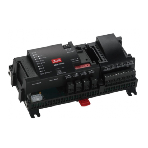
- Page 1 User Guide Monitoring unit with PI regulation AK-LM 340 ADAP-KOOL® Refrigeration control systems...
-
Page 2: Table Of Contents
First start of control ................77 Determine the connection points ..........39 Start the control ................78 Connection diagram ..............40 Setup logs ..................79 Supply voltage .................41 5. Regulating functions .............81 Ordering .....................42 Monitoring functions ................82 Miscellaneous ..................88 Alarm texts ....................90 RS8GV202 © Danfoss 2016-06 AK-LM 340... -
Page 3: Introduction
• Two alarm relays that are enabled on different alarm priorities PI regulations • 10 separate functions can be constructed. Data communication • Connection to system manager or gateway • Monitoring and data collection • Customised alarm texts SW = 1.1x AK-LM 340 RS8GV202 © Danfoss 2016-06... -
Page 4: Principles
• In addition to the software the top part is provided with connections for data communication and address setting. A regulation with few connections can If there are many connections one or more Examples be performed with the controller module extension modules have to be mounted alone RS8GV202 © Danfoss 2016-06 AK-LM 340... - Page 5 All users must be assigned a user profile which either gives access to full operation or gradually limits the operation to the lowest level that only allows you “to see”. AK-LM 340 RS8GV202 © Danfoss 2016-06...
- Page 6 If you want to know more about a current alarm you can click on it and obtain an information display on the screen. A corresponding display exists for all earlier alarms. Here you can upload information if you need further details about the alarm history. RS8GV202 © Danfoss 2016-06 AK-LM 340...
-
Page 7: Design Of A Controller
If it is an application with many connections it will be necessary to use the controller module plus one or more extension modules. This section will give you a survey of possible connections plus assistance in selecting the modules required by your actual application. AK-LM 340 RS8GV202 © Danfoss 2016-06... -
Page 8: Module Survey
Controller with analog inputs and relay outputs. Top part The module with additional relay outputs is also available in a version where the top part is provided with change-over switches so that the relays can be overridden. RS8GV202 © Danfoss 2016-06 AK-LM 340... - Page 9 To be mounted in an AK controller Accessories Communication modules for controllers where modules cannot be connected continuously AK-CM 102 Communication module Data communication for external extension modules On the following pages there is data specific to each module. AK-LM 340 RS8GV202 © Danfoss 2016-06...
-
Page 10: Common Data For Modules
The relays cannot be used for the direct connection of capacitive loads such as LEDs and on/off control of EC motors. All loads with a switch mode power supply must be connected with a suitable con- tactor or similar. RS8GV202 © Danfoss 2016-06 AK-LM 340... - Page 11 The module dimension is 72 mm. Modules in the 100-series consist of one module Modules in the 200-series consist of two modules Controllers consist of three modules The length of an aggregate unit = n x 72 + 8 AK-LM 340 RS8GV202 © Danfoss 2016-06...
-
Page 12: Controller
• Software status (slow flash = OK) • Communication with Service Tool • Communication on LON • Communication with AK-CM 102 • Alarm when LED flashes - 2 LED’s that are not used • “Service Pin” switch has been activated RS8GV202 © Danfoss 2016-06 AK-LM 340... - Page 13 15 (DO 4) 37 - 38 16 (DO 5) 39 - 40- 41 17 (DO6) 42 - 43 - 44 18 (DO7) 45 - 46 - 47 19 (DO8) 48 - 49 - 50 AK-LM 340 RS8GV202 © Danfoss 2016-06...
-
Page 14: Extension Module Ak-Xm 101A
5 V output or the 12 V output depending on transmitter type. Light-emitting diodes Only the two top LED’s are used. They indicate the following: • Voltage supply to the module • Communication with the controller is active (red = error) RS8GV202 © Danfoss 2016-06 AK-LM 340... - Page 15 7 - 8 Active at: Day/ Night 5 (AI 5) 17 - 18 Closed Door 6 (AI 6) 19 - 20 Open Defrost 7 (AI 7) 21 - 22 8 (AI 8) 23 - 24 AK-LM 340 RS8GV202 © Danfoss 2016-06...
-
Page 16: Extension Module Ak-Xm 102A / Ak-Xm 102B
• Communication with the controller is active (red = error) Off: DI < 2 V a.c. Off: DI < 24 V a.c. • Status of the individual inputs 1 to 8 (when lit = voltage) RS8GV202 © Danfoss 2016-06 AK-LM 340... - Page 17 3 (DI 3) 5 - 6 4 (DI 4) 7 - 8 5 (DI 5) 9 - 10 6 (DI 6) 11 - 12 7 (DI 7) 13 - 14 8 (DI 8) 15 - 16 AK-LM 340 RS8GV202 © Danfoss 2016-06...
-
Page 18: Extension Module Ak-Xm 103A
Only the two top LED’s are used. They indicate the following: • Voltage supply to the module • Communication with the controller is active (red = error) Max. load I < 2.5 mA R > 4 kΩ RS8GV202 © Danfoss 2016-06 AK-LM 340... - Page 19 Active at: 5 (AO 1) 17 - 18 Day/ Night Closed 6 (AO 2) 19 - 20 Door Open 7 (AO 3) 21 - 22 Level switch 8 (AO 4) 23 - 24 0-10 V AK-LM 340 RS8GV202 © Danfoss 2016-06...
-
Page 20: Extension Module Ak-Xm 204A / Ak-Xm 204B
Behind the upper part there is a fuse for each output. AC-1: max. 4 A (ohmic) must not be connected to the same output group AC-15: max. 3 A (Inductive) AK-XM 204B Override of relay RS8GV202 © Danfoss 2016-06 AK-LM 340... - Page 21 34 - 35 -36 5 (DO 5) 37 - 38 - 39 6 (DO 6) 40 - 41 - 42 7 (DO 7) 43 - 44 - 45 8 (DO 8) 46 - 47 - 48 AK-LM 340 RS8GV202 © Danfoss 2016-06...
-
Page 22: Extension Module Ak-Xm 205A / Ak-Xm 205B
AC-1: max. 4 A (ohmic) Behind the upper part there is a fuse for each output. must not be connected to AC-15: max. 3 A (Inductive) the same output group AK-XM 205B Override of relay RS8GV202 © Danfoss 2016-06 AK-LM 340... - Page 23 13 (DO 5) 37 - 36 - 39 Defrost Night 14 (DO6) 40 - 41 - 42 blinds Valves 15 (DO7) 43 - 44 - 45 Compres- sors 16 (DO8) 46 - 47 - 48 AK-LM 340 RS8GV202 © Danfoss 2016-06...
-
Page 24: Extension Module Ak-Xm 107A
(There is no LED indication for the individual signal inputs) Signal The signal is registered in accordance with DIN 43864. Rise times and fall times must be less than 5 ms. On and off times must be greater than 30 ms. RS8GV202 © Danfoss 2016-06 AK-LM 340... - Page 25 5 (CI 5) 9 - 10 - - - 6 (CI 6) 11 - 12 - - - 7 (CI 7) 13 - 14 - - - 8 (CI 8) 15 - 16 - - - AK-LM 340 RS8GV202 © Danfoss 2016-06...
-
Page 26: Extension Module Ak-Xm 208C
• Voltage supply to the module • Communication active with the bottom PC board (red = error) • Status of outputs AO1 to AO4 Output: 24 V d.c. = 500 m A / coil max. 20-500 step/s RS8GV202 © Danfoss 2016-06 AK-LM 340... - Page 27 KVS 15 White Black Green KVS 42-54 Valve Module Step Terminal 1 (point 9) 25 - 28 2 (point 10) 29 - 32 3 (point 11) 33 - 36 4 (point 12) 37 - 40 AK-LM 340 RS8GV202 © Danfoss 2016-06...
-
Page 28: Extension Module Ak-Ob 110
The two outputs have points 24 and 25. They are shown on the earlier page where the controller is also mentioned. Max. load I < 2.5 mA R > 4 kohm Module Point 0 - 10 V Type RS8GV202 © Danfoss 2016-06 AK-LM 340... -
Page 29: Extension Module Ak-Ob 101A
The working life of the battery is several years – even if there are frequent power failures. An alarm is generated when the battery has to be replaced. After the alarm there are still several months of operating hours left in the battery. AK-LM 340 RS8GV202 © Danfoss 2016-06... -
Page 30: Communication Module Ak-Cm 102
The controller should permanently be set to = ON. Warning Additional modules may only be installed following the installa- tion of the final module. (Here following module no. 11; see the sketch.) After configuration, the address must not be changed. RS8GV202 © Danfoss 2016-06 AK-LM 340... -
Page 31: Transformer Module Ak-Ps 075 / 150
AK-PS 150 24 V d.c. 1.5 A 36 VA Dimension Connections Type High Width AK-PS 075 90 mm 36 mm AK-PS 150 90 mm 54 mm Supply to a controller AK-PS 075 AK-PS 150 AK-LM 340 RS8GV202 © Danfoss 2016-06... -
Page 32: Preface To Design
Regulation can be started and stopped via the software. document. Literature no. RC8AC. Alarm function If the alarm is to be sent to a signal transmitter, a relay output will have to be used. RS8GV202 © Danfoss 2016-06 AK-LM 340... -
Page 33: Connections
(If one controller is switched off, the sig- nal will be pulled down, and all the other controllers will receive a signal which is too low) AK-LM 340 RS8GV202 © Danfoss 2016-06... -
Page 34: Design Of A Monitoring
9. The modules are linked together 10. The connection sites are established 11. Draw a connection diagram or a key diagram 12. Size of supply voltage/transformer Sketch Make a sketch of the system in question. RS8GV202 © Danfoss 2016-06 AK-LM 340... -
Page 35: Monitoring Unit
Read out of the consumption during the last week Read out of the total consumption since the last reset Alarm relay Number Priority "high" or priority "low to high" Miscellaneous Alarm priorities Sensor correction AK-LM 340 RS8GV202 © Danfoss 2016-06... -
Page 36: Connections
• Difference pressostat • Two sensor thermostat Data from this example is used on the next page. The result is that the following modules should be used: • AK-LM 340 Monitoring unit • No extension modules RS8GV202 © Danfoss 2016-06 AK-LM 340... -
Page 37: Planning Table
AK-XM 208C (8 analog inputs + 4 stepper outputs) ___ pcs. á 5 VA = __ AK_OB 110 (2 analog outputs) ___ pcs. á 0 VA = __ 1 pcs. á 8 VA = 8 Sum = Sum = max. 32 VA AK-LM 340 RS8GV202 © Danfoss 2016-06... -
Page 38: Length
DIN rail – no matter where in the row the module is found. Removal is likewise carried out with the two catches in the open position. RS8GV202 © Danfoss 2016-06 AK-LM 340... -
Page 39: Determine The Connection Points
15 (DO 4) 37 - 38 16 (DO 5) 39-40-41 Relay for valve 17 (DO6) 42-43-44 Relay for pump A. 18 (DO7) 45-46-47 (Difference pressostat) Relay for pump B 19 (DO8) 48-49-50 (Two sensor thermostat) AK-LM 340 RS8GV202 © Danfoss 2016-06... -
Page 40: Connection Diagram
Connection diagram Drawings of the individual modules may be ordered from Danfoss. Format = dwg and dxf. You may then yourself write the module number in the circle and draw the individual connections. Example continued: RS8GV202 © Danfoss 2016-06 AK-LM 340... -
Page 41: Supply Voltage
(If one controller is switched off, the sig- nal will be pulled down, and all the other controllers will receive a signal which is too low) Example continued: Controller module 8 VA ------ Power supply size (least) 8 VA AK-LM 340 RS8GV202 © Danfoss 2016-06... -
Page 42: Ordering
Real time clock with battery backup. To be mounted in an AK controller 080Z0252 Accessories Communication modules for controllers where modules cannot be connected continuously AK-CM 102 Communication module Data communication for external extension modules 080Z0064 RS8GV202 © Danfoss 2016-06 AK-LM 340... -
Page 43: Mounting And Wiring
This section describes how the controller: • Is fitted • Is connected We have decided to work on the basis of the example we went through previously, i.e. the following modules: • AK-LM 340 Monitoring unit AK-LM 340 RS8GV202 © Danfoss 2016-06... -
Page 44: Mounting
DIN rail – regard- less of where the module is on the row. Disassembly is thus done with the two snap catches in the open posi- tion. RS8GV202 © Danfoss 2016-06 AK-LM 340... -
Page 45: Wiring
15 (DO 4) 37 - 38 16 (DO 5) 39-40-41 Relay for valve 17 (DO6) 42-43-44 Relay for pump A. 18 (DO7) 45-46-47 (Difference pressostat) Relay for pump B 19 (DO8) 48-49-50 (Two sensor thermostat) AK-LM 340 RS8GV202 © Danfoss 2016-06... - Page 46 Network installation When the controller is set correct on the network the LED "sta- tus" will flash quickly for 10 minutes. Status on output 1-8 6. The controller is now ready to be configured. RS8GV202 © Danfoss 2016-06 AK-LM 340...
-
Page 47: Configuration And Operation
• Is configured • Is operated We have decided to work on the basis of the example we went through previously, i.e. • Difference thermostat, • Difference pressostat • Two-sensor thermostat. The example is shown overleaf. AK-LM 340 RS8GV202 © Danfoss 2016-06... - Page 48 The example is the same as the one given in the "Design" section, i.e. the controller is an AK-LM 340. Three separate controls: • Difference thermostat • Difference pressostat • Two-sensor thermostat RS8GV202 © Danfoss 2016-06 AK-LM 340...
-
Page 49: Configuration
The red alarm bell at the bottom right tells you that there is an active alarm in the controller. In our case the alarm is due to the fact that the time in the controller has not yet been set. AK-LM 340 RS8GV202 © Danfoss 2016-06... -
Page 50: Authorization
SUPV and the the new access code relevant access code. You will access the login display by pressing the icon at the top left corner of the display. RS8GV202 © Danfoss 2016-06 AK-LM 340... -
Page 51: Unlock The Configuration Of The Controllers
On. Only when the main switch is set to Off, and regulation has therefore been stopped, is it possible to set the configuration lock. 4. Select Unlocked Select Unlocked AK-LM 340 RS8GV202 © Danfoss 2016-06... -
Page 52: System Setup
When the controller is connected to a net- work, date and time will automatically be set by the system unit in the network. This also applies to change-over Daylight saving. RS8GV202 © Danfoss 2016-06 AK-LM 340... -
Page 53: Set Plant Type
If an alarm relay is defined, it will activate an alarm that must be reset externally. Quick setup The function is reserved for a later, quick setup sequence. It also contains a “return to factory settings” function. AK-LM 340 RS8GV202 © Danfoss 2016-06... -
Page 54: Utility Meters
These display the total consumption, the current load and the average load over the period of time. 3. Utility meter We have not used this function in our example. The image is included for guidance only. RS8GV202 © Danfoss 2016-06 AK-LM 340... -
Page 55: Thermostat Functions
• Alarm text high Indicate alarm text for the high alarm • Low alarm limit Low alarm limit • Alarm delay low Time delay for low alarm • Alarm text low Indicate alarm text for low alarm AK-LM 340 RS8GV202 © Danfoss 2016-06... -
Page 56: Two Sensor Thermostat
3. Two sensor thermostat • DI -input for stop of function The regulation stops immediately when a signal is received. Delay time will not be considered. In our example we use the settings shown. RS8GV202 © Danfoss 2016-06 AK-LM 340... -
Page 57: Difference Thermostat
Low alarm limit • In our example we use the settings shown. ow alarm limit Alarm delay low • Time delay for low alarm • Alarm text low Indicate alarm text for low alarm AK-LM 340 RS8GV202 © Danfoss 2016-06... -
Page 58: Temperature Alarms
Here a DI signal can be selected, which can stop the alarm from the function. 3. Temperature alarms We have not used this function in our example. The image is included for guidance only. RS8GV202 © Danfoss 2016-06 AK-LM 340... -
Page 59: Pressostat Functions
The image is included for guidance • Alarm text low only. Indicate alarm text for low alarm The name of the function may be xx and further down in the display the alarm texts may be entered. AK-LM 340 RS8GV202 © Danfoss 2016-06... -
Page 60: Difference Pressostat
• Indicate alarm text for the high alarm • Low alarm limit ow alarm limit Alarm delay low • Time delay for low alarm • Alarm text low Indicate alarm text for low alarm RS8GV202 © Danfoss 2016-06 AK-LM 340... -
Page 61: Pressure Alarms
Here a DI signal can be selected, which can stop the alarm from the function. 3. Pressure alarms We have not used this function in our example. The image is included for guidance only. AK-LM 340 RS8GV202 © Danfoss 2016-06... -
Page 62: Voltage Controls
The “Min. and Max. reading” values are your Indicate alarm text for low alarm settings that represent the voltage range’s lower and upper values. For example, 2 V and 10 V (the voltage range is selected under I/O set-up). RS8GV202 © Danfoss 2016-06 AK-LM 340... -
Page 63: Di-Alarms
Here the user can see how many times the alarm has been ON. It is possible to reset or change the read-out. 3. DI alarm We have not used this function in our example. The image is included for guidance only. AK-LM 340 RS8GV202 © Danfoss 2016-06... -
Page 64: General Pi Control
• Max. control output: Maximum permitted output signal • Star up time: Time at startup at which the output signal is force-controlled • Startup output: The output signal size at the startup time. RS8GV202 © Danfoss 2016-06 AK-LM 340... -
Page 65: Configuration Of Inputs And Outputs
We furthermore select for each output whether the function is to be active when the output is in pos. Closed or Open. (There are no DI input signals in this example) AK-LM 340 RS8GV202 © Danfoss 2016-06... - Page 66 It is only necessary to set the refrigerant for a PI regulation in which a • 0 - 5 conversion between pressure and temperature must be made. • 1 - 5 • 0 - 10 • 2 - 10 RS8GV202 © Danfoss 2016-06 AK-LM 340...
-
Page 67: Set Alarm Priorities
Press the +-button to go on to the next page 4. Set alarm priorities for "Various" In our example we select the settings shown here in the display Press the +-button to go on to the next page AK-LM 340 RS8GV202 © Danfoss 2016-06... - Page 68 Configuration - continued 5. Set alarm priorities for General alarms In our example we select the settings shown here in the display RS8GV202 © Danfoss 2016-06 AK-LM 340...
-
Page 69: Check Of Settings
It is all these settings that have to be checked. 2. Select two-sensor thermostats 3. Overviews for two-sensor thermostats 4. Move on to settings for two-sensor thermostat no.1 Check settings and measurements External input = Signal on DI-input stops alarmsr AK-LM 340 RS8GV202 © Danfoss 2016-06... - Page 70 Check of settings - contiuned 5. Select Difference thermostat 6. Overviews for difference thermostats 7. Move on to settings for difference thermostat 1 Check settings and measurements RS8GV202 © Danfoss 2016-06 AK-LM 340...
- Page 71 10. Move on to settings for difference pressostat 1 Check settings and measurements 11. Repeat the settings for the other functions (The settings for the other functions are shown on the pages that follow.) AK-LM 340 RS8GV202 © Danfoss 2016-06...
- Page 72 Check of settings - contiuned The other functions are not used in the example. They are shown here only for your information. RS8GV202 © Danfoss 2016-06 AK-LM 340...
-
Page 73: Lock Configuration
The controller will now make a comparison of selected func- tions and define inputs and outputs. The result can be seen in the next section where the setup is controlled. AK-LM 340 RS8GV202 © Danfoss 2016-06... -
Page 74: Check Configuration
Press the +-button to go on to the next page 5. . Check configuration of Analog inputs The setup of the analog inputs appears as it is sup- posed to according to the wiring made. RS8GV202 © Danfoss 2016-06 AK-LM 340... -
Page 75: Check Of Connections
In our case we have no value. This may be due to the following: • The sensor has not been connected. • The sensor is short-circuited/interrupted • The point or module number has not been set up correctly. • The configuration is not locked. AK-LM 340 RS8GV202 © Danfoss 2016-06... -
Page 76: Installation In Network
The wiring has not been carried out correctly. The termination has not been carried out correctly. The data communication requirements are described in the document: ”Data communication connections to ADAP-KOOL® Refrigeration Con- trols” RC8AC. RS8GV202 © Danfoss 2016-06 AK-LM 340... -
Page 77: First Start Of Control
Please note that active plant alarms are automatically cancelled when the main switch is in pos. OFF. If active alarms appear when the control is started the reason for these should be found and remedied. AK-LM 340 RS8GV202 © Danfoss 2016-06... -
Page 78: Start The Control
2. Start control Press in the field against Main switch. Select ON. If the alarm relay is enabled, the alarm relay can be reset using this function. Remember to investigate where the alarm comes from. RS8GV202 © Danfoss 2016-06 AK-LM 340... -
Page 79: Setup Logs
Select a function here, then a parameter, and finish with OK. Selection of parameters A LOG CAN ONLY BE DISPLAYED IF: • THE CLOCK HAS BEEN SET AND • THE CONFIGURATION IS LOCKED AK-LM 340 RS8GV202 © Danfoss 2016-06... - Page 80 RS8GV202 © Danfoss 2016-06 AK-LM 340...
-
Page 81: Regulating Functions
5. Regulating functions This section describes how the different functions work AK-LM 340 RS8GV202 © Danfoss 2016-06... -
Page 82: Monitoring Functions
Relay Position at sensor failure For the following functions with relays applies: If the signal from a temperature sensor or a pressure transmitter fails, the relay function switch to off when the delay time has passed. RS8GV202 © Danfoss 2016-06 AK-LM 340... - Page 83 Cut-out will always have a higher priority than cut-in. DI signal A DI signal can be defined for the function. When this signal is ON, the thermostat function will be stopped and the relay will cut out. This happens without delay. AK-LM 340 RS8GV202 © Danfoss 2016-06...
- Page 84 • Setting of the delay time for cutint • High alarm limit • Delay time for 'high alarm' • Alarm text for 'high alarm' • Low alarm limit • Delay time for 'low alarm' • Alarm text for 'low alarm' RS8GV202 © Danfoss 2016-06 AK-LM 340...
- Page 85 DI signal A DI signal can be defined for the function. When this signal is ON, the differential pressure function will be stopped and the relay will cut out. AK-LM 340 RS8GV202 © Danfoss 2016-06...
- Page 86 PWM (pulse width modulated) signal for AKV valve. • Alarm text for 'high alarm' • Low alarm limit The PI function is shown overleaf. • Delay time for 'low alarm' • Alarm text for 'low alarm' RS8GV202 © Danfoss 2016-06 AK-LM 340...
- Page 87 - Adjust Kp until the process starts fluctuating and is constantly fluctuating - Adjust Kp to half the value - Adjust Tn down until the process starts fluctuating again - Adjust Tn to double values AK-LM 340 RS8GV202 © Danfoss 2016-06...
-
Page 88: Miscellaneous
The controller has a limited memory but as a rule of thumb, the 10 parameters can be saved, which are registered every 10 minutes for 2 days. Via AK-ST 500 one can subsequently read the historical values in the form of graph presentations. RS8GV202 © Danfoss 2016-06 AK-LM 340... - Page 89 When a user is created, the following must be stated: a) State a user name b) State a password c) Select user level d) Select units – either US (e.g. °F and PSI) or Danfoss SI (°C and Bar) e) Select language Installation considerations Access is given to four user levels.
-
Page 90: Alarm Texts
The output in question has been put in manual control mode via the AK-ST 500 service tool software MAN DO……… The output in question has been put in manual control mode via the AK-ST 500 service tool software RS8GV202 © Danfoss 2016-06 AK-LM 340... - Page 91 AK-LM 340 RS8GV202 © Danfoss 2016-06...
- Page 92 Danfoss can accept no responsibility for possible errors in catalogues, brochures and other printed material. Danfoss reserves the right to alter its products without notice. This also applies to products already on order provided that such alternations can be made without subsequential changes being necessary in specifications already agreed.
Need help?
Do you have a question about the ADAP-KOOL AK-LM 340 and is the answer not in the manual?
Questions and answers