Advertisement
Instruction
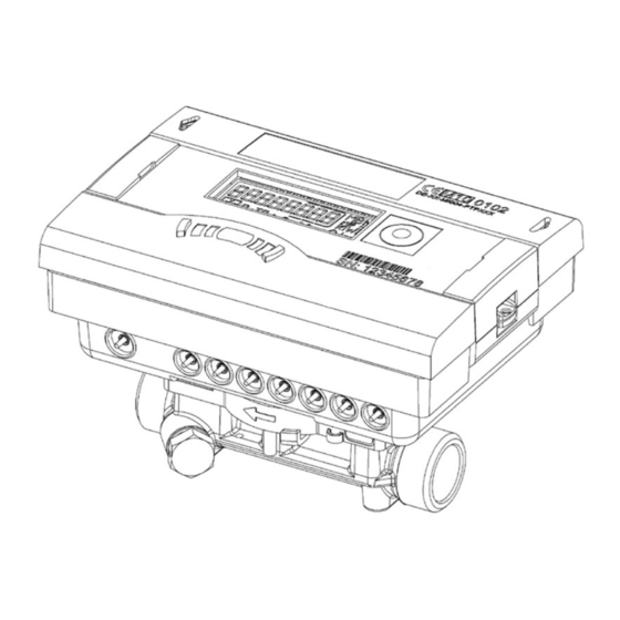
SONOMETER™ 1100
Ultrasonic compact energy meter
1.0
Table of contents
1.0
Table of contents .........................................................................................................................................................................................................................................................................1
2.0
Safety notes and product information ........................................................................................................................................................................................................................1
3.0
Installation of energy meter ................................................................................................................................................................................................................................................2
4.0
Installation of temperature sensors ...............................................................................................................................................................................................................................3
5.0
Power supply ..................................................................................................................................................................................................................................................................................4
6.0
Start-up operation ......................................................................................................................................................................................................................................................................5
7.0
Expansion modules ...................................................................................................................................................................................................................................................................5
8.0
Communication ...........................................................................................................................................................................................................................................................................6
9.0
Display .................................................................................................................................................................................................................................................................................................8
10.0 Simple operation .........................................................................................................................................................................................................................................................................9
11.0 Error codes .......................................................................................................................................................................................................................................................................................9
2.0 Safety notes and product information
Following instructions refer to the ultrasonic energy meter.
The regulations on the use of energy meters must be observed! The
meter installation is only to be performed by an installation and/
or electrical contractor using personnel trained in the installation
and use of electrical equipment and familiar with the Low Voltage
Directive.
- Medium: water, as per AGFW Instruction Sheet FW510.If water
additives are used (e.g. corrosion protection), the user must
make sure that the corrosion resistance is adequate.
- The speci ed medium temperature
is 5 ... 90°C/105°C/130°C(150°C)
- The temperature range depends on variant and nominal size
- The exact temperature range is shown on the type plate
- The encapsulated variant is to be used if condensation is
expected
- The speci ed operating/ambient conditions are:
5...55 °C; max. 93% rel. humidity
- Protection class: calculator IP54; ow sensor
IP54 (heating)/IP65 (cooling, heat/cooling)
- Ambient temperatures below 35 °C ensures typical battery
lifetime
Danfoss District Energy
This installation guide is intended for trained personnel and
does not contain any basic working steps.
If the ow sensor is insulated with the pipeline,
the calculator must be accessible.
Safety Note
The seal on the energy meter must not be damaged!
A damaged seal will result in immediate invalidation of the
factory warranty and veri cation. The cables supplied with the
meter must not be shortened, extended or changed in any
other way.
VI.SH.K1.02
1
DEN-SMT/PL
Advertisement
Table of Contents

Related Manuals for Danfoss SONOMETER 1100


Summary of Contents for Danfoss SONOMETER 1100
-
Page 1: Table Of Contents
5…55 °C; max. 93% rel. humidity meter must not be shortened, extended or changed in any - Protection class: calculator IP54; ow sensor other way. IP54 (heating)/IP65 (cooling, heat/cooling) - Ambient temperatures below 35 °C ensures typical battery lifetime Danfoss District Energy VI.SH.K1.02 DEN-SMT/PL... -
Page 2: Installation Of Energy Meter
A wall holder (supplied with meter) or a space holder (optional) is available for this purpose. T: 5 ... 90°C > T T: 5 ... 130 / 150°C water ambient < T water ambient wall mounting space holder DEN-SMT/PL VI.SH.K1.02 Danfoss District Enrgy... -
Page 3: Installation Of Temperature Sensors
Inlet Heat meter Blue (7, 8) Outlet Cold (5, 6) Inlet Heat meter with cooling tari Blue (7, 8) Outlet Cold (5, 6) Outlet Cooling meter Blue (7, 8) Inlet Cold Terminals for temperature sensors: Danfoss District Energy VI.SH.K1.02 DEN-SMT/PL... -
Page 4: Power Supply
M-Bus, RS485 and RS232 modules or the optical interface, but reduces the life of the backup battery. The radio function is switched o in the event of power supply failure. DEN-SMT/PL VI.SH.K1.02 Danfoss District Enrgy... -
Page 5: Start-Up Operation
3. Close the lid and check the meter for correct operation by pressing the push button (loop 3). Renew the seal of the housing lid if the meter functions correctly. 1 Slot 1 2 Slot 2 3 Fixing clips Danfoss District Energy VI.SH.K1.02 DEN-SMT/PL... -
Page 6: Communication
PC; 2400 bauds only. The used communication protocol is M-Bus. The module contains a 4-pole terminal strip with terminals marked D+, D-, +12 V and GND. The module needs an external power supply of 12 VDC ±5 V. DEN-SMT/PL VI.SH.K1.02 Danfoss District Enrgy... - Page 7 Ensure that the temperature sensors (measurement resistances) 2. Energy testing pulse remain in contact without interruption during energy veri cation. Please refer to the inspection and testing manual for further speci cations (pulse rate, pulse duration/pause, pulse frequency). Danfoss District Energy VI.SH.K1.02 DEN-SMT/PL...
-
Page 8: Display
1 energy volume max. flow rate max. power “6” Monthly value ,LOG’ date month 2 energy volume max. flow rate max. power loop 6.24 ,LOG’ date month 23 energy volume max. flow rate max. power DEN-SMT/PL VI.SH.K1.02 Danfoss District Enrgy... -
Page 9: Simple Operation
Battery nearly discharged, end of lifetime reached E A* Leak: Pipe break detection E b* Leak: Energy meter leak detection E C* Leak: Leak pulse input 1 E d* Leak: Leak pulse input 2 * optional ** application dependent Danfoss District Energy VI.SH.K1.02 DEN-SMT/PL... - Page 10 Instruction SONOMETER™ 1100 VI.SH.K1.02 Produced by Danfoss A/S © 12/2014...
Need help?
Do you have a question about the SONOMETER 1100 and is the answer not in the manual?
Questions and answers