
Related Manuals for Danfoss MAGFLO MAG 1100


Summary of Contents for Danfoss MAGFLO MAG 1100
- Page 1 Handbook â MAGFLO Electromagnetic flowmeters Sensor types MAG 1100, MAG 3100, MAG 5100 W Signal converter types MAG 5000, MAG 6000 521H0879 SAP No. DKFD.PS.027.W3.22 IVISION IMPLY ETTER...
- Page 2 ® MAGFLO Danfoss range of electro- MAG 1100 MAG 1100 MAG 3100 MAG 3100 W MAG 5100 W magnetic flowmeters FOOD Size [inch] " - 4" " - 4" " - 78" 1" - 48" 1" - 48" Connection Flangeless...
-
Page 3: Table Of Contents
2.8.2 Minimum accept data for cable ............................16 â HART communication add-on module ..........................16 2.10 Cable specifications (Supplied by Danfoss) ........................16 3. Product selection guidelines Sizing table ( " to 78") ..............................17 3.2.1 Minimum conductivity ................................. 18 3.2.2... -
Page 4: Product Introduction
Þ Simple to commission Þ Simple to operate Þ Simple to maintain â MAGFLO electromagnetic flowmeters are manufactured by Danfoss A/S, Flow Division - one of the worlds leading makers of flowmeters. â ® All MAGFLO electromagnetic flowmeters feature a unique SENSORPROM memory unit which stores sensor calibration data and signal converter settings for the lifetime of the product. -
Page 5: Mode Of Operation
â 1. Product introduction MAGFLO The flow measuring principle is based on Faraday’s law of electromagnetic induction. The flowmeter Mode of operation consists of a sensor type MAG 1100, 3100 or 5100 W and a signal converter type MAG 5000 or 6000. = When an electrical conductor of length L is moved at velocity v, perpendicular to the lines of flux through a magnetic field of strength B, the voltage U is induced at the ends of the conductor... -
Page 6: Specifications
® 2. Specifications MAG 1100 and MAG 1100 Ex MAGFLO Specifications 2.1 Sensor MAG 1100 and MAG 1100 Ex MAG 1100 Ex MAG 1100 Ceramic MAG 1100 PFA Type Flangeless sensor (Wafer) ", ", 1", 1 ", 2", 3", 4" Nominal size ", ",... -
Page 7: Sensor Mag 1100 Food
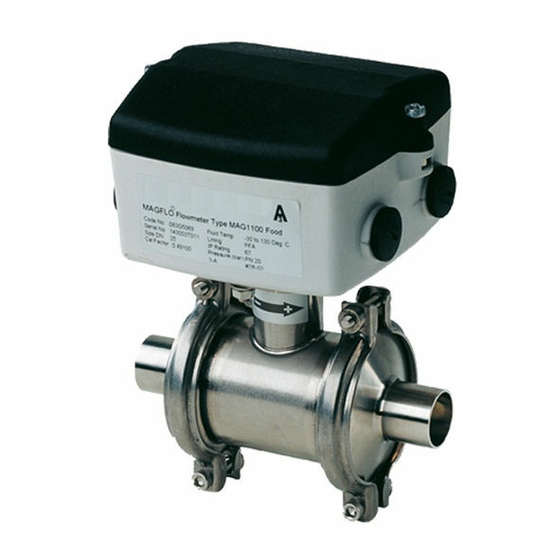
® 2. Specifications MAG 1100 FOOD MAGFLO 2.2 Sensor MAG 1100 FOOD MAG 1100 FOOD MAG 1100 FOOD PFA Type Hygienic sensor Nominal size ", ", 1", 1 ", 2", 3", 4" Process connection Hygienic adapters available for: ♦ Direct welding in ♦ Clamp fitting ♦ Threaded fitting Operating pressure "-2 ": 600 psi, 3": 560 psi, 4": 450 psi... -
Page 8: Sensor Mag 3100, Mag 3100 Ex And Mag 3100 W
â MAGFLO 2. Specifications MAG 3100, MAG 3100 Ex and MAG 3100 W 2.3 Sensor MAG 3100, MAG 3100 Ex and MAG 3100 W MAG 3100 MAG 3100 Ex MAG 3100 W Type Sensor with flanges Sensor with flanges Sensor with flanges Nominal size "... - Page 9 â MAGFLO 2. Specifications MAG 3100, MAG 3100 Ex and MAG 3100 W 2.3 Sensor MAG 3100, MAG 3100 Ex and MAG 3100 W (continued) MAG 3100 MAG 3100 Ex MAG 3100 W Flanges Standard DN 15-50: 600 psi DN 25-50: 600 psi EN 1092-1:2001 DN 65-150:...
-
Page 10: Sensor Mag 5100 W
â MAGFLO 2. Specifications MAG 5000 and MAG 5000 CT 2.4 Sensor MAG 5100 W Type Sensor with flanges Design Straight Coned down 1 pipe size Straight Nominal size inch 1" - 1½" 2" - 12" 14" - 48" Liner Hard elastomer Composite elastomer Hard elastomer... -
Page 11: Signal Converter Mag 5000 ( / " To 48")
â MAGFLO 2. Specifications MAG 5000 and MAG 5000 CT 2.5.1 Signal converter MAG 5000 ( " to 48") Accuracy 0.5% Current output Active current 0-20 mA, 4-20 mA or 4-20 mA + alarm (Power supplied from flowmeter) Load < 800 ohm Time constant 0.1-30 sec. -
Page 12: Signal Converter Mag 6000 ( / " To 78")
â MAGFLO 2. Specifications MAG 6000 and MAG 6000 CT 2.5.2 Signal converter MAG 6000 ( " to 78") Accuracy 0.25% (0.5% for MAG 3100 W sensor) Current output Active current 0-20 mA, 4-20 mA or 4-20 mA + alarm (Power supplied from flowmeter) Load <... -
Page 13: Safety Barrier (Ia/Ib) For Sizes Up To 12
â 2. Specifications Safety barrier & cleaning unit MAGFLO 2.5.3 Application As combined unit with MAG 6000 only and MAG 1100 Ex/3100 Ex in the size Safety barrier (ia/ib) range " - 12" for sizes up to 12'’ Ex approval [EEx ia/ib] IIB Cable parameter Group... -
Page 14: Meter Uncertainty
â 2. Specifications MAGFLO MAG 5000 or MAG 6000 used with MAG 3100 W or MAG 1100 PFA Meter uncertainty V: Actual flow velocity [ft./s] E: Meter uncertainty as a percentage of actual flow MAG 6000 used with MAG 3100, MAG 1100 Ceramic or MAG 5100 W V: Actual flow velocity [ft./s] E: Meter uncertainty as a percentage of actual flow Reference conditions (ISO 9104 and DIN/EN 29104) -
Page 15: Output Characteristics Mag 5000 And Mag 6000
â MAGFLO 2. Specifications Output characteristics Bidirectional mode Unidirectional mode Output characteristics 0-20 mA MAG 5000 and MAG 6000 4-20 mA Frequency Pulse output Relay Power down Active Error relay No error Error Limit switch or 1 set point 2 set points direction switch Low flow Intermediate flow... -
Page 16: Sensor Cables And Conductivity Of Medium
Twisted pair â HART is a registered trademark of the HART Communication Foundation. Standard cable Special cable Cable specification (electrode/coil) (electrode) (Supplied by Danfoss) Basic data No. of conductors Sqr. area 1.5 mm /18 gage 0.25 mm /22 gage Shield... -
Page 17: Sizing Table ( 1 / 4 " To 78")
â 3. Product selection guidelines MAGFLO Product selection guidelines 3.1 Sizing table ( " to 78") The table shows the relationship between flow velocity V, flow quantity Q and sensor dimension size. Guidelines for selection of sensor Min. measuring range: 0-0.8 ft./sec. Max. measuring range: 0-33 ft./sec. Normally the sensor is selected so that the nominal flow velocity is within the measuring range 1-15 ft./sec. -
Page 18: Minimum Conductivity
â 3. Product selection guidelines MAGFLO 3.2.1 Applications Min. conductivity Minimum conductivity Integral mounted 5 mS/cm Remote mounted 5 mS/cm (Please see 2.7.1 for further details) 20 mS/cm (Please see 2.7.1 for further details) With empty pipe detection Ex-installations (Remote mounted only) 30 mS/cm (Please see 2.7.1 for further details) District heating systems (Without DC cleaning unit) -
Page 19: Installation Conditions
â 3. Product selection guidelines MAGFLO To ensure optimum flow measurement, atten- Installation conditions tion should be paid to the following: (continued) The sensor must always be completely full with liquid. Avoid: · Installation at the highest point in the pipe system ·... - Page 20 â 3. Product selection guidelines MAGFLO Potential equalization The electrical potential of the liquid must al- (Grounding) ways be equal to the electrical potential of the sensor. This can be achieved in different ways depending on the application: A. Built-in grounding electrodes. (MAG 3100 and MAG 3100 W).
- Page 21 â 3. Product selection guidelines MAGFLO Integral mount/remote The sensor and signal converter can be in- installation stalled either integral mount or remote. With integral mount installation the tempera- ture of medium must be according to the graph. With remote installation, the cable length and type described under "Specifications", section 2 must be used.
-
Page 22: Cleaning Unit
â 3. Product selection guidelines MAGFLO The Danfoss cleaning unit can be used with MAG 5000 or 6000 in rack mount versions. The cleaning unit can be used in applications where the liner material and subsequently the Cleaning unit electrodes may be coated with deposits. If the coating is electrically insulating, the electrode signal will be reduced. -
Page 23: Custody Transfer Approval
â 3. Product selection guidelines MAGFLO A signal converter can be supplied in a version Custody transfer tested and approved for custody transfer (CT). approval The internal counter can accordingly be used for billing. This requires verification, sealing and setting of the signal converter together with the sensor for a specific flow range. -
Page 24: Ex Installations
â 3. Product selection guidelines MAGFLO MAG 6000 rack mount with integral safety barrier (ia/ib) for remote mounting in safe area Approval [EEx ia/ib] llB. The safety barrier is to be used with sensors MAG 1100 Ex and MAG 3100 Ex installations "... -
Page 25: Dimensions And Weight
â MAGFLO 4. Dimensions and weight 4. Dimensions and weight MAG 1100, integral/remote mount/separate Sensor MAG 1100 Signal converter removal clearance Size Weight (PFA) [inch] [inch] [inch] [inch] [inch] [inch] [inch] [inch] [inch] [lbs] " 6.14 7.13 12.16 13.15 1.90 0.24 0.68 1.34... -
Page 26: Sensor Mag 1100 Food
â MAGFLO 4. Dimensions and weight MAG 1100 FOOD, integral or remote mount and separate Sensor MAG 1100 FOOD Signal converter removal clearance Size Weight (PFA) [inch] [inch] [inch] [inch] [inch] [inch] [inch] [inch] [lbs] " 2.52 6.14 12.16 7.40 13.43 2.52 0.39... - Page 27 â MAGFLO 4. Dimensions and weight Accessories Weld-in type Adapter Sensor MAG 1100 FOOD ® Tri-Clover size size [inch] [inch] [inch] [inch] [inch] 0.37 0.62 0.87 1.37 1.87 2.37 2.87 3.83 Clamp type Adapter Sensor ® Tri-Clamp size size [inch] [inch] [inch] [inch] [inch] 0.37...
-
Page 28: Sensor Mag 5100 W
â 4. Dimensions and weight MAGFLO Sensor MAG 5100 W Dimensions Nominal PN 10 PN 16 PN 40 Class 150 AWWA size inch inch inch inch inch inch inch 1" 1½” 2" 2½” 3" 4" 5" 6" 11.8 11.8 8" 10.1 13.8 13.8... - Page 29 â MAGFLO 4. Dimensions and weight MAG 5100 W weight Nominal size PN 10 PN 16 PN 40 Class 150 AWWA inch 1" 1½” 2" 2½” 10.7 3" 11.6 4" 15.2 5" 20.4 6" 8" 10" 12" 14" 16" 18" 20"...
-
Page 30: Sensor Mag 3100 And Mag 3100 W
â 4. Dimensions and weight MAGFLO MAG 3100 & MAG 3100 W, integral or remote mount and separate Sensor MAG 3100 and MAG 3100 W Size Weight EN 1092-1-2001 ANSI 16.5 AWWA C-207 Class Class Class 2.52 [inch] [inch] [inch] [inch] [inch] [inch] [inch] [inch] [inch] [inch] [inch] [inch] [inch]... -
Page 31: Signal Converter
â 4. Dimensions and weight MAGFLO Grounding/protection ring Weight Weight Size Size [inch] [lbs] [inch] [inch] [lbs] " 0.15 1" to 10" 0.05 <1 1" to 6" 12" to 24" 0.06 8" to 14" 28" to 48" 0.08 6-11 16 to 24" 14-28 54"... - Page 32 â 4. Dimensions and weight MAGFLO Wall mounting converter Weight excl. signal converter: 8.0 lbs Wall mounting converter with cleaning unit or intrincically safe barrier Weight excl. signal converter: 7.0 lbs Front panel mounting kit Weight excl. signal converter: 3.0 lbs...
- Page 33 â 4. Dimensions and weight MAGFLO Front panel mounting kit for converter with intrinsi- cally safe barrier or cleaning unit Weight excl. signal converter: 3.5 lbs Back of panel mounting kit Weight: 2.0 lbs Back of panel mounting kit for converter with intrinsi- cally safe barrier or cleaning unit Weight: 2.0 lbs...
-
Page 34: Installation Of Sensor
â MAGFLO 5. Installation of sensor 5. Installation of sensor To obtain optimum results from the measuring system, the chassis body of the sensor must have the same electrical potential as the liquid being measured. Potential equalization Graphite gaskets EPDM or PTFE gaskets (Grounding) MAG 1100 Electrically... -
Page 35: Inlet Protection Mag 3100
â 5. Installation of sensor MAGFLO MAG 3100 Electrically conductive piping PTFE liner Use a grounding straps on one side. Potential equalization, electrically conductive pipe Non-conductive piping Use an grounding ringe. Place the ring between flowmeter and the adjacent pipe flange. Selection of grounding ring depends on me- dium, liner material and application. -
Page 36: Installation Of Signal
â MAGFLO 6. Installation of signal converter 6. Installation of signal Step 1 converter Remove and discard the terminal box lid of the sensor. Integral installation Fit the PG 13.5 cable glands for the supply and MAG 5000 and MAG 6000 output cables. - Page 37 â MAGFLO 6. Installation of signal converter Step 1 Turning the control pad Use a screw driver to remove the outer frame. Step 2 Loosen the 4 screws retaining the control pad. Step 3 Withdraw the control pad and turn it to the required orientation.
-
Page 38: Add-On Modules (Mag 6000 Only)
â 6. Installation of signal converter MAGFLO 6.2.1 Locate the add-on module in the bottom of the Add-on modules MAG 6000 signal converter. (MAG 6000 only) Press the add-on module forwards as far as possible. The add-on module has now been installed and the signal converter is ready to be installed on the terminal box. -
Page 39: Remote Installation Wall Mount
â MAGFLO 6. Installation of signal converter 6.2.3 Step 3 (Wall mounting) Remote installation Mount wall bracket on a wall or in the back of a panel. Wall mount MAG 6000 & MAG 5000 Vertical pipe mounting Mount the wall mounting on a vertical or hori- zontal pipe using an ordinary hose clamp or a duct strap. - Page 40 â MAGFLO 6. Installation of signal converter 6.2.3 Step 4 (wall mounting) Remote installation Remove the SENSORPROM ® unit from the sensor terminal ® Remove the SENSORPROM unit Wall mount box. Mount the SENSOR- (continued) PROM ® unit in the wall mount- ing terminal box as shown.
-
Page 41: Remote Installation Rack Mount
â MAGFLO 6. Installation of signal converter 6.2.4 Remote installation Rack mount (continued from page 38) (From sensor terminal box) Step 1 + 2 Please refer to page 38. Step 3 (Rack mount units) Mount the SENSORPROM ® memory unit on the connection board supplied with the signal ®... -
Page 42: Add-On Modules (Mag 6000 Only)
â MAGFLO 6. Installation of signal converter 6.2.5 Locate the add-on module in the bottom of the Add-on modules MAG 6000 signal converter. (MAG 6000 only) Press the add-on module forwards as far as possible. The add-on module has now been installed and the signal converter is ready to be installed terminal box. -
Page 43: Installation Using Wall Mounting Kit
â MAGFLO 6. Installation of signal converter 6.2.6 Installation using wall mounting kit (continued from page 38) (From sensor terminal box) Step 1 + 2 Please refer to page 38. Step 3 (Rack mount units) Mount the NEMA 4X enclosure on the wall with four screws. Step 4 (Rack mount units) Mount the SENSORPROM ®... -
Page 44: Installation Using Front Of Panel Mounting Kit
â 6. Installation of signal converter MAGFLO 6.2.7 Installation using front of panel mounting kit (continued from page 38) (From sensor terminal box) Step 1 + 2 Please refer to page 38. Step 3 (Rack mount units) Mount the SENSORPROM ®... -
Page 45: Installation Using Back Of Panel Mounting Kit
â MAGFLO 6. Installation of signal converter 6.2.8 Installation using back of panel mounting kit (continued from page 38) (From sensor terminal box) Step 1 + 2 Please refer to page 38. Step 3 (Rack mount units) Mount the SENSORPROM ®... -
Page 46: Signal Converter With Safety Barrier
â MAGFLO 6. Installation of signal converter Signal converter with safety barrier (continued from page 38) (From sensor terminal box) Step 1 + 2 Please refer to page 38. Step 3 (Rack mount units) Fit the SENSORPROM ® memory unit on the connection board supplied with the safety barrier. The SENSORPROM ®... -
Page 47: Signal Converter With Cleaning Unit
â 6. Installation of signal converter MAGFLO Signal converter with cleaning unit (continued from page 38) (From sensor terminal box) Step 1 + 2 Please refer to page 38. Step 3 (Rack mount units) Fit the SENSORPROM ® memory unit on the connection board supplied with the cleaning unit. The SENSORPROM ®... -
Page 48: Electrical Connection
â MAGFLO 7. Electrical connection 7. Electrical connection Signal converter MAG 5000 and MAG 6000 connection diagram Safety Note Only qualified personnel should perform wiring or repairs, and only when the signal converter is not powered. Install signal converter in accordance with all relevant NEC and local codes. -
Page 49: Wiring Diagram For Signal Converter And Sensor
â 7. Electrical connection MAGFLO Integral mount Wiring diagram for signal converter and sensor 7.2.1 Integral installation Note Mount a grounding wire to the PE on the connnection board to ensure sufficient grounding. Cathodic protected piping Integral mount installation: The signal converter must be supplied through an isolation transformer. The terminal "PE" must not be connected. -
Page 50: Rack Mount Nema 2 Enclosure
â MAGFLO 7. Electrical connection 7.2.3 Rack mount NEMA 2 enclosure 7.2.4 Wall mount NEMA 4X enclosure 7.2.5 Rack mount with safety barrier NEMA 2 EEx (ia/ib) up to 12''... -
Page 51: Wall Mount With Safety Barrier Nema 6 Eex (Ia/Ib) Up To 12
â 7. Electrical connection MAGFLO 7.2.6 Wall mount with safety barrier NEMA 6 EEx (ia/ib) up to 12'' 7.2.7 Rack mount NEMA 2 with cleaning unit 7.2.8 Wall mount NEMA 6 with cleaning unit... -
Page 52: Start-Up & Programming
â MAGFLO 8. Start-up & programming 8. Commissioning Keypad and display layout Keypad The keypad is used to program the flowmeter. The function of the keys is as follows: TOP UP KEY This key (hold 2 sec.) is used to switch between operator menu and setup menu. -
Page 53: Menu Build-Up
â 8. Start-up & programming MAGFLO The menu structure of a specific signal converter type is shown in a menu overview map. Details of how a specific parameter is set is shown in a menu detail map for the specific parameter. Menu build-up A detail map is valid for each type of signal converter if not indicated otherwise. -
Page 54: Mag 5000 And Mag 6000
â MAGFLO 8. Start-up & programming Menu overview 8.3.1 MAG 5000 and MAG 6000... -
Page 55: Mag 6000 Ct
â 8. Start-up & programming MAGFLO Menu overview 8.3.2 MAG 6000 CT... -
Page 56: Basic Settings
â MAGFLO 8. Start-up & programming Menu detail 8.4.1 Main frequency Basic settings To select the main power supply frequency corresponding to the country in which the flowmeter is installed. (US = 60 Hz) Flow direction Select the correct flow direction in the pipe max. -
Page 57: Outputs
â 8. Start-up & programming MAGFLO Menu detail 8.4.2 Outputs Current output Proportional to flowrate (Terminal 31 and 32) 4 - 20 mA + alarm: Current output gives the following mA, depending on what is selected as error level in basic settings. Fatal: 1 mA, permanent: 2 mA, warning: 3 mA The current output must be turned off when not used. -
Page 58: Relay Output
â MAGFLO 8. Start-up & programming Menu detail Limit/direction Limit switches are available for both digital as well as relay output. Direction mode: 1 set point at 0% flow; hysteresis 5%. If 2 set points must activate 2 separate outputs, a single set point has to be selected individually for digital as well as relay outputs. -
Page 59: Sensor Characteristics
â 8. Start-up & programming MAGFLO Menu detail 8.4.6 Sensor characteristics If “SENSORPROM not installed” is shown, refer to section 6 (depending on type of mounting configura- tion). 8.4.7 Reset mode... -
Page 60: Service Mode
â Menu detail MAGFLO 8. Start-up & programming 8.4.8 Service mode 1) Standard 2) If digital output is set to frequency All previous settings are reinitialized when service mode is exited using the top up key The error system The error system is divided into an error pending list and a status log list. Time is displayed as days, minutes and hours since the error has occurred. -
Page 61: Operator Menu Setup
â 8. Start-up & programming MAGFLO Menu setup 8.4.9 Operator menu setup Text means that the text for the chosen measured value is shown. For example if text is chosen in line 2 and flow rate is chosen in line 3, the text “flow rate” is shown in line 2 and the measured flow rate value is show in line 3. -
Page 62: Product Identity (Read Only)
â MAGFLO 8. Start-up & programming Menu detail 8.4.10 Product identity (Read only) Software version of add-on module is only available if the add-on module has been installed. 8.4.11 If you have forgotten your password please Change password refer to 8.2.1 on how to reset your password back to factory setting, 1000. -
Page 63: Language Mode
â 8. Start-up & programming MAGFLO Menu detail 8.4.12 Language mode Used to select language. 8.4.13 â HART communication MAG 5000 HART or as add-on module... -
Page 64: Flow Rate
â MAGFLO 8. Start-up & programming Operator menu 8.5.1 Operator menu Flow rate The 1 display line is always active and shows the value enabled in the operator menu setup. · Flow rate Totalizer 1 · · Totalizer 2 The 2 and 3 display lines are individually set in the operator menu. -
Page 65: Factory Settings/Available Settings
â 8. Start-up & programming MAGFLO 8.6.1 The signal converter is delivered with factory settings ready to measure the actual flow. Factory settings/available Parameter Factory settings Available settings settings Password Default value 1000 Password 1000 1000 - 9999 Basic settings Flow direction Positive Positive, negative... -
Page 66: Dimension Dependent Factory Settings Mag 5000 And Mag 6000
â MAGFLO 8. Start-up & programming 8.6.2 max. Dimension dependent MAG 5100 W MAG 1100, factory settings 3100, 3100 W Volume/ Pulse Totalizer MAG 5000 and [inches] fac.set. min. max. min. max. unit pulse unit unit MAG 6000 0.11 US GPM US G US G MAG 1100... -
Page 67: Mag 6000 Ct Settings
â 8. Start-up & programming MAGFLO 8.6.4 Setting primary operating parameters such as Q , low flow cut-off, units, approvals, etc. is blocked max. MAG 6000 CT settings during normal operation. See menu setup. These settings are made in connection with commissioning or calibration by mounting a hardware key on solder terminals of the connection plate of the signal converter. -
Page 68: Error Handling
â MAGFLO 8. Start-up & programming 8.7.1 Error system Error handling The converter system is equipped with an error and status log system with 4 groups of information. · Information without a functional error involved · Warnings which may cause malfunction in the application. The cause of the error may disappear on its own ·... -
Page 69: List Of Error Numbers
â 8. Start-up & programming MAGFLO 8.7.2 Error Error text #Comment Outputs Input List of error numbers Remedy text status status I1 - Power on Power on has happened Active Active I2 - Add-on module Applied A new module has been applied to the system Active Active I3 - Add-on module... -
Page 70: Service
â 9. Service MAGFLO Often problems with unstable/wrong measurements occur due to insufficient/wrong grounding or 9. Service â potential equalization. Please check connection. If OK, the MAGFLO converter can be checked as described under 9.1 and sensor under 9.3. â When checking MAGFLO installations for malfunction the easiest method to check the signal Converter check list... -
Page 71: Trouble Shooting Mag 5000 And Mag 6000
â 9. Service MAGFLO Symptom Output Error Cause Remedy Trouble shooting signals code MAG 5000 and MAG 6000 Empty display Minimum 1. No power supply Power supply Check MAG 5000/6000 for bended pins on the connector 2. MAG 5000/6000 defective Replace MAG 5000/6000 No flow signal Minimum... -
Page 72: Check List Mag Sensor
Check coil insulation with a megger (500 V) Sensor may be defective. R 85 - Gnd Nominal value: Infinite resistance Contact Danfoss > 500 kohm Check electrode circuit with a moving-coil instru- ment without amplifier (measurement unstable) R 82 - Gnd... -
Page 73: Coil Resistance Table
â 9. Service MAGFLO Coil resistance for MAG 1100, MAG 1100 PFA = 98 ohms +/- 4 ohm Coil resistance table Note On MAG 1100 ½” produced as from May 1999 the coil resistance must be 86 ohm, +8/-4 ohm. Coil resistance MAG 3100 MAG 3100 W... -
Page 74: Ordering
â MAGFLO 10. Ordering 10. Ordering Description Size Code No. Symbol MAG 1100 " 083G4044 10.1 Ceramic Al " 083G4046 Sensor MAG 1100 Temperature of medium max. 300°F " 083G4047 Included: 1" 083G4049 2 EPDM gaskets, studs and nuts " 083G4051 2"... -
Page 75: Adapter, Mag 1100 Food (Contains 2 Adapters, 2 Clamp Rings And 2 Gaskets)
â 10. Ordering MAGFLO Gaskets for Description Material Size Code No. Symbol MAG 1100 EPDM gaskets EPDM ", " 083G3116 2 gaskets " 083G3117 2 earth straps 1" 083G3119 3 M6 screws " 083G3121 2" 083G3122 " 083G3123 3" 083G3124 4"... -
Page 76: Sensor Mag 3100 And Mag 3100 Ex
â 10. Ordering MAGFLO 10.3 Type No.: MAG 3100 - Sensor MAG 3100 and MAG 3100 Ex 1. Nominal size (inch) ½" ................1" ................1½" ................2" ................2½" ................3" ................4" ................5" ................6" ................8" ................10"... - Page 77 â MAGFLO 10. Ordering Grounding/protection Flange EN 1092-1 ANSI B 16.5 AWWA C207 flange type C (AISI 304) for Pressure PN 6 PN 10 PN 16 PN 25 PN 40 150 lb 300 lb Class D all liners except PTFE stage for MAG 3100 and 3100 W Size...
-
Page 78: Sensor Mag 3100 W
â MAGFLO 10. Ordering 10.4 Nominal Flange type Code No. Sensor MAG 3100 W ANSI/AWWA flanges size Neoprene EDPM inch liner liner 1" ANSI 150 083Z8600 083Z8650 Liner: Neoprene or EPDM 1½" ANSI 150 083Z8601 083Z8651 Flange: Carbon steel (A 105/St. 37.2), 2"... -
Page 79: Sensor Mag 5100 W
â 10. Ordering MAGFLO 10.5 Size Factory Flange max. Sensor MAG 5100 W inches set GPM Min. Max. type Code No. 77.8 ANSI 150 082Z8501 1½ 198.1 ANSI 150 082Z8503 277.4 ANSI 150 082Z8505 2½ 11.0 440.3 ANSI 150 082Z8507 17.6 704.5 ANSI 150... -
Page 80: Signal Converter
â MAGFLO 10. Ordering 10.6 Description Version Enclosure Code No. Symbol Signal converter Signal converter MAG 5000 Blind for 11-30 V d.c./ NEMA 4X, fibre- integral mount and wall mounting 11-24 V a.c. glass reinforced 083F5006 Integral mount polyamide polyamide 115/230 V a.c. -
Page 81: Signal Converter Rack Mount
â MAGFLO 10. Ordering 10.7 Description Version Code No. Symbol Signal converter rack Signal converter MAG 5000 for rack 11-30 V d.c./ 083F5021 mount and panel mounting 11-24 V a.c. 115-230 V a.c. 083F5020 50/60 Hz Signal converter MAG 6000 for rack 11-30 V d.c./ 083F5023 and panel mounting... -
Page 82: Accessories
â MAGFLO 10. Ordering Back plates Description Enclosure Version Code No. Symbol Signal converter rack mount 12-24 V 083F4117 115-230 V Signal converter & ia, safety barrier rack mount 12-24 V 083F4118 115-230 V Signal converter & ia/ib, safety barrier rack mount 12-24 V 083F4119... -
Page 83: Calibration
Customer specified matched pair Sensor with signal converter calibrated in max. 10 customer specified points Code No.: On application form to be filled Accredited Danfoss matched pairs in and sent to FD-GB Calibrations acc. to EN 45001 Sealing and labeling instruction must follow... - Page 84 The Danfoss A/S, Flow Division range contains: â â MAGFLO electromagnetic flowmeters SONOFLO ultrasonic flowmeters â â MAGFLO flowmeters are used for all electrically conductive SONOFLO flowmeters measure flow in full pipes. â liquids. SONOFLO flowmeters measure media in liquid form, irrespec- A wide range is offered for: tive of electrical conductivity.
Need help?
Do you have a question about the MAGFLO MAG 1100 and is the answer not in the manual?
Questions and answers
GSD file for Danfoss MAG 6000 and MAG 1100 flowmeter