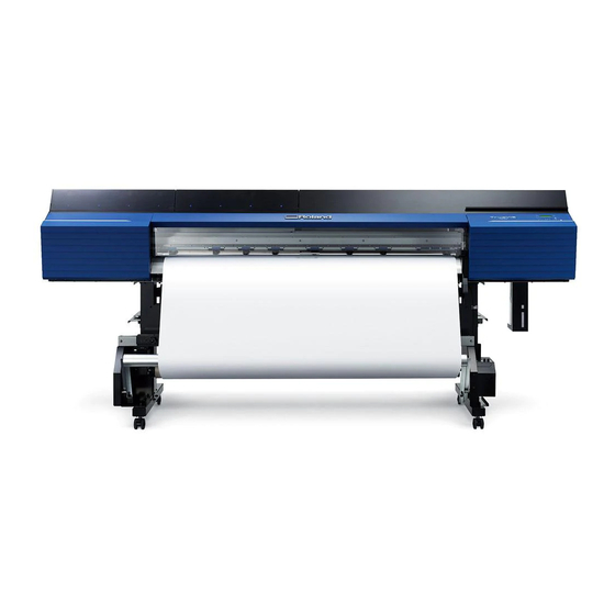
Roland TrueVIS VG2-640 Setup Manual
Hide thumbs
Also See for TrueVIS VG2-640:
- User manual (319 pages) ,
- Regular maintenance manual (34 pages)
Table of Contents
Advertisement
Quick Links
This machine has a built-in inductive reading/writing communication device that uses radio waves (an RFID device).
• RFID is used to read the information inscribed on the ink pouches (or cartridges).
• If you use a pacemaker or other implanted medical equipment, do not approach this machine.
• Do not use this machine within hospitals.
• Thank you very much for purchasing this product.
• To ensure correct and safe usage with a full understanding of this product's performance, please be sure to read
through this manual completely and store it in a safe location.
• Unauthorized copying or transferal, in whole or in part, of this manual is prohibited.
• The specifications of this product and the contents of this operation manual are subject to change without no-
tice.
• This manual and the product have been prepared and tested as much as possible. If you find any misprints or
errors, please inform Roland DG Corporation.
• Roland DG Corporation assumes no responsibility for any direct or indirect loss or damage that may occur
through use of this product, regardless of any failure to perform on the part of this product.
• Roland DG Corporation assumes no responsibility for any direct or indirect loss or damage that may occur with
respect to any article made using this product.
R1-190208
Setup Guide
Advertisement
Chapters
Table of Contents

Related Manuals for Roland TrueVIS VG2-640


Summary of Contents for Roland TrueVIS VG2-640
- Page 1 • Roland DG Corporation assumes no responsibility for any direct or indirect loss or damage that may occur with respect to any article made using this product.
- Page 2 • Using Bluetooth communication in the vicinity of TVs or radios may lead to noise in the image or au- dio. • Roland DG Corporation accepts no responsibility for the leakage of information during a connection using Bluetooth technology. • The mobile terminal that you are using to connect to the printer must comply with Bluetooth stan- dards determined by the Bluetooth SIG and must be a certified device.
-
Page 3: Table Of Contents
VG2-640 — 64-inch model VG2-540 — 54-inch model Most of the figures in this document depict the VG2-640. Company names and product names are trademarks or registered trademarks of their respective holders. Copyright © 2019 Roland DG Corporation http://www.rolanddg.com/... - Page 4 For the USA and Canada FCC CAUTION Changes or modifications not expressly approved by the party responsible for compliance could void the user’s authority to operate the equipment. This transmitter must not be co-located or operated in conjunction with any other antenna or transmitter. This device complies with Part 15 of FCC Rules and Industry Canada’s licence-exempt RSSs.
- Page 5 COMMISSION RADIO FREQUENCY INTERFERENCE STATEMENT Manufacturer: ROLAND DG CORPORATION 1-6-4 Shinmiyakoda, Kita-ku, Hamamatsu-shi, Shizuoka-ken, Responsible Party : Roland DGA Corporation 431-2103 JAPAN Address : 15363 Barranca Parkway Irvine, CA 92618 U.S.A. Telephone : 949-727-2100 The importer in the EU: Type of Equipment :Printer Roland DG Europe Holdings B.V.
- Page 6 For China 产品中有毒有害物质或元素的名称及含量 有毒有害物质或元素 部件名称 六价铬 多溴联苯 多溴二苯醚 铅(Pb) 汞(Hg) 镉(Cd) (Cr(Ⅵ)) (PBB) (PBDE) 印刷电路板 × ○ × ○ ○ ○ 头部 × ○ ○ ○ ○ ○ 壳体、底架 × ○ ○ ○ ○ ○ 电源 × ○ × ○ ○...
-
Page 7: To.ensure.safe.use
To Ensure Safe Use Improper.handling.or.operation.of.this.machine.may.result.in.injury.or.damage.to.property..Points. which.must.be.observed.to.prevent.such.injury.or.damage.are.described.as.follows.. About WARNING and CAUTION Notices Used.for.instructions.intended.to.alert.the.user.to.the.risk.of.death.or.severe.injury. should.the.unit.be.used.improperly. WARNING Used.for.instructions.intended.to.alert.the.user.to.the.risk.of.injury.or.material.damage. should.the.unit.be.used.improperly. CAUTION *Material.damage.refers.to.damage.or.other.adverse.effects.caused.with.respect.to.the. home.and.all.its.furnishings.as.well.as.to.domestic.animals.or.pets. About the Symbols The. .symbol.alerts.the.user.to.important.instructions.or.warnings. The.specific.meaning.of.the.symbol.is.determined.by.the.design.contained.within.the. symbol. The.symbol.at.left.means."danger.of.electrical.shock." The. .symbol.alerts.the.user.to.items.that.must.never.be.carried.out.(are.forbidden). The.specific.meaning.of.the.symbol.is.determined.by.the.design.contained.within.the. symbol. The.symbol.at.left.means.the.unit.must.never.be.disassembled. The. .symbol.alerts.the.user.to.things.that.must.be.carried.out. The.specific.meaning.of.the.symbol.is.determined.by.the.design.contained.within.the. symbol. The.symbol.at.left.means.the.power-cord.plug.must.be.unplugged.from.the.outlet. - Page 8 To Ensure Safe Use This is a heavy machine. WARNING WARNING Install the machine in a location that Handling roll media is an operation that is level, stable, and able to bear the must be performed by two persons or weight of the machine after checking more, and care must be taken to pre- the weight of the machine in the oper-...
- Page 9 To Ensure Safe Use Incorrect operation may cause injury WARNING CAUTION Be sure to follow the operation proce- Exercise caution to avoid being pinched dures described in the user’s manual. or becoming caught. Never allow anyone unfamiliar with the Inadvertent.contact.with.certain.areas.may. usage or handling of the machine to cause.the.hand.or.fingers.to.be.pinched.or.
- Page 10 Never use if any component is damaged. Continuing.to.use.the.machine.may.result. in.fire,.electrical.shock,.or.injury..Contact. Never allow any foreign object to get in- your.authorized.Roland.DG.Corp..dealer. side. Never expose the machine to liquid spills. Inserting.objects.such.as.coins.or.matches. Do not use the supplied power cord for or.allowing.beverages.to.be.spilled.into.
- Page 11 To Ensure Safe Use Important notes about the power cord, plug, and electrical outlet Never place any object on top or Never allow to get wet. Never bend or twist with undue subject to damage. force. Never make hot. Never pull with undue force. Dust may cause fire.
- Page 12 To Ensure Safe Use Ink, cleaning liquid, and discharged fluid are flammable and toxic CAUTION WARNING Ensure adequate ventilation for the work Keep open flame away from the work area. area. Failing.to.perform.ventilation.may.result.in. Ink.and.discharged.fluid.are.flammable. a.health.hazard.or.danger.of.combustion. due.to.ink.fumes. Never store ink, cleaning liquid, or discharged fluid in any of the following Never allow an ink container (such as a locations.
- Page 13 To Ensure Safe Use Warning Labels A.warning.label.is.affixed.to.the.machine.to.make.areas.of.danger.immediately.clear..The.meaning.of. this.label.is.indicated.below..Be.sure.to.heed.this.warning..Also,.never.remove.the.label.or.allow.it.to. become.dirty. Caution: High Temperature The.platen.and.dryer.become.hot..Exercise.caution.to.avoid.fire.or.burns. Caution: Pinching Hazard Be.careful.not.to.allow.the.fingers.to.become.pinched.when.closing.covers. Caution: Moving Print Heads The.print.heads.inside.the.cover.move.at.high.speed.and.pose.a.hazard.. Never.insert.the.hand.or.fingers.into.the.gap. Ink, cleaning fluid, and discharged fluid are flammable and toxic. If.these.fluids.come.into.contact.with.the.eyes.or.skin,.it.may.be.hazardous. to.the.health..When.performing.maintenance.work,.for.example.when.dis- posing.of.discharged.fluid,.wear.protective.eyewear.and.protective.gloves. (refer.to.the.safety.data.sheet.[SDS]). Caution: High Voltage Removing.the.cover.may.result.in.high-voltage.electric.shock.
-
Page 14: Pour.utiliser.en.toute.sécurité
Pour utiliser en toute sécurité La.manipulation.ou.l’utilisation.inadéquates.de.cet.appareil.peuvent.causer.des.blessures.ou.des. dommages.matériels..Les.précautions.à.prendre.pour.prévenir.les.blessures.ou.les.dommages.sont. décrites.ci-dessous. À propos des avis ATTENTION et PRUDENCE Utilisé.pour.avertir.l’utilisateur.d’un.risque.de.décès.ou.de.blessure.grave.en.cas.de.mau- vaise.utilisation.de.l’appareil. ATTENTION Utilisé.pour.avertir.l’utilisateur.d’un.risque.de.blessure.ou.de.dommage.matériel.en.cas. de.mauvaise.utilisation.de.l’appareil. PRUDENCE *.Par.dommage.matériel,.il.est.entendu.dommage.ou.tout.autre.effet.indésirable.sur.la. maison,.tous.les.meubles.et.même.les.animaux.domestiques. À propos des symboles Le.symbole. .attire.l’attention.de.l’utilisateur.sur.les.instructions.importantes.ou.les. avertissements. Le.sens.précis.du.symbole.est.déterminé.par.le.dessin.à.l’intérieur.du.symbole. Le.symbole.à.gauche.signifie.«.danger.d’électrocution.». Le.symbole. .avertit.l’utilisateur.de.ce.qu’il.ne.doit.pas.faire,.ce.qui.est.interdit. Le.sens.précis.du.symbole.est.déterminé.par.le.dessin.à.l'intérieur.du.symbole. Le.symbole.à.gauche.signifie.que.l’appareil.ne.doit.jamais.être.démonté. Le.symbole. .prévient.l’utilisateur.sur.ce.qu’il.doit.faire. Le.sens.précis.du.symbole.est.déterminé.par.le.dessin.à.l'intérieur.du.symbole. Le.symbole.à.gauche.signifie.que.le.fil.électrique.doit.être.débranché.de.la.prise. - Page 15 Pour utiliser en toute sécurité Cet appareil est lourd. ATTENTION ATTENTION Installer l’appareil à un endroit stable et Lors de l’entreposage du rouleau de plat et capable de supporter son poids média, prendre les mesures de sécurité après avoir vérifié le poids de l’appareil adéquate pour s’assurer que le rouleau indiqué...
- Page 16 Pour utiliser en toute sécurité L’utilisation incorrecte peut causer des blessures ATTENTION PRUDENCE S’assurer de suivre les procédures d’util- Faire preuve de prudence pour éviter isation décrites dans le manuel utilisa- l’écrasement ou le coincement. teur. Ne jamais permettre à quiconque La.main.ou.les.doigts.peuvent.être.écrasés.
- Page 17 Ne.jamais.utiliser.si.un.composant.est. DG.autorisé. endommagé.Continuer.à.utiliser.l’appareil. peut.causer.un.incendie,.un.choc.élec- Ne jamais placer d’objet inflammable à trique.ou.des.blessures.Communiquer.avec. proximité de l’appareil. Ne jamais utiliser le.représentant.Roland.DG.Corp..Autorisé.
- Page 18 Pour utiliser en toute sécurité Remarques importantes à propos du câble d’alimentation, de la fiche et de la prise électrique Ne jamais déposer aucun objet Ne jamais laisser mouiller. Ne jamais plier ni enrouler. dessus au risque de les endom- mager.
- Page 19 Pour utiliser en toute sécurité L’encre, les liquides nettoyants et les liquides usées sont inflammables et toxiques ATTENTION ATTENTION Ne pas approcher une flamme nue de Ne jamais boire l’encre, le liquide de l’espace de travail. nettoyage ni les liquides usés, ne pas en L’encre.et.les.liquides.usés.sont.inflamma- respirer les vapeurs et ne pas laisser les produits entrer en contact avec les yeux...
- Page 20 Pour utiliser en toute sécurité Vignettes d'avertissement Des.vignettes.d'avertissement.sont.apposées.pour.qu'il.soit.facile.de.repérer.les.zones.dangereuses.. La.signification.des.vignettes.est.donnée.ci-dessous..Respecter.les.avertissements..Ne.jamais.retirer. les.vignettes.et.ne.pas.les.laisser.s'encrasser. Attention : Température élevée La.platine.et.la.surface.de.séchage.chauffent..Être.prudent.pour.éviter.un. incendie.ou.des.brûlures. Attention : Risque de pincement Faire.attention.de.ne.pas.coincer.les.doigts.pendant.le.chargement.du. support.ou.lors.de.la.fermeture.du.couvercle. Attention : Têtes d'impression mobiles Les.têtes.d'impression.sous.le.couvercle.se.déplacent.à.haute.vitesse. et.représentent.un.danger..Ne.jamais.insérer.la.main.ou.les.doigts.dans. l'ouverture. L’encre, le liquide de nettoyage et le rejet liquide sont toxiques Il.peut.s’avérer.dangereux.pour.la.santé.si.ces.liquides.viennent.en.contact.
-
Page 21: Introduction
1. Introduction 1. Checks before Installation .................. 20 About the User's Manuals for This Machine ..........20 About Placement and Installation Work ............21 Deciding On an Installation Site ..............21 Temperature and Humidity ................22 Installation Space ..................22 2. Checking Included Items ..................23 1.Introduction... -
Page 22: Checks.before.installation
1. Checks before Installation About the User's Manuals for This Machine The following documentation is included with the machine. Paper Manuals • Read this first This manual contains important precautions for using the machine. Read this manual first. • Setup Guide This manual contains details on how to install the machine and how to configure its initial settings. -
Page 23: About.placement.and.installation.work
1. Checks before Installation About Placement and Installation Work The placement and installation of this machine must be performed by suitably qualified workers. Entrust operations such as transportation, unloading, and placement to WARNING suitably qualified workers. Suitable equipment and technical skills are required in handling the machine. Tasks that require undue effort may result in a major accident. -
Page 24: Temperature.and.humidity
1. Checks before Installation Temperature and Humidity Maintain the specified temperature and humidity even when the machine is not in use. Failure to do so may result in malfunction. • During operation: Temperature: 20 to 32°C (68 to 90°F), humidity: 35 to 80%RH (no condensation) •... -
Page 25: Checking.included.items
2. Checking Included Items The following items are included with the machine. Make sure they are all present and accounted for. Arms Stand legs Power cord (1) Casters (2) (1 each for right and left) (1 each for right and left) Media holders/retaining Stand stay (1) Shafts (2) -
Page 27: Installation
2. Installation 1. Assembly and Ink Filling..................26 Checks before Operations ................26 Step 1: Assembling the Stand ..............27 Step 2: Assembling the Printer Unit and the Stand ........30 Step 3: Installing the Media Holders and Media Stays ......... 34 Step 4: Installing the Drain Bottle .............. -
Page 28: Assembly.and.ink.filling
1. Assembly and Ink Filling Checks before Operations Completed Drawing Necessary Tools (Included Items) • Hexagonal wrench (1) • Pipe (Use this when the hexagonal wrench is too short to easily tighten bolts.) (1) • Bolts (short: 38) • Bolts (long: 8) •... -
Page 29: Step.1:.Assembling.the.stand
1. Assembly and Ink Filling Step 1: Assembling the Stand Procedure Place the caster on the stand leg. Place the stand leg with the tabletop plate facing down, and then place the caster on top of the stand leg. The casters have no particular front and rear orientation. Tabletop plate Lightly tighten the bolts in the 4 upper locations and then in the 4 locations on the sides. - Page 30 1. Assembly and Ink Filling Fully tighten the bolts in the 4 upper locations and then in the 4 locations on the sides. Use the pipe when tightening the bolts in the upper locations. When tightening the bolts fully, tighten them securely. Loose bolts may cause the stand to wobble. Tighten fully Bolts (short): 8 Pipe...
- Page 31 1. Assembly and Ink Filling Lightly tighten the bolts in the order of Tighten temporarily Bolts (short): 6 Fully tighten the bolts in the order of Before tightening the bolts, check once more that the 2 stand legs are parallel. If the inside of the stand stay is touching the L-shaped brackets and the stand legs, the stand legs will be paral- lel.
-
Page 32: Step.2:.Assembling.the.printer.unit.and.the.stand
1. Assembly and Ink Filling Step 2: Assembling the Printer Unit and the Stand Import ant If you will not use the lifting bars, proceed to . However, in that P. 32 "2. Fix the printer unit to the stand." situation, be sure to perform the work with eight or more people. - Page 33 1. Assembly and Ink Filling Attach the lifting bars to the temporarily tightened lifting bar fixing bolts. After passing the lifting bar fixing bolts through the holes, slide the lifting bars to the front so that they do not fall off. Fully tighten the lifting bar fixing bolts (4 locations in total).
- Page 34 1. Assembly and Ink Filling Fix the printer unit to the stand. With six or more workers, firmly hold the lifting bars and lift up the printer unit. Be sure to perform this work with six or more people. Have at least one CAUTION person hold each of the four ends of the lifting bars and at least one person hold each end of the housing.
- Page 35 1. Assembly and Ink Filling Fully tighten the bolts (long) in the order of Tighten the bolts (long) securely. Loose bolts (long) may cause the stand to wobble. Tighten fully Bolts (long): 8 Washers: 8 Remove the lifting bars. 1 Loosen the lifting bar fixing bolts (4 locations in total) on the bottom surface of the printer unit.
-
Page 36: Step.3:.Installing.the.media.holders.and.media.stays
1. Assembly and Ink Filling Step 3: Installing the Media Holders and Media Stays IM PORTANT: Be su r e to fo llo w th e p r oced ure. After finishing P. 27 "Step 1: Assembling the Stand" P. 30 "Step 2: Assembling the Printer Unit and the Stand" perform . - Page 37 1. Assembly and Ink Filling Lightly tighten the bolts connecting the rear of the stand to the arm's contact surface. While pressing the side of the arm onto the stand leg, tighten the bolts. Tighten temporarily Bolts (short): 2 Fully tighten the bolts in the order of (stand rear), (stand side).
- Page 38 1. Assembly and Ink Filling Attach the adjustment bolt Tighten the adjustment bolt until the bottom of the right arm and the bottom of the media holder adjuster are aligned Adjustment bolt Media holder adjuster Align the bottom of the media holder adjuster with the Tighten fully bottom of the arm.
- Page 39 1. Assembly and Ink Filling Pass the right media holder onto the shafts. Pass the shaft through from the left as seen from the rear of the machine. Catch the right media holder on the Pass the front shaft through the right media holder.
- Page 40 1. Assembly and Ink Filling With the two shafts lifted up, pass the shafts through the left media holder. Place the left end of the shafts on the left arm. Move the right media holder to the right side of the shafts. Tighten the retaining screw.
- Page 41 1. Assembly and Ink Filling Slide the shafts in to the left side as seen from the rear of the machine. Press the shafts against the left arm. Attach the shaft clamps to secure the shafts in place. Poi nt Ensure the media holders do not get caught in the shaft clamps.
-
Page 42: Step.4:.Installing.the.drain.bottle
1. Assembly and Ink Filling Step 4: Installing the Drain Bottle Procedure Remove the bottom plug. Discharged fluid used in the inspection when the printer was shipped may remain. Exercise cau- tion. Bottom plug Install the drain funnel. Screw the drain funnel into the hole where the bottom plug was attached. IM PORTANT Use caution to turn the bottle without applying excessive force. - Page 43 1. Assembly and Ink Filling Secure the drain bottle stand in place. Tighten the bolts securely (2 locations in total). Tighten fully Bolts (short): 2 Install the drain bottle in the bottle stand. IM PORTANT: L eave th e d r ain bo ttle at tached at all t im es. Only remove the drain bottle when you are disposing of the discharged fluid.
-
Page 44: Step.5:.Removing.the.retainers
1. Assembly and Ink Filling Step 5: Removing the Retainers IM PORTANT • Make sure to remove all the retainers. Any that remain may cause faulty operation or breakdown when the power is switched on. • Store the retainers because they are needed again when transporting the machine. Procedure Remove all the retainers indicated by A, B, C, D and E. -
Page 45: Step.6:.Adjusting.the.ink.tube.and.affixing.a.label
1. Assembly and Ink Filling Step 6: Adjusting the Ink Tube and Affixing a Label Adjusting the Ink Tube This work must be performed by a suitably qualified worker. Never attempt to perform this work yourself. Leave this work to a suitably qualified worker. CAUTION This procedure includes work near sources of electrical danger and complex assembly work. -
Page 46: Step.7:.Connecting.the.cables
1. Assembly and Ink Filling Step 7: Connecting the Cables Procedure Insert the cable clamp. Connect both the power cord and the Ethernet cable (commercially available). Use a power plug adapter if the electrical outlet is a two-prong outlet. Perform this task with all power switches left switched off. WARNING Failure to observe this instruction may cause the machine to move suddenly, resulting in injury. -
Page 47: Step.8:.Initial.settings
1. Assembly and Ink Filling Step 8: Initial Settings Procedure Close the front cover. Switch on the main power switch. Open the ink slot cover. Remove all the pouch trays from the ink slots. 2.Installation... - Page 48 1. Assembly and Ink Filling Remove the pouch tray from the cleaning liquid slot. Hold down [MENU] and press the sub power switch. Press [ ] or [ ] to select the language you want, and then press [ENTER]. MENU LANGUAGE ENGLISH Press [ ] or [ ] to select the unit of measurement you want (for length), and then press [ENTER].
-
Page 49: Step.9:.Ink.filling
Never, under any circumstances, use anything other than the specified type of ink or cleaning liquid. The ink pouches and the TR2 cleaning liquid pouch must be purchased separately. Contact your authorized Roland DG Corporation dealer or visit our website (http://www.rolanddg.com/). Select the ink type. - Page 50 1. Assembly and Ink Filling Make sure the drain bottle is installed, and then press [ENTER]. P. 40 "Step 4: Installing the Drain Bottle" INSTALL DRAIN BOTTLE The screen shown below appears, and then the machine starts the preparations for the ink fill- ing.
- Page 51 1. Assembly and Ink Filling IM PORTANT • Do not remove the ink pouches. Shake the entire pouch tray. Removing the ink pouches may lead to the ink leaking. • Before shaking, wipe off any ink from around the mouth of the ink pouch. If you do not wipe off the ink, it may splatter when you shake the pouch tray.
- Page 52 1. Assembly and Ink Filling Close the ink slot cover. When the screen shown below appears, remove the drain bottle and discard the dis- charged fluid. EMPTY DRAIN BOTTLE IM PORTANT When you remove the drain bottle, a few drops of discharged fluid may come out of the drain fun- nel.
-
Page 53: Step.10:.Adjustment.of.media.holder.adjuster
1. Assembly and Ink Filling Step 10: Adjustment of Media Holder Adjuster This work requires subtle adjustments. Leave this work to a suitably qualified worker. Items Used in this Procedure 6.0 mm (0.24 in.) hexagonal wrench General tools (brought to the Masking tape work area by the worker) -
Page 54: Installing.the.cutting.tool
2. Installing the Cutting Tool Be sure to perform operations as specified by the instructions, and never CAUTION touch any area not specified in the instructions. Failure to observe this instruction may cause the machine to move suddenly, resulting in injury. Never touch the tip of the blade. -
Page 55: Step.2:.Installing.the.cutting.tool
2. Installing the Cutting Tool Step 2: Installing the Cutting Tool Enter the "REPLACE BLADE" menu. Press [MENU]. Press [ ] several times to display the screen shown below. MENU SUB MENU Press [ ] once, and then press [ ] several times to display the screen shown below. SUB MENU MAINTENANCE Press [ ] once, and then press [ ] several times to display the screen shown below. - Page 56 2. Installing the Cutting Tool Install the cutting tool in the cutting carriage. Not OK Tighten the screw. Close the front cover. Press [ENTER]. IM PORTANT: Han d lin g th e cu ttin g car riag e Leave the cutting-carriage screw loose when no cutting tool is installed. Keeping the screw firmly tightened causes the cutting tool insertion hole to become gradually smaller, making installation difficult.
-
Page 57: Network.settings
3. Network Settings The examples used in the procedures for making the settings described in this section assume you are using one computer and one machine. The settings used in this section are merely example settings. The procedures and setting values described here may not be suitable for all operating environments. - Page 58 3. Network Settings Click [Properties]. The [Ethernet Properties] dialog box (or the [Local Area Connection Properties] dialog box on Windows 7) appears. If the [User Account Control] dialog box appears, click [Continue]. Select [Internet Protocol Version 4 (TCP/IPv4)], and then click [Properties]. If the [Internet Protocol] check box is clear, select it.
-
Page 59: Step.2:.Make.the.network.settings.on.the.printer
3. Network Settings Select [Use the following IP address]. Enter the information as shown below, and then click [OK]. Item Address to enter IP address 192.168.0.XXX Subnet mask 255.255.255.0 Here, "XXX" can be any number from 1 to 254. However, be sure to specify a number that is different from the numbers used for other computers and devices. - Page 60 3. Network Settings Press [ ] once, and then press [ ] several times to display the screen shown below. SYSTEM INFO. NETWORK Press [ ] three times to display the screen shown below. IP ADDRESS 000.000.000.000 Press [ ] or [ ] to select the address number. Press [ ].
- Page 61 3. Network Settings Press [ ] or [ ] to select the address number. Press [ ]. Repeat steps to set [SUBNET MASK] to "255.255.255.000." Note: For the subnet mask, make the setting the same value as the one used by the computer. Here, "255.255.255.000"...
-
Page 62: Step.3:.Make.the.port.settings.for.the.software.rip
3. Network Settings Repeat steps to set [GATEWAY ADDR.] to "255.255.255.255." For the value to enter for your gateway address, consult your network administrator. Here, "255.255.255.255" is entered by way of example. GATEWAY ADDR. 255.255.255.255 When you have finished making the setting, press [ENTER]. Press [MENU] to go back to the original screen. -
Page 63: Appendix
3. Appendix Locations of the Power Rating and Serial Number Labels ........62 Specifications Table ....................63 3.Appendix... -
Page 64: Locations.of.the.power.rating.and.serial.number.labels
Locations of the Power Rating and Serial Number Labels Serial Number This number is required when you seek maintenance, servicing, or support. Never peel off the label. Power Rating Use an electrical outlet that meets the requirements for voltage, fre- quency, and amperage given here. -
Page 65: Specifications.table
Cutting speed 10 to 300 mm/s (0.4 to 11.8 in/s) Blade force (*3) 30 to 500 gf Type Roland CAMM-1 series blade Blade Offset 0.000 to 1.500 mm (0.0 to 59.1 mil) Software resolution (when cutting) 0.025 mm/step (0.98 mil/step) Distance accuracy (when printing) (*4) Error of less than ±0.3% of distance traveled or ±0.3 mm (±11.8 mil), whichever is... - Page 66 • 500 gf is the maximum instantaneous blade force. • The blade force must be adjusted according to details such as the media thickness. • Media type: Media specified by Roland DG Corporation • Temperature: 25°C (77°F), humidity: 50%RH • Roll media must be loaded correctly.
Need help?
Do you have a question about the TrueVIS VG2-640 and is the answer not in the manual?
Questions and answers