Optex Smart Line Series Installation Instructions Manual
Hide thumbs
Also See for Smart Line Series:
- Installation instructions manual (12 pages) ,
- Installation instructions (4 pages) ,
- Installation instructions (2 pages)
Table of Contents
Advertisement
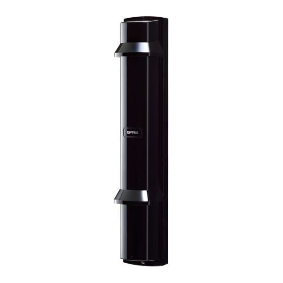
PHOTOELECTRIC DETECTOR
PHOTOELECTRIC DETECTOR
Smart Line series
Smart Line series
A photoelectric detector consists of an infrared light
source that generates IR(Infrared) beams, and an IR
receiver that detects the IR beams. The transmitter
and receiver are installed on opposite sides of the
area to be monitored. The receiver detects when the
IR beams are physically interrupted by an intruder,
and sends an alarm signal to be a control panel.
FEATURES
• Quad high power beams
• Double modulated beam
• Smart design
- Slim body design
- Easy-to-see vivid interior color for optical alignment
- IP65*
1
waterproof structure
• 4 channel beam frequency selector
• Alignment level indicator
• Viewfinder with 2X magnification
• Various options (refer to page 20)
( HU-3*
1
, ABC-4*
1
, BC-4*
• UL/c-UL Listed
CONTENTS
1
INTRODUCTION
1-1 BEFORE YOUR OPERATION ....................... 2
1-2 PRECAUTIONS....................................................... 2
1-3 PARTS IDENTIFICATION..................................... 3
2
2-1 SEPARATING................................................. 4
2-2 WIRING .......................................................... 4
2-3 TERMINAL ..................................................... 5
2-4 WIRING DIAGRAM ........................................ 5
SUPPLY AND DETECTOR ............................ 6
2-6 WALL MOUNTING ......................................... 6
2-7 POLE MOUNTING ......................................... 8
2-8 MOUNTING IN THE BEAM TOWER.............. 9
3
3-1 DIP SWITCH ................................................. 10
3-2 BEAM POWER CONTROL SELECTOR....... 10
™
™
1
, CBR-4, PSC-4*
1
, BAU-4*
1
)
*1 not evaluated by UL
*2 not require any additional tool
INSTALLATION INSTRUCTIONS
Advanced
SL-200QDP
SL-200QDM
SL-350QDP
SL-350QDM
SL-650QDP
SL-650QDM
Transmitter
• Beam interruption adjustment function
• D.Q. circuit (environmental disqualification)
• Tamper function
• Beam power control selector
• Alarm memory
• Sound assist function
- Optical alignment
- Beam reception status
- Walk test
[ SL-QDM only ]
• Auto Transmit Power Control (A.T.P.C*
• Integrated Alignment Status Communication (I.A.S.C*
communicate the transmitter and receiver
• Re-transmitting circuit function
• Solar Battery Unit SBU-4*
3-3 FUNCTION.................................................... 11
4
LOWER BEAM.............................................. 15
4-2 OPERATION CHECK.................................... 17
5
5-1 TROUBLESHOOTING .................................. 17
6
6-1 HEATER UNIT HU-3 (OPTION) .................... 18
7
7-1 DIMENSIONS ............................................... 19
8
8-1 SPECIFICATIONS......................................... 19
9
9-1 OPTIONS ...................................................... 20
-1-
UL
No.59-1881-3 131115
Detection range
Standard
60m/200ft.
100m/350ft.
200m/650ft.
2
) to optimize the beam power
2
) to
1
(option)
No.59-1881-3
Receiver
Advertisement
Table of Contents

Related Manuals for Optex Smart Line Series


Summary of Contents for Optex Smart Line Series
-
Page 1: Table Of Contents
No.59-1881-3 No.59-1881-3 131115 INSTALLATION INSTRUCTIONS Detection range PHOTOELECTRIC DETECTOR PHOTOELECTRIC DETECTOR Advanced Standard ™ Smart Line series ™ Smart Line series SL-200QDP SL-200QDM 60m/200ft. SL-350QDP SL-350QDM 100m/350ft. SL-650QDP SL-650QDM 200m/650ft. A photoelectric detector consists of an infrared light source that generates IR(Infrared) beams, and an IR receiver that detects the IR beams. -
Page 2: Before Your Operation
INTRODUCTION 1-1 BEFORE YOUR OPERATION • Read this instruction manual carefully prior to installation. • After reading, store this manual carefully in an easily accessible place for reference. • This manual uses the following warning indications for correct use of the product, harm to you or other people and damage to your assets, which are described below. -
Page 3: Parts Identification
1-3 PARTS IDENTIFICATION Cover Chassis Main unit Pole mounting Optical lens Viewfinder screw holes I.A.S.C lens [QDM only] Main unit base Mounting screw holes Horizontal alignment dial Vertical alignment dial Cut bush Wall mounting screw holes for wiring Terminals Tamper lock plate Pole mounting screw holes... -
Page 4: Installation
INSTALLATION 2-1 SEPARATING Remove the main unit from the chassis. Remove the cover. Loosen the cover lock screw. A coin (Not included) 2 Twist it lightly. Turn the optical unit 90 degrees Pull the upper part of Pull and loosen the screws (both main unit, and raise it to sides). -
Page 5: Terminal
2-3 TERMINAL SL-QDM SL-QDP <Transmitter> <Transmitter> <Receiver> <Receiver> POWER INPUT POWER INPUT (1) + (1) + (1) + (1) + POWER INPUT POWER INPUT 10.5-30VDC [ Normal ] 10.5-30VDC [ Normal ] 10.5-30VDC 10.5-30VDC (2) - (2) - (2) - (2) - 3.6VDC [ SBU-4 ] 3.6VDC [ SBU-4 ]... -
Page 6: Wiring Distance Between Power Supply And Detector
2-5 WIRING DISTANCE BETWEEN POWER SUPPLY AND DETECTOR - Ensure that the wiring distance from the power supply is within the range shown in the table below. - When using two or more units on one wire, the maximum length is obtained by dividing the wire length listed below by the number of units used. - Page 7 Fix the main unit. Insert the lower part, and then push the upper part Turn the optical unit 90 degrees and tighten the screws (both onto the chassis. sides). Make function settings and optical alignment before mounting the cover. Mount the cover and check the operation. Hook on the upper part of the chassis.
-
Page 8: Pole Mounting
2-7 POLE MOUNTING < Installing one detector > Using a screwdriver or similar tool, break the knockout position (x4) in the chassis as shown. Note>> • When mounting the single set of detectors to the pole, use a pair of the inside knockouts. The knockout positions are marked "②"... -
Page 9: Mounting In The Beam Tower
2-8 MOUNTING IN THE BEAM TOWER In accordance with the type of the main unit inside the beam tower, install the detector in the same way as wall mounting or pole mounting. < Mounting with the chassis > < Mounting without the chassis > Make function settings and optical alignment before mounting the cover. -
Page 10: Function Setting
FUNCTION SETTING 3-1 DIP SWITCH SL-QDM SL-QDP <Transmitter> <Transmitter> 4 Channel beam frequency selector switch 4 Channel beam frequency selector switch Alarm input switch [Positive/Negative] 1 2 3 <Receiver> <Receiver> 4 Channel beam frequency selector switch 4 Channel beam frequency selector switch Interruption time switch [50/100/250/500ms] Interruption time switch [50/100/250/500ms] Alarm memory switch [Auto/Manual]... -
Page 11: Function
3-3 FUNCTION SL-QDM 4 CHANNEL BEAM FREQUENCY SELECTOR SL-QDP The 4 channel beam frequency selector can be used to avoid unwanted crosstalk that can occur when using multiple photo beams for long distance or beam stacking applications. Transmitter Receiver 1 2 3 1 2 3 4 5 6 7 Channel 4 Channel 1... - Page 12 d) Perimeter protection e) Perimeter protection in a two-stack configuration Transmitter 1 Transmitter 2 Transmitter 1 Transmitter 3 Receiver 1 Receiver 3 Receiver 1 Receiver 2 Receiver 2 Receiver 1 Transmitter 4 Transmitter 3 Receiver 4 Receiver 3 Transmitter 2 Transmitter 1 Receiver 3 Receiver 4...
- Page 13 SL-QDM D.Q. (environmental disqualification) /LOW BATTERY OUTPUT SL-QDP The difference between SL-QDM and SL-QDP is as follows. SL-QDM series: Available to switch between D.Q. output and Low battery output. SL-QDP series: Only set D.Q. output. < Dip switch > Dip switch 7: D.Q./Low battery Receiver POSITION MODE...
- Page 14 SL-QDM ALARM MEMORY FUNCTION SL-QDP When an alarm is activated during alert status, the detector memorizes the alarm activation. This will allow you to check which detector activated an alarm even when multiple units are installed. In Remote mode, connect control voltage signal terminal (system arming status voltage output terminal) of control panel to ALARM MEMORY INPUT terminal (11).
-
Page 15: Optical Alignment
OPTICAL ALIGNMENT 4-1 OPTICAL ALIGNMENT FOR UPPER AND LOWER BEAM Optical alignment is an important adjustment to increase < Horizontal alignment angle > < Vertical alignment angle > reliability. Be sure to take adjustment steps 1 through 6 [ TOP VIEW ] [ SIDE VIEW ] described below to attain the maximum level of the output through the monitor jack. - Page 16 After the alignment using the viewfinder, make adjustment with the voltmeter for more accurate optical alignment. Set the voltmeter range to 5 to 10 VDC. After checking the receiving level of optical axis by using the alarm indicator, make sure to make fine alignment for both the transmitter and receiver with voltmeter to achieve a monitor output level of "Excellent".
-
Page 17: Operation Check
4-2 OPERATION CHECK Conduct a walk to check that the alarm indicator LED on the receiver turns ON or the beep sound rings on the receiver as the walker interrupts the beam. Be sure to conduct a walk test (to block the infrared beam) at the following three points: In front of the transmitter Transmitter Receiver... -
Page 18: Optional Setting
OPTION SETTING 6-1 HEATER UNIT HU-3 (OPTION) * not evaluated by UL The heat release effect makes the unit less prone to frost. HU-3 can be mounted to either upper or lower part of the unit. Use a 24 V power supply to use HU-3. <... -
Page 19: Dimensions
DIMENSIONS 7-1 DIMENSIONS 96 (3.8) Unit: mm (inch) SPECIFICATIONS 8-1 SPECIFICATIONS < SL-200QDM, SL-350QDM, SL-650QDM, SL-200QDP, SL-350QDP, SL-650QDP > ADVANCED STANDARD Model SL-200QDM SL-350QDM SL-650QDM SL-200QDP SL-350QDP SL-650QDP Maximum detection range 60 m / 200ft 100 m / 350 ft 200 m / 650 ft 60 m / 200ft 100 m / 350 ft... -
Page 20: Options
OPTEX DO BRASIL LTDA. (Brazil) OPTEX KOREA CO.,LTD. (Korea) OPTEX SECURITY SAS (France) URL: http://www.optex.net/br/es/sec/ URL: http://www.optexkorea.com/ URL: http://www.optex-security.com/ OPTEX (EUROPE) LTD. / EMEA HQ (U.K.) OPTEX (DONGGUAN) CO.,LTD. OPTEX SECURITY Sp.z o.o. (Poland) SHANGHAI OFFICE (China) URL: http://www.optexeurope.com/ URL: http://www.optex.com.pl/ URL: http://www.optexchina.com/...
Need help?
Do you have a question about the Smart Line Series and is the answer not in the manual?
Questions and answers