Table of Contents
Advertisement
Quick Links
pH/ORP Sensor
SE-pH-D/
SE-ORP-D
Thank you very much for purchasing pH/ORP Sensor SE-pH-D/
SE-ORP-D.
All of this instruction manual must be read before operation of this
pH/ORP Sensor for safe and proper operation.
This instruction manual should be kept for future reference such as
maintenance.
The instruction manual is also available on the following website.
https://navi.optex.net/manual/05330/?lang=en
Instruction
Manual
取扱説明書
Advertisement
Table of Contents

Related Manuals for Optex SE-pH-D


Summary of Contents for Optex SE-pH-D
- Page 1 Instruction SE-ORP-D Manual 取扱説明書 Thank you very much for purchasing pH/ORP Sensor SE-pH-D/ SE-ORP-D. All of this instruction manual must be read before operation of this pH/ORP Sensor for safe and proper operation. This instruction manual should be kept for future reference such as maintenance.
- Page 2 The Contents of Packaging Sensor (main unit): 1 Sensor (electrode): 1 Bushing for cable gland: 1 (Attached to sensor body cable) Instruction manual (this document) If there are any missing or faulty items, please contact our sales representative. Can be connected to SC-U1. Reference...
-
Page 3: Table Of Contents
Table of Contents For Safe Use ................5 Component Name ..............8 Electrode Attachment ............9 Installation ................11 Sensor installation ............... 11 Extension of sensor cable ........... 13 Wiring ................... 14 Sensor Setting ..............15 Display item ................ 15 Response time .............. - Page 4 10 Adjustment ................36 Offset adjustment ..............36 Span adjustment ..............38 2-point adjustment .............. 40 Adjustment initialization ............43 11 Maintenance Setting ............44 Measurement value hold ............. 44 Hold timer ................44 12 Cleaning ................45 Manual cleaning ..............45 Cleaning interval (relay) ............
-
Page 5: For Safe Use
● Please thoroughly read "For Safe Use" before using this pH/ORP Sensor properly. ● Because these precautions are related to failure or malfunction, observe the precautions for use without fail. Do not use SE-pH-D/SE-ORP-D except for measurement of water quality. " " denotes "Prohibited action", and "... - Page 6 To clean the sensor, first Do not wipe the sensor wipe away lightly with a w i t h s o l v e n t s u c h a s clean soft cloth damped Thinner. by diluted mild detergent It may cause failure.
- Page 7 ・ The electrode has an expiration date. Use in order from the oldest electrode. The date of manufacture is indicated on the sensor body (last two digits of the year + two digits of the week number) ・ When the calibration solution (standard solution) is used after immersion in the measurement water, the influence of the previous measurement Date of...
-
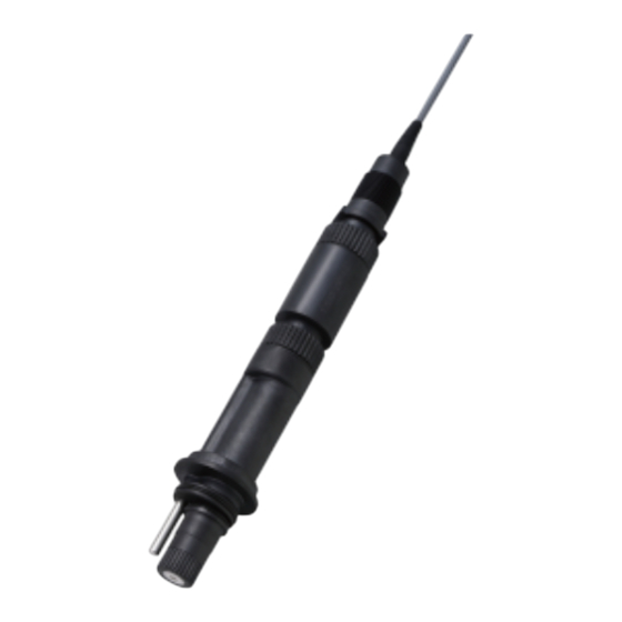
Page 8: Component Name
Component Name Electrode surface Main body Electrode... -
Page 9: Electrode Attachment
Electrode Attachment Attach the electrode just before installing the sensor. Caution Remove the cap from the electrode. ・ Do not remove the cap until just before mounting the Caution electrode. ・ Keep the removed cap for future reference. Remove the tape from the top of the cap and slide it off the electrode. Next, remove the O-ring under the cap and store it with the cap. - Page 10 Apply silicon grease to the O-ring of the electrode and attach it to the body. Attach the electrode firmly by hand. Caution Push the electrode in until it touches the connector inside the body, and then rotate it clockwise to secure it. Main body O-ring Electrode...
-
Page 11: Installation
Installation Sensor installation Before wiring, turn off the power switch of SC-U1 or disconnect the power cable from the supply source and wire the power cable after all the other wiring is complete. " " denotes "Prohibited action", and " "... - Page 12 Reference When installing the sensor in locations with high flow rates, make sure that the mounting brackets are sufficiently strong. * The PVC pipe VP-20 and a standard fitting to be prepared by the user. SC-U1 PVC pipe: VP-20 (sold separately) Use a standard fitting.
-
Page 13: Extension Of Sensor Cable
Extension of sensor cable The standard length of the sensor cable is 6 m. To extend the cable, refer to the following. To extend the cable, connection using pull box is recommended. Max. cable length 1200 m (nominal cross-sectional area of 0.2 to 1.25 mm2) Pull box, etc. -
Page 14: Wiring
Wiring Use this product by connecting to Universal Transmitter SC-U1. For installation and wiring to SC-U1, refer to the "Universal Transmitter SC-U1 Installation Manual". Before wiring, turn off the power switch of SC-U1 or disconnect the power cable from the supply source and wire the power cable after all the other wiring is complete. -
Page 15: Sensor Setting
Sensor Setting The following settings are available from SC-U1. To start sensor setting, press Caution Pressing automatically retains the measurement value. Display item Set items to display as main, 2nd, and 3rd display of SC-U1. Main display 2nd display 3rd display Select an item from the following. -
Page 16: Response Time
Display item Measurement Factory default item setting Item Unit Main display pH 2nd display Temperature Temperature °C Temperature – – 3rd display – – Electromotive force pH mV Main display ORP Response time Set a signal output response time. A measurement value is calculated using moving average of the time period set by the signal output response time. - Page 17 Factory default Model Measurement item setting Calibration Auto Auto mode Manual None – Press The setting menu is displayed. Select [Sensor Setting] using , and press Select [Calibration Mode] using , and press Select [Auto] or [Manual] using , and press...
-
Page 18: Calibration Standard Selection
Calibration standard selection Set the standard to be complied with during calibration. This setting is effective for pH measurement. It does not affect Caution ORP measurement. Factory default Model Measurement item setting Calibration standard HAMILTON DIN19267 Merck/Riedel Mettler – – Press The setting menu is displayed. -
Page 19: Selection Of 1St/2Nd Points Standard Solution
Select the calibration standard to be set using , and press Selection of 1st/2nd points standard solution Set the pH value of the calibration solution (standard solution) to be used for calibration. Set the 1st and 2nd points individually. In 1-point calibration, span errors can be minimized by using a calibration solution (standard solution) that is close to the expected pH value of the measurement water. - Page 20 Press The setting menu is displayed. Select [Sensor Setting] using , and press Select [1st standard solution] or [2nd standard solution] using , and press Select the pH value using and press [1st standard solution] selected [2nd standard solution] selected...
-
Page 21: 4-20 Ma Setting
4-20 mA Setting Set the 4-20 mA signal output setting from SC-U1. The factory default setting is OFF for 4-20 mA signal output. To set 4-20 mA output setting, press Caution Pressing automatically retains the measurement value. Output item selection Select an item to output by 4-20 mA signal. -
Page 22: Upper/Lower Limit Of Signal Output Range
Upper/lower limit of signal output range For the item by 4-20 mA signal output, set measurement value to output at lower limit (Lo, 4 mA) and upper limit (Hi, 20 mA). 20 mA Signal output 4 mA Measurement Measurement value at 4 mA value at 20 mA For operation, refer to the "Universal Transmitter SC-U1 Operation Manual", "6.3 4-20 mA Setting", "... -
Page 23: Relay Setting
Relay Setting Set the relay output setting from SC-U1. The factory default setting is OFF for relay output. To set the relay setting, press Caution Pressing automatically retains the measurement value. Alarm output setting Set the alarm to be output when the measurement value exceeds a certain value. -
Page 24: Cleaning Output Setting
Output item Electromotive Setting item pH: pH Temperature force [pH] [ORP] [Temperature] [Electromotive force] Trigger High Alarm/Low Alarm Active Level 0.00 to 14.00 0.0 to 60.0°C: -500.00 to -1500 to In units of 500.00 mV: 1500 mV: 0.1°C In units of In units of In units of 0.01 pH... -
Page 25: Calibration (Ph Only)
Calibration (pH only) In pH measurement using the glass electrode method, reliable data can be obtained only when the pH at the sensor location, the performance of the electrode, and the accuracy of the calibration solution (standard solution) are combined. There are two types of pH calibration methods: automatic calibration and manual calibration. - Page 26 Select a channel connected to SE-pH-D using , and press The calibration menu is displayed. Sensor model Measurement item Sensor channel Select [1-Point Calibration] using , and press Press When the calibration mode is Auto, calibration starts automatically when the value is stabilized.
- Page 27 Check the results after calibration is completed. good: The calibration is properly completed. good E4500 to E4802: Calibration failed. E4500 Try the steps again from 1. poor: Asymmetric potential error. poor Try the steps again from 1. Press to return to the measurement display. For error display, refer to "Error code list"...
-
Page 28: 1-Point Calibration (Calibration Mode: Manual)
Press The sensor selection display is displayed. Select a channel connected to SE-pH-D using , and press The calibration menu is displayed. Sensor model Measurement item Sensor channel... - Page 29 Check that the value is stable and press Calibration starts. When the calibration is completed, the progress bar is displayed and then the calibration result is displayed. Check the results after calibration is completed. good: The calibration is properly completed. good E4500 to E4802: Calibration failed.
-
Page 30: 2-Point Calibration (Calibration Mode: Auto)
(standard solution) for about 5 minutes with little change in temperature, then check that there are no bubbles on the electrode surface. Press The sensor selection display is displayed. Select a channel connected to SE-pH-D using , and press The calibration menu is displayed. Sensor model Measurement item... - Page 31 After immersing the sensor in the 1st calibration solution (standard solution), select [2-point Calibration] using , and press Press When the calibration mode is set to Auto, calibration starts automatically when the measurement value is stabilized. Clean the electrode surface before immersing in the 2nd calibration solution (standard solution).
- Page 32 When the calibration is completed, the progress bar is displayed and then the calibration result is displayed. Check the results after calibration is completed. good: The calibration is properly completed. good E4500 to E4802: Calibration failed. E4500 Try the steps again from 1. poor: Asymmetric potential error.
-
Page 33: 2-Point Calibration (Calibration Mode: Auto)
(standard solution) for about 5 minutes with little change in temperature, then check that there are no bubbles on the electrode surface. Press The sensor selection display is displayed. Select a channel connected to SE-pH-D using , and press The calibration menu is displayed. Sensor model Measurement item... - Page 34 After immersing the sensor in the 1st calibration solution (standard solution), select [2-Point Calibration] using , and press Check that the measurement value is stable and press Immerse the sensor in the 2nd calibration solution (standard solution), and after the measurement value is stabilized, press start the 2nd calibration.
-
Page 35: Calibration Initialization
Check the results after calibration is completed. good: The calibration is properly completed. good E4500 to E4802: Calibration failed. E4500 Try the steps again from 1. poor: Asymmetric potential error. poor Try the steps again from 1. Press to return to the measurement display. For error display, refer to "Error code list"... -
Page 36: Adjustment
Adjustment Adjust and display the measurement values according to usage. In addition, adjust and display the measurement values according to the environment where used. Electromotive force cannot be adjusted. To adjust, press ・ Pressing automatically retains the measurement value. ・ If offset, span, or 2-point adjustment has already been performed, be sure to initialize the adjustment before performing the 2-point adjustment. - Page 37 to select the item for offset adjustment and press to switch pages. Sensor model The adjustment menu is displayed. Output item Sensor channel Select [Offset Adjustment] using , and press Enter the offset value. Select a digit by and value , and press When a value outside the set range is entered, a short beep sounds.
-
Page 38: Span Adjustment
Span adjustment Set the span coefficient for a measurement value. Display value after span Display the measurement value with adjustment span-adjusted to any display value. Measurement For 4-20 mA output ("7 4-20 mA Setting" P.21) value and alarm output ("Alarm output setting" P.23), the adjusted values are applied. - Page 39 Select [Span Adjustment] using , and press Input a span adjustment value. Select a digit by and value , and press When a value outside the set range is entered, a short beep sounds. Pressing simultaneously while entering a value resets the value to the factory default setting.
-
Page 40: 2-Point Adjustment
2-point adjustment Display current values of the 2 points as any adjustment values, respectively. Performing 2-point adjustment changes the offset and span based on the adjusted values. For 4-20 mA output ("7 4-20 mA Setting" P.21) and alarm output ("Cleaning output setting" P.23), the adjusted values are applied. - Page 41 Press The measurement item selection display is displayed. Select an item to perform the 2-point adjustment using , and press to switch pages. Sensor model Output item The adjustment menu is displayed. Sensor channel Select [2-Point Adjustment] using , and press...
- Page 42 Enter the [Point 1] display, [Point 1] adjusted, [Point 2] display, and [Point 2] adjusted values in this order. Select a digit by and value by , and press . The value is set and the cursor moves to the next item. When a value outside the set range is entered, a short beep sounds.
-
Page 43: Adjustment Initialization
Adjustment initialization Reset the adjustment value to the factory default value. Press The measurement item selection display is displayed. Select an item to initialize adjustment using , and press to switch pages. Sensor model Output item The adjustment menu is displayed. Sensor channel Select [Initialize Adjustment Value] using... -
Page 44: Maintenance Setting
Maintenance Setting Set the maintenance setting from SC-U1. To perform maintenance, press Caution Pressing automatically retains the measurement value. Measurement value hold The latest measurement value is retained (held). This is used for sensor maintenance and cleaning. For operation, refer to the "Universal Transmitter SC-U1 Operation Manual", "8 Maintenance Setting"... -
Page 45: Cleaning
While cleaning the measurement value of the target sensor is retained (held). Press The sensor selection display is displayed. Select a channel connected to SE-pH-D/SE-ORP-D using and press By selecting [ALL], all of the connected Output Sensor... -
Page 46: Cleaning Interval (Relay)
Select [Manual Cleaning] using , and press The cleaning device is activated and the display returns to the measurement value display. The sensor under cleaning shows "CLEAN" on the measurement value display. In addition, "C" is displayed in the sensor selection display. Cleaning interval (relay) Set a time interval to activate the cleaning device. -
Page 47: Cleaning Activation
Cleaning activation Set the time period for cleaning. Select an item from the following. For operation, refer to the "Universal Transmitter SC-U1 Operation Manual", "9 Cleaning" and " ◆ Cleaning Activation". Factory Item Setting range default setting Cleaning Activation 10 to 120 seconds (by 10 seconds) 30 seconds Post-cleaning standby Set the standby time after cleaning. -
Page 48: Troubleshooting
Troubleshooting Error code list The following table describes error codes, causes and actions. If you find any problem other than the error codes, refer to "When in trouble" in the "Universal Transmitter SC-U1 Operation Manual". When the normal condition is not recovered after the countermeasure is taken, when any problem other than these occurs, or when requesting repairs, check the model and the serial No. - Page 49 Error code and details Cause Action E4601 The sensitivity The electrode must Electrode sensitivity error of the pH be repaired. Refer to sensor may be "Electrode replacement" degraded. P.52. E4601 The calibration Prepare a calibration solution (standard solution (standard solution) used for solution) with the correct the 1st point or pH value.
- Page 50 Error code and details Cause Action E4700 Bubbles and Clean the electrode Asymmetric potential error dirt adhere to surface and perform the the electrode calibration again. If an surface. error occurs after cleaning E4700 and calibration again, the electrode must be replaced. Refer to "Electrode replacement"...
- Page 51 If the measurement result is poor as shown below, the calibration has been completed. However, take appropriate measures as Caution soon as possible because it may not be possible to measure correctly. Error code and details Cause Action poor The sensitivity The electrode must Electrode sensitivity error of the pH...
-
Page 52: Maintenance
Maintenance ・ To clean the sensor, lightly wipe with a clean, soft cloth and water Caution diluted with a mild detergent, and then wipe with a dry, soft cloth. ・ Do not wipe the sensor with organic solvent such as benzine. Maintenance (monthly) Perform the following operations every month. -
Page 53: Cleaning Tips
Cleaning tips If the measurement surface of the sensor is covered with a coating, incorrect readings may occur, such as a shortened span or a slower response time. Clean according to the type of coating. ・ Soft coatings can be removed by vigorous agitation, flushing with a spray bottle, or carefully wiping with soft, clean, non-abrasive paper or cloth. -
Page 54: Specifications
Specifications Model SE-pH-D SE-ORP-D Measurement pH/temperature ORP (Oxidation item reduction potential) Measurement 0.00 to 14.00 pH -1500 to 1500 mV range Temperature 0.0 to 60.0°C Electromotive -500.00 to force 500.00 mV Display 0.01 pH 1 mV resolution Temperature 0.1°C Electromotive 0.01 mV... -
Page 55: External Dimensions
External Dimensions NPT 3/4... - Page 56 OPTEX CO., LTD. 5-8-12, Ogoto, Otsu, Shiga, 520-0101 Japan el.+81-77-579-8680 Fax.+81-77-579-8199 http://www.optex.co.jp/env/eng/ 2022.11 59-3150-1...
Need help?
Do you have a question about the SE-pH-D and is the answer not in the manual?
Questions and answers