Table of Contents
Advertisement
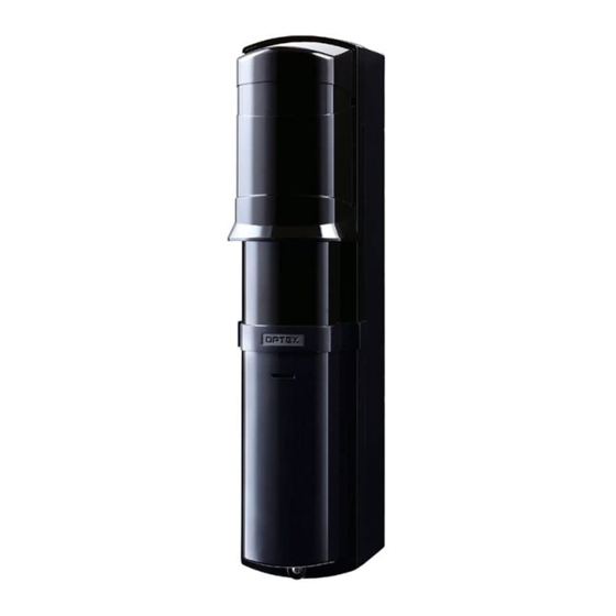
BATTERY OPERATED
BATTERY OPERATED
PHOTOELECTRIC DETECTOR
PHOTOELECTRIC DETECTOR
Smart Line series
Smart Line series
FEATURES
• Battery operated detector
- D size lithium battery or CR123A lithium battery
(OPTION CRH-5)
• Simplified optical adjustment
- Sniper View Finder with ×2 magnification
• Avoids having to install a wireless transmitter in the
photoelectric transmitter.
- IR signal transmission technology transfers the low
battery signal to the receiver
• Possible to connect the power and alarm cables to both
the receiver and the transmitter or either of them
- OPTION PCU-5
CONTENTS
1 INTRODUCTION
1-1 BEFORE YOUR OPERATION ............................... 2
1-2 PRECAUTIONS...................................................... 3
1-3 PARTS IDENTIFICATION ...................................... 3
2 PREPARATIONS ......................................................... 4
3 INSTALLATION
3-1 SEPARATING ........................................................ 5
3-2 WALL MOUNTING ................................................ 5
3-3 POLE MOUNTING ................................................. 8
3-4 MOUNTING EXAMPLE AT PARTICULAR CASE.. 9
3-5 WIRING .................................................................. 9
INSTALLATION INSTRUCTIONS
™
™
MODEL
SL-100 TNR
SL-200 TNR
• Long battery life
• Battery saving function
• Intermittent output function
• Slim body design
• Easy to see vivid interior color for optical alignment
• IP65 waterproof structure
• Tamper function
• Indicator LED for an easy alignment
• Various options (Refer to "2 PREPARATIONS" and
"9 OPTIONS").)
(CRH-5, BCU-5, PCU-5)
4 SETTINGS
4-1 FUNCTIONS......................................................... 11
4-2 OPTICAL ALIGNMENT ........................................ 12
5 OPERATION CHECK
5-1 LED INDICATION................................................. 13
5-2 OPERATION CHECK........................................... 13
6 TROUBLESHOOTING ............................................... 14
7 DIMENSIONS............................................................. 14
8 SPECIFICATIONS ..................................................... 15
9 OPTIONS ................................................................... 16
EN-1
No.59-2606-0 1612-16
DETECTION RANGE
30 m / 100 ft.
60 m / 200 ft.
Advertisement
Table of Contents

Related Manuals for Optex SL-100 TNR


Summary of Contents for Optex SL-100 TNR
- Page 1 PHOTOELECTRIC DETECTOR Smart Line series Smart Line series ™ ™ MODEL DETECTION RANGE SL-100 TNR 30 m / 100 ft. SL-200 TNR 60 m / 200 ft. FEATURES • Battery operated detector • Long battery life - D size lithium battery or CR123A lithium battery •...
-
Page 2: Introduction 1-1 Before Your Operation
INTRODUCTION BEFORE YOUR OPERATION • Read this instruction manual carefully prior to installation. • After reading, store this manual carefully in an easily accessible place for reference. • This manual uses the following warning indications for correct use of the product, harm to you or other people and damage to your assets, which are described below. -
Page 3: Precautions
PRECAUTIONS Do not install the unit on Do not install the pole in a Do not install the unit in Do not install the receiver an unstable surface. location where sufficient trees, leaves, or other in a location where it is stability can not be objects that may swing in exposed to direct sunlight. -
Page 4: Preparations
Accessories 4×20 self tapping for wall mounting Velcro tape: 1 set Cables: 3 (with rubber washer): 4 M4×16 screws for pole mounting Pole brackets: 2 U-brackets: 2 (with rubber washer): 4 PREPARATIONS = depends on each type of the wireless transmitter 1. -
Page 5: Installation 3-1 Separating
INSTALLATION SEPARATING Remove the main unit cover. Remove the connectors. Remove the battery cover. Loosen the Pull Loosen the Pull battery cover main unit cover lock screw. lock screw. Remove the main unit from the back box. Turn the optical unit Take the main unit out of the back box. - Page 6 Mount the back box to the wall. Side wall Distance from the side wall: at least 1m Pitch: 83.5 mm For connection to gang electric 4×20 self tapping (with rubber washer) Using Velcro tape, fix the wireless transmitters in the back box. For more information on wiring, see “3-5 WIRING”.
- Page 7 Attach the connectors. Note>> • Avoid placing the cables in a position where they can be caught between the main unit and cover. Insert batteries. • Apply the same procedure for the battery replacement. < When using D size battery > 1 Open the battery plate in the direction of the arrow.
-
Page 8: Pole Mounting
Close the main unit cover. Close the battery cover. Hook on the upper part Close the battery cover. of the back box. Push the lower part of the main unit cover. Tighten the fixing screw for the battery cover. Fasten the main unit cover lock screw. -
Page 9: Mounting Example At Particular Case
Fix the back box on the pole. Detector No. 2 Pole bracket U-bracket Detector No. 1 Side wall Distance from the side wall: at least 1m M4×20 screw (with rubber washer) Pole 43 to 48 mm dia. (1.69 to 1.89 inch dia.) Perform the same procedure as 3 to 9 of "3-2 WALL MOUNTING". - Page 10 When connecting to BCU-5 (OPTION) BCU-5 allows to share power source and low battery signals between the main unit and the wireless transmitter. For more information on connecting, see BCU-5 manual. Main unit Back box BCU-5 Receiver Battery Black Plate EX EX –...
-
Page 11: Settings 4-1 Functions
SETTINGS FUNCTIONS DIP SWITCH Refer to “1-3 PARTS IDENTIFICATION”. Beam interruption adjustment switch 1 Beam interruption adjustment switch 2 Battery saving timer switch Receiver Intermittent output function switch Note>> SELECTOR • Do not press the tamper when you set the DIP POSITION switches. -
Page 12: Optical Alignment
OPTICAL ALIGNMENT Optical alignment is an important procedure to increase reliability. Be sure to take alignment step 1 through 2 described below to attain the maximum level of the output through the monitor jack. Horizontal alignment angle Vertical alignment angle 5°... -
Page 13: Operation Check 5-1 Led Indication
OPERATION CHECK LED INDICATION Alarm/Level indicator LED (Receiver only) Note>> • The operation of the Alarm/Level indicator LED will not be changed by the battery saving timer setting. Whenever the beam is interrupted, the indicator will turn ON. DETECTOR Alarm/Level indicator Beam Interruption ON (continue) -
Page 14: Troubleshooting
TROUBLESHOOTING Reversed battery polarity. Check the battery polarity. Power/Low battery indicator LEDs are not illuminated. (transmitter/receiver) Batteries are run or running out. Replace all batteries. Alarm is not output. Beam has not been blocked. Block all two beams. indicator LED is illuminated but the alarm Signal line short-circuited Check the wiring. -
Page 15: Specifications
SPECIFICATIONS Model . t f 60 m/200 ft. . t f 530 m/1740 ft. Detection method Twin infrared beam interruption detection Interruption time Selectable from 50/100/250/500 ms (4 selections) 3.6 to 3.9VDC D size lithium batteries Each Transmitter and Receiver: 2 units (Recommended SB-D02HP manufactured by VITZROCELL) Power source 3.0 VDC... -
Page 16: Option Crh
OPTEX SECURITY Sp.z o.o. (Poland) OPTEX (DONGGUAN) CO.,LTD. URL: http://www.optex.net/br/es/sec URL: http://www.optex.com.pl SHANGHAI OFFICE (China) URL: http://www.optexchina.com OPTEX (EUROPE) LTD. / EMEA HQ (U.K.) OPTEX PINNACLE INDIA, PVT., LTD. (India) URL: http://www.optex-europe.com URL: http://www.optex.net/in/en/sec OPTEX (Thailand) CO., LTD. (Thailand) URL: http://www.optex.net/th/th OPTEX TECHNOLOGIES B.V.(The Netherlands)
Need help?
Do you have a question about the SL-100 TNR and is the answer not in the manual?
Questions and answers