Table of Contents
Advertisement
Quick Links
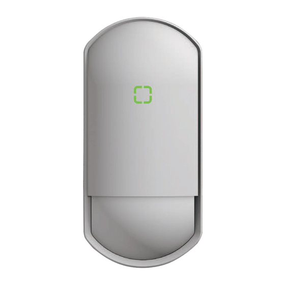
Flexible Range Indoor Detector
Flexible Range Indoor Detector
FlipX series
FlipX series
STANDARD MODELS
<< Contents >>
Page
1
3
4
2
3
10
Others
11
12
12
13
with bracket CW-G2
13
Wide/Narrow area
FLX-S-ST
FLX-S-ST-BKT*3
FLX-S-DT-X5*1
FLX-S-DT-X5-BKT*3
FLX-S-DT-X8*2
FLX-S-DT-X9*3
*1 Not certified to INCERT
*2 Not certified to SBSC and UL
*3 Not certified to EN 50131-2-2 :2017 (FLX-S-ST-BKT)/EN 50131-2-4:2020 (FLX-S-DT-X5-BKT/X9),
INCERT, SBSC and UL
2
3
Ceiling
mount
5
with bracket
with bracket
7
8
8
1
INSTALLATION INSTRUCTIONS
PIR
Microwave
Flip lens
✓
✓
✓
✓
✓
✓
✓(10.525GHz)
✓
✓
✓(10.525GHz)
✓
✓
✓(10.587GHz)
✓
✓
✓(9.425GHz)
6
No.59-3043-0 2201-27
UL No.59-3043-0 2104-12
EN
Mounting bracket
-
-
-
✓
-
✓
-
-
Advertisement
Table of Contents

Subscribe to Our Youtube Channel
Related Manuals for Optex FLX-S-ST


Summary of Contents for Optex FLX-S-ST
-
Page 1: Table Of Contents
FLX-S-DT-X9*3 ✓ ✓ ✓(9.425GHz) *1 Not certified to INCERT *2 Not certified to SBSC and UL *3 Not certified to EN 50131-2-2 :2017 (FLX-S-ST-BKT)/EN 50131-2-4:2020 (FLX-S-DT-X5-BKT/X9), << Contents >> INCERT, SBSC and UL Before installation Page - Manufacturer’ s statement... -
Page 2: Before Installation
Before installation - Manufacturer’ s statement Symbol Meaning Symbol Meaning Check mark indicates recommendation. Failure to follow the instructions provided with this indication Warning Nix sign indicates prohibition. and improper handling may cause death or serious injury. Failure to follow the instructions provided with this indication Special attention is required to the Caution NOTE... -
Page 3: Parts Identification
- Parts identifications Base Sponge Main unit Option CW-G2 Cover Bracket for wall/ceiling mount NOTE Models with “-BKT” in the model name include CW-G2. Joint screw x 3 Fixing screw x 2 Lens *Not certified to EN 50131-2-2:2017 /EN 50131-2-4:2020, INCERT and SBSC Installation 1-1. -
Page 4: Wall Mount
1-2. Wall mount without bracket How to break the knockouts Wire through the base Wiring knockouts For Wall/ Corner mount Surface wiring : Upper For Wall/ Corner mount : Lower Hidden wiring: A. Surface wiring B. Hidden wiring A-1. Upper A-2. -
Page 5: Wall
1-3. Wall mount with bracket Wire and mount on the wall Wiring knockout guide Punch out 3 knockout guides to open NOTE the wiring hole to allow wire run. Mounting screws are not included. Φ 3 mm screws are recommended. Wiring knockout hole NOTE... - Page 6 1-4. Ceiling mount with bracket How to change the bracket to the ceiling mounting [1] Loosen the fixing screw. [2] Rotate the body. [3] Tighten the fixing screw. WALL CEILING Rear side Rear side WALL CEILING Wire and mount on the ceiling Wiring knockout guide Punch out 3 knockout guides to open...
-
Page 7: Assemble And Connect
[1] Hook the top of the PCB on the protrusions on both sides. [2] Push the bottom of the PCB over the protruding claws. Connect wires to the terminal Power Spare Alarm Tamper ALARM TAMP Remote FLX-S-ST N.C. N.C. +12 V - (Normally Close) SP LED ALARM TAMP FLX-S-DT N.C. -
Page 8: Settings
Settings 2-1. Jumper pin settings LENS MW SHORT LONG Wide/Narrow MW sensitivity (FLX-S-DT only) ON OFF LED SENS PIR sensitivity H: High sensitivity M: Medium sensitivity Low sensitivity (Pet immunity mode; ON: LED is activated always. Not certified to EN, OFF: LED can be controlled through the INCERT and SBSC) - Page 9 How to remove the lens Get over the rib, then pull up the lens. Caution Be careful not to damage the light path of the LED. Also, be careful not to allow the light path to pinch the wiring when closing the cover. If it is difficult to get over, use a flathead screwdriver.
-
Page 10: Checking
Checking 3-1. Walk test Confirm that the LED pin is “ON” , then close the cover. Walk in the detection area to check the detecting performance via LED indication. ON OFF LED Return the LED pin to “OFF” after the walk test, if necessary. Lock the cover ON OFF LED (optional) -
Page 11: Specifications
Others - Specifications Model FLX-S-ST (-BKT) FLX-S-DT-X5(-BKT)/-X8/-X9 Installation Detection method Passive infrared Passive infrared and Microwave Wide : 12 m (40 ft.) 85°/ Narrow : 18 m (60 ft.) 5° Coverage ( No MW detection at “Narrow” setting ) Detection zones... -
Page 12: Dimensions
9 ft. dotted line indicates the recommended mounting height. 12 m When “Narrow” is selected at the jumper pin, detection will be stopped. Narrow area settings are certified to the following standards. EN 50131-2-2:2017 (FLX-S-ST)/EN 50131-2-4:2020 (FLX-S-DT), INCERT and SBSC. -
Page 13: Angle Adjustment
+5°. - Compliance RE Directive 2014/53/EU OPTEX declares that FLX-S-DT-X5, FLX-S-DT-X5-BKT, FLX-S-DT-X8, and FLX-S-DT-X9 comply with RE Directive 2014/53/EU. ■ Doc documents can be found on our website; www.optex.net Microwave emission Frequency and Power ■...
Need help?
Do you have a question about the FLX-S-ST and is the answer not in the manual?
Questions and answers