Table of Contents
Advertisement
Advertisement
Table of Contents

Related Manuals for Ablerex ODIN


Summary of Contents for Ablerex ODIN
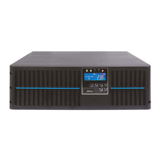
- Page 1 ODIN Parallel Redundancy On-Line UPS 6K/10KVA User’s Manual...
-
Page 2: Table Of Contents
Table of Contents Important Safety Instruction ................2 1.1. An Important Notice ..................2 1.2. Storage Instruction .................... 4 Product Introduction ..................5 2.1. General Characteristics ..................5 2.2. Symbols on the LCD Display Panel ..............7 2.3. Panel explanation .................... 10 2.4. -
Page 3: Important Safety Instruction
1. Important Safety Instruction 1.1. An Important Notice For Parallel System installation, please refer to “6/10KVA Parallel System 1.1.1. Installation Guide” 1.1.2. This UPS is equipped with an EMI filter. To prevent potential leakage current hazard, ensure that the AC main supply is securely grounded. 1.1.3. - Page 4 1.1.14. Dusty, corrosive and salty environments can do damage to any UPS. 1.1.15. Install the UPS away from objects that give off excessive heat and areas that are excessively wet. 1.1.16. If liquids are split onto the UPS or foreign objects dropped into the unit, the warranty will be null and void.
-
Page 5: Storage Instruction
1.1.24. This UPS has been designed and constructed to protect your assets from the wide range of power aberrations experienced on Utility power lines today. It is your insurance for reliable, clean and stable voltage supply. It is worth taking care to install the system correctly and to have it maintained correctly by your local dealer. -
Page 6: Product Introduction
2. Product Introduction 2.1. General Characteristics 2.1.1. True online architecture continuously supplies in your critical device with a stable, regulated, transient-free pure sine wave AC Power. 2.1.2. 20KHz PWM sine-wave topology yields an excellent overall performance. The high crest factor of the inverter handles all high-inrush current loads without a need to upgrade the power rating. - Page 7 2.1.12. Revolutionary battery management circuit analyzes battery discharging status to adjust battery cut-off point and extend the life of batteries. 2.1.13. Intelligent temperature-controlled fan may not only extend the life of the fan, but also reduce annoying noise because of sudden fan spin. It remains your office quiet and comfortable as usual.
-
Page 8: Symbols On The Lcd Display Panel
2.2. Symbols on the LCD Display Panel Item Symbol Description LINE Utility or Bypass Source Battery Low Battery Abnormal UPS Overloading UPS Working in specified mode* A Blackout Transfer occurred in UPS Output Bypass Input Abnormal, UPS fails to transfer to bypass, Bypass Abnormal at ECO mode Utility Input Abnormal UPS Shutoff... - Page 9 Next Page Special Function Log in /out Enter or Reconfirmed Utility Input Normal LED Bypass Input Normal LED UPS under Redundancy Mode UPS under ECO Mode UPS Fault or Abnormal Warning LED Emergency Power Off Er05 Battery Weak or Dead Er06 Output Short Circuit Er10...
- Page 10 Parallel communication error ( communication Er21 wire disconnected or failure to find ID1 UPS ) in parallel system Er24 CVCF mode with Bypass input The UPS must be operated in normal mode in Er27 parallel system Er28 Bypass Overload Time out and cut off output. The settings of both control board and driver Er31 board are not matched each other.
-
Page 11: Panel Explanation
2.3. Panel explanation 2.3.1. Front Panel Function Explanations LCD Display Green LED lights up to indicate the UPS has the capability to run under redundancy mode. Green LED steadily lights up to indicate that the Utility input voltage is within the window;... - Page 12 2.3.2. Rear Panel Explanation UTILITY INPUT BREAKER BYPASS INPUT BREAKER SLOT 10KVA UTILITY INPUT BREAKER 6KVA SLOT OUTPUT INPUT N 2 2 L 2 1 L 1 2 A RS232 Port B Terminal Resistor for Parallel function C CAN Bus Connection Port for Parallel System D Customer Options Slot F Cooling Fan G External Battery Connector...
-
Page 13: Communication Port Explanation
2.4. Communication Port Explanation The Communication port on the UPS provides true RS232 type to communicate with UPS software to remote monitoring the power and UPS status. With optional interfaces cards, which contains R2E(2 RS232), RSE(RS485), USE(USB), DCE(Dry Contact), as well as SNMP/ card, you may combine them according to your demand. -
Page 14: Installation And Operation
3. Installation and Operation The packing condition and the external outlook of the unit should be inspected carefully before installation. Retain the packing material for future use. 3.1. Unpacking 3.1.1. Take the UPS out of the PE foam. 3.1.2. Unwrap the UPS. 3.1.3. -
Page 15: Selecting Installation Position
3.2. Selecting Installation Position It is necessary to select a proper environment to install the unit, in order to minimize the possibility of damage to the UPS and extend the life of the UPS. Please follow the advice below: 1. Keep at least 30cm (12 inches) clearance from the rear panel of the UPS to the wall. -
Page 16: Terminal Block Explanation
3.4. Terminal Block Explanation EVOLPACK 6KVA EVOLPACK 10KVA... - Page 17 L12-N1: the terminal for Utility Input to provide the power source when the UPS ● is working under Utility mode. G1: the terminal for UPS Input Ground. ● L21、N22: the terminals for UPS Output. ● G2: the terminal for UPS Output Ground. ●...
- Page 18 Use Mounting Cable Tie to fix cables. ● EVOLPACK 6KVA EVOLPACK10KVA 6. Please refer to the specs of input current, output current and recommended conductors listed as below: a. AC input and output (75C minimum copper wire) Model Maximum Current Conductor Torque force Section...
-
Page 19: Operation Test And Installation Instruction
3.5. Operation Test and Installation Instruction 3.5.1. Start Up in Normal Mode 3.5.1.1. Open the terminal block cover on the rear panel (refer to 2.3.2) Before start the installation, please make sure the grounding is connected properly. Make sure Utility breaker, UPS’ Utility breaker and Bypass breaker are 3.5.1.2. - Page 20 3.5.1.5. Then, the UPS is on Bypass Mode now and it will proceed self-test automatically. If there is no abnormal message occurred, it means the pre-startup of the UPS is successful and the charger starts to charge the batteries. 3.5.1.6. Press the UPS On Switch for approx.
- Page 21 * It shows “220Vac or 208Vac” in Utility Input. 3.5.1.8. In case of failure in self-test, the LCD display will illustrate from Drawing D to drawing E2, then an error code or error status will be shown on the screen. 3.5.1.9.
- Page 22 * It shows Utility input is “0” and Utility Abnormal. 3.5.3. Check Measured Values & Figures detected by UPS 3.5.3.1. If you would like to check the measured values & figures detected by the UPS, please use scroll up and scroll down key pads.
- Page 23 * It shows frequency from Utility Input 50 Hz or 60 Hz.. * It shows frequency from Bypass Input. * It shows UPS output Voltage 120 Vac or 220 Vac. * It shows UPS output frequency 50 Hz or 60 Hz. * It shows UPS output load level(%)
- Page 24 * It shows Battery Voltage. * It shows UPS Inner Temperature 3.5.4. UPS Default Data and Special Function Execution 3.5.4.1. After UPS completely starts up, press key pad to change the LCD display screen to drawing Q1. * It shows buzzer “On”. * It shows buzzer “Off”.
- Page 25 3.5.4.2. Press key pad to scroll down the screen and check the UPS settings. The LCD display will show in consequence between Drawing Q1(buzzer) Drawing R1(Self-test) Drawing S1(Bypass Voltage Windows) Drawing T(Output Frequency Synchronization Window) Drawing U(Inverter Output Voltage) Drawing V1(UPS Operation Mode) Drawing W(Output Voltage Micro Tune Value) Drawing X(UPS Id) Drawing Y(Parallel function status).
- Page 26 * It shows Frequency Window is +/-3Hz. * It shows inverter output voltage. * It shows the UPS is operated in “normal mode”. * It shows the UPS is operated in “Eco mode”. * It shows the UPS is operated in “CVCF 50Hz mode”.
- Page 27 * It shows the UPS is operated in “CVCF 60Hz mode”. * It shows Output Voltage Adjustment % from 0% to 3% or -0% to -3%. * It shows UPS Identification Number. * It shows the UPS is in the No. 1 of parallel systems.
- Page 28 3.5.4.4. 3.5.5. UPS Default Settings and their alternatives Make sure the UPS is not “On” yet. Press On Switch 3.5.5.1. and scroll down key pads simultaneously for approx. 3 seconds, the buzzer will sound twice, the LCD display screen shows as drawing Q1, then the UPS is under setting mode now.
- Page 29 * It shows the UPS is locked. 3.5.5.12. Turn Off the breaker of Utility Input. 3.5.5.13. Your Setting changes are complete. 3.5.6. UPS Is Off Due to Unknown Reason and Its Trouble Shooting 3.5.6.1. If there is a serious abnormal condition occurred, the UPS will lock it itself in “OFF”...
- Page 30 3.5.8.1. It is for UPS maintenance only. A Non-authorized technician is not allowed to operate the following procedures. If there is any damage under unauthorized condition, your warranty will be void immediately. 3.5.8.1.1. Press the Off key pad for approx. 5 seconds, the LCD screen shows as drawing B and the UPS output is on bypass mode.
-
Page 31: Troubleshooting Guide
4. Troubleshooting Guide 4.1. Trouble Shooting When the UPS malfunctions during operation, you may check the followings: a. Are the wirings of input and output correct? b. If the input voltage of the Utility is within the input window of the UPS? In case problems or symptoms still exist, please proceed the followings for proper adjustment. - Page 32 Situation Check Items Solution UPS Red Fault Check the error code Check to see if the battery LED lights up shown on the LCD screen connection is properly done, then re-charge the batteries for 8 hours to see whether the UPS may backup Er05, normally;...
- Page 33 UPS locks Please refer to chapter 3.5.6 to trouble itself and it can shoot the problem; otherwise, consult your not be turned local distributor for help. off.
-
Page 34: Bundled Software Installation Guide
5. Bundled Software Installation Guide 5.1. Hardware Installation 1. Connect the male connector of RS232 cable to the UPS communication port. 2. Connect the female connector of the RS232 cable to a dedicated RS232 port of the computer. 3. For optional interface cards, you may refer to Chapter 6 for installation. Software Installation 5.2. -
Page 35: Customer Options Slots
6. Customer Options Slots 6.1. R2E(2nd RS-232 ) card 6.1.1. CN1 is for RS232 DB9. 6.1.2. For communication protocol, please refer to Chapter 2.4.1 6.2. RSE(RS-485) card 6.2.1. CN1 is for the function of the terminal resistor. Short pin1-2 to enable the function and short pin2-3 to disable it. 6.2.2. -
Page 36: Dce(Dry Contact)-B Card
1 VCC (+5V) 2 D- 3 D+ 4 Ground 6.4. DCE(Dry Contact)-B card 6.4.1. The pin assignments of 10-Pin Terminal: 9 10 Pin 1: UPS on Bypass mode. Pin 2: Utility Abnormal Pin 3: Utility Normal Pin 4: Inverter On Pin 5: Battery Low Pin 6: Battery Bad or Abnormal... -
Page 37: Snmp Cards
6.5. SNMP Cards 6.5.1. SNMP/WEB card 6.5.1.1. For installation, please refer to the user’s manual attached with the card. . 6.5.2. Net Agent II Internal Card 6.5.2.1. For installation, please refer to the user’s manual attached with the card. -
Page 38: Specifications
7. Specifications Model 6000 VA 10000 VA INPUT 160~280Vac (1Φ) * Voltage Window Frequency 45 ~ 65 Hz Phase/Wire Single, Line + Neutral + Ground Power Factor Up to 0.99 at 100% Linear Load Current THD (100% linear <6% load) OUTPUT Voltage Window 220/230/240Vac Selectable **... - Page 39 ALARMS Audible and Visual Line Failure, Battery Low, Transfer to Bypass, System Fault Conditions PHYSICAL Dimensions (WxDxH)mm 440x543x132 440x680x132 Input/Output Connection Hardwire External Battery Connection Plug-in & Play Net Weight (Kgs), 17.5 kg 26Kg Heat Dissipation < 450W < 600W (10K) Leakage Current <...
- Page 40 192321142020000...
Need help?
Do you have a question about the ODIN and is the answer not in the manual?
Questions and answers