
Subscribe to Our Youtube Channel
Related Manuals for ESDEC FlatFix Fusion


Summary of Contents for ESDEC FlatFix Fusion
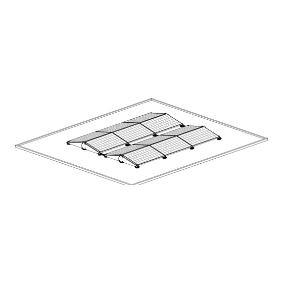
- Page 1 MANUAL FLATFIX FUSION MOUNTING SYSTEM FOR FLAT ROOFS FlatFix Fusion mounting system for flat roofs for solar panels in a dual landscape arrangement Rev. 30.11.17 © ESDEC BV 2017...
-
Page 2: Table Of Contents
The manufacturer renounces all responsibility for damage or injury caused by not carefully follow these installation instructions and the disregard of customary caution in the transport, assembling and use of the FlatFix Fusion installation system. As a result of constantly striving to improve, it may occur that the product is different from what is described in this manual. For this reason, the instructions given serve only as a guideline for installing the product mentioned in this manual. -
Page 3: Introduction
1. Introduction This manual describes the installation of the FlatFix Fusion mounting system for flat roofs (for solar panels in landscape arrangement). Read the instructions carefully so that you are totally familiar with the contents of the manual. Follow the instructions in the manual carefully. -
Page 4: General Installation Conditions
Avoid mounting during high winds and a slippery wet roof area. • The assembly of the FlatFix Fusion mounting system may only take place at temperatures between 5 º and 40 º C, • because of assembly joints of the synthetic material parts. - Page 5 The aluminium base profiles are attached to the base elements by means of a click-system. Use combination pliers to disassemble the base profile. Guarantee Guarantee according to the guarantee conditions and general terms and conditions of Esdec BV. These can be found on the website www.clickfit.nl. Liability...
-
Page 6: Product Description
Placing ballast You do not attach the FlatFix Fusion system to the roof; it stands loose on it. The roof supports must be glued to the roof at a roof slope of more than 3° (2° by PVC) . Please check the processing instructions of the kit and the roofing for their compatibility. -
Page 7: List Of Parts
For length see annex chpt. 8 16. Grounding clip Article nr: 100-7505 7. End clamp *optioneel Article nr: 100-41__ For type see annex chpt. 8 17. Grounding bracket Article nr:100-7503 *optioneel Rev. 30.11.17 MANUAL FLATFIX FUSION MOUNTING SYSTEM FOR FLAT ROOFS... -
Page 8: Assembling Preparation
Mastic gun optional Pincers Iron saw At roof slope > 2º / 3º Safety helmet Safety glasses Safety clothes Safety shoes Dust mask Ear protection Safety gloves Scaffold or stable safe ladder Rev. 30.11.17 MANUAL FLATFIX FUSION MOUNTING SYSTEM FOR FLAT ROOFS... -
Page 9: Determining Position And Measuring Solar Panels
Make sure that the place where the solar panels are to be placed on the roof is clean, dry and flat. The presence of gravel, sand, stones, algae, dust, etc. can lead to instability of the system and/or can cause damage to the roof. Rev. 30.11.17 MANUAL FLATFIX FUSION MOUNTING SYSTEM FOR FLAT ROOFS... -
Page 10: Installation
Use the two click connections from the middle for this (1A). 2. Attach the roof support to the lower base element by means of a click connection. 1A. When there is ballast CLICK! CLICK! CLICK! Rev. 30.11.17 MANUAL FLATFIX FUSION MOUNTING SYSTEM FOR FLAT ROOFS... -
Page 11: Grounding And Mounting Of Base Profile To Base Elements
3. Place the grounding spring into the slots in the low base units before clicking in the base profiles. 4. Slide the low base element (incl. roof support) on the other end of the base profile until it clicks. 5. One side of the FlatFix Fusion segment is ready. CLICK! CLICK! Rev. - Page 12 8. Slide the low base element (incl. roof support) on the other end of the base profile until it clicks. 9. The first FlatFix Fusion segment is ready. Repeat the abovementioned steps until you have enough Fusion segments to place the first two rows of solar panels.
-
Page 13: Positioning Of Flatfix Fusion Segments
7.3 Positioning of FlatFix Fusion segments You determine the position of the FlatFix Fusion segments based on the position of the solar panels on the roof. Divide the FlatFix Fusion segments proportionally in the line where the solar panels go. The FlatFix Fusion segments may be placed maximally 2 m apart from centre to centre (see calculator for distance). - Page 14 Place the second ballast holder between the FlatFix Fusion segments and in such a way that it overlaps the first ballast holder and that the elongated holes of the ballast holder are positioned over the upright notches of the high base element.
-
Page 15: Grounding And Mounting Of 1St Solar Panel
7.5 Grounding and mounting of 1st solar panel 1. Before placing the solar panels, it is optional to ground the FlatFix Fusion system per row. Place a grounding ring on both the Base element high and low. 2. Place the 1st solar panel between the upright notches of the low base element. -
Page 16: Mounting Of Other Solar Panels
Then screw in the two end clamps with the mounting screw in the mounting hole. Check that the solar panels are aligned properly before tightening the screw! CAUTION! The tightening torque of the screw connections is 4.5 Nm. Check that the mounting screws are not over- tightened in the base element. Rev. 30.11.17 MANUAL FLATFIX FUSION MOUNTING SYSTEM FOR FLAT ROOFS... -
Page 17: Mounting Of Cable Clips & Cables
4. Feed the end through one of the cable conductors of the high base element. 5. The plugs of the solar panel can be confirmed to the high base element in the cable conductor. Click! Ø25mm Rev. 30.11.17 MANUAL FLATFIX FUSION MOUNTING SYSTEM FOR FLAT ROOFS... -
Page 18: Grounding Of Multiple Rows (Option)
Place a grounding clip on each first solar panel in a row. When one makes use of the grounding rings in the FlatFix Fusion base elements the rest of the solar panels in the same row are automatically grounded. -
Page 19: Grounding Of Ballast Holders (Option)
The grounding cable used for the grounding of the rows can be used for grounding the ballast holder as well. Place a ground clip on every first and last ballast holder of a row to ground all rows individually. 0,24in Rev. 30.11.17 MANUAL FLATFIX FUSION MOUNTING SYSTEM FOR FLAT ROOFS... -
Page 20: Placement Of Ballast
If your roof is higher than 12 meters, we advise you to get in touch with your supplier; they can then determine the correct weight, depending on your situation. Rev. 30.11.17 MANUAL FLATFIX FUSION MOUNTING SYSTEM FOR FLAT ROOFS... -
Page 21: Mounting And Grounding Of Stabilizers
CAUTION! The tightening torque of the screw connections is 4.5 Nm Check that the bolts are not over-tightened in the base element. Repeat the previous step for the other intermediate stabilizers. Rev. 30.11.17 MANUAL FLATFIX FUSION MOUNTING SYSTEM FOR FLAT ROOFS... -
Page 22: Mounting Of 2Nd Row Of Solar Panels
Check that the mounting screws are not over-tightened in the base element. 7.12 Mounting of 2nd row of solar panels You can now mount the 2nd solar panels row. To do this, follow the assembling steps from Chapter 7.5 to 7.6. Rev. 30.11.17 MANUAL FLATFIX FUSION MOUNTING SYSTEM FOR FLAT ROOFS... -
Page 23: Mounting Of Wind Deflector Left/Right
Use the pre‐punched hole in the side wind deflector next to the bottom sun‐lock as a pilot. The side wind deflectors are now grounded and secured. And the first row of solar panels is ready! Rev. 30.11.17 MANUAL FLATFIX FUSION MOUNTING SYSTEM FOR FLAT ROOFS... -
Page 24: Several Rows Behind One Another
7.14 Several rows behind one another If you want to mount more rows of solar panels one behind the other, then you must first create FlatFix Fusion segments again (see section 7.1) and connect them to the base profile to the already mounted panel field. -
Page 25: Annex
46 mm 75 mm 46 mm 47 mm 75 mm 47 mm 48 mm 75 mm 48 mm 49 mm 75 mm 49 mm 50 mm 75 mm 50 mm Rev. 30.11.17 MANUAL FLATFIX FUSION MOUNTING SYSTEM FOR FLAT ROOFS... - Page 26 11. Available stabilizer (dual) Article nr Desciption Panel length 100-7070 FlatFix Fusion Stabilizer 1600 1611-1680 mm 100-7071 FlatFix Fusion Stabilizer 1200 1200-1306 mm 100-7072 FlatFix Fusion Stabilizer 1900 1900-1972 mm Rev. 30.11.17 MANUAL FLATFIX FUSION MOUNTING SYSTEM FOR FLAT ROOFS...
- Page 27 When determining the edge and angle zones of a building, it is necessary to adhere to the current regulations. When the edge and angle zones are indicated by Esdec, these are the minimum edge and angle zones. Placement of the solar panels in the edge and angle zones of a building is always at your own risk and is strongly discouraged.
Need help?
Do you have a question about the FlatFix Fusion and is the answer not in the manual?
Questions and answers