Siemens SIMATIC ET 200pro Quick Manual
Motor starters
Hide thumbs
Also See for SIMATIC ET 200pro:
- Operating instructions manual (545 pages) ,
- Original instructions manual (256 pages) ,
- Operating instruction (146 pages)
Table of Contents
Advertisement
Quick Links
SIMATIC
ET 200pro
Motor starters
Manual
Release 09/2007
GWA 4NEB 950 5661-02 DS 04
Preface, Table of contents
Description
Quick guide
Installation
Commissioning and
diagnostics
General technical
specifications
Rear wall bus modules
Special modules
Motor starters
Connecting
Device functions
Appendix
Order numbers
Dimensioned drawings
Applications
Data formats and data records
Glossary, Index
1
2
3
4
5
6
7
8
9
10
A
B
C
D
Advertisement
Chapters
Table of Contents

Related Manuals for Siemens SIMATIC ET 200pro


Summary of Contents for Siemens SIMATIC ET 200pro
- Page 1 Preface, Table of contents Description Quick guide Installation SIMATIC Commissioning and diagnostics ET 200pro Motor starters General technical specifications Rear wall bus modules Special modules Manual Motor starters Connecting Device functions Appendix Order numbers Dimensioned drawings Applications Data formats and data records Glossary, Index Release 09/2007 GWA 4NEB 950 5661-02 DS 04...
- Page 2 Brands All names identified by ® are registered trademarks of the Siemens AG. The remaining trademarks in this pub- lication may be trademarks whose use by third parties for their own purposes could violate the rights of the owner.
- Page 3 The manual describes all the functions of the ET 200pro motor starter. The manual does not deal with general ET 200pro functions. You will find these in the manual 'SIMATIC ET 200pro decentralized peripheral device'. Target group This manual is valid for ET 200pro motor starters. It is aimed at configuration engineers, commissioning engineers and maintenance personnel.
- Page 4 The manufacturer of the system or machine is responsible for ensuring correct overall functionability. Siemens AG, its sub- sidiaries and its affiliated companies (hereinafter designated “Siemens”) are not in a position to guarantee all features of a higher-order system or machine not designed by Siemens.
- Page 5 As well as this manual, you will need the manual for the DP master you are using. Note You will find a list of the contents of the SIMATIC ET 200pro manuals in Chapter 1.4 of this manual.We recommend that you begin by reading this section so as to find out which parts of which manuals are most relevant to you in helping you to do what you want to do.
- Page 6 Preface SIMATIC - ET 200pro motor starter GWA 4NEB 950 5661-02 DS 04...
-
Page 7: Table Of Contents
Table of contents Description ......Overview ....... . 1.1.1 Base components . - Page 8 4.5.3 Diagnosis disconnecting module 400 V (ASM-400 V) ..4.5.4 Diagnosis of motor starters DSe, sDSSte / sDSte, RSe, sRSSte / sRSte Process image ......4-11 4.6.1 Process image for special modules .
- Page 9 8.2.4 View of DSe and RSe motor starters, standard and high feature ..8.2.5 View of electronic starters sDSSte / sDSte and sRSSte / sRSte ..8.2.6 Connecting technology ......8.2.7 Parameters .
- Page 10 10.10.1Device parameters ......10-31 10.10.2Device parameters – settings..... . 10-32 10.10.3Signal.
-
Page 11: 1Device Parameters
Data formats and data records ....Data formats ......Identification number (ID no.), error codes . - Page 12 SIMATIC – ET 200pro motor starter GWA 4NEB 950 5661-02 DS 04...
- Page 13 Illustrations Figure 1-1: ET 200pro with motor starters ..... Figure 1-2: ET 200pro with motor starters and electronic modules ..Figure 1-3: ET 200pro with motor starters up to category 4 .
- Page 14 Figure 8-14: Load and motor torque as well as motor terminal voltage for operation at the soft starter ..... 8-37 Figure 8-15: Reduction depending on the installation height .
- Page 15 Tables Table 1-1: Base components ......Table 1-2: Special modules ....... Table 1-3: Motor starters .
- Page 16 Table 10-4: Thermal motor model – signals and actions ....10-9 Table 10-5: Thermal motor model – measured values and statistical data . . . 10-10 Table 10-6: Device parameters for current limits –...
- Page 17 Table D-15: Data record 96 – maximum pointers ....D-27 Table D-16: Data record 100 – read device identification ....D-29 Table D-17: Time stamp .
- Page 18 SIMATIC - ET 200pro motor starter GWA 4NEB 950 5661-02 DS 04...
-
Page 19: Description
Description Overview 1.1.1 Base components The following table shows the fundamental components required for a configu- ration with motor starters. Component Function Drawing Wide module ... is the mechanical holder in which the rear holder wall bus modules of the ET 200pro are lined (for motor up and on which the electronic modules and starter) -
Page 20: Special Modules
Component Function Drawing Rear wall bus ... accommodates a safety local mainte- module for nance isolating module. safety local maintenance isolating mod- Table 1-1: Base components (cont.) 1.1.2 Special modules Special modules are deployed if you • ... require the downstream motor starters to be switched off. •... -
Page 21: Motor Starters
1.1.3 Motor starters The following table shows the versions of the motor starters: Component Function Drawing Direct starter Direct starter, standard with electronic over- DSe; load protection standard ... switches a motor on or off..protects three-phase motors up to 5.5 kW in the event of overloading and short circuit- ing. -
Page 22: Accessories
Component Function Drawing Electronic Direct soft starter; high feature with elec- starter tronic overload protection sDSSte, ... switches a motor on or off. sDSte ... protects three-phase motors up to 5.5 kW high feature in the event of overloading and short circuit- ing. - Page 23 Component Function Drawing Crimping ... serve to secure the bushing and pin con- tools tacts at the ends of the cables..are available for 0.14 - 4 mm and 4 - 6 mm Dismounting ... are used to dismount the contacts from tools the plug cases.
-
Page 24: Configuration Options For Et 200Pro
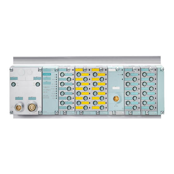
Configuration options for ET 200pro The motor starters and their properties can be combined as follows: • Standard motor starters and high feature motor starters can be combined as desired. ET 200pro with motor starters RSe, DSe, Interface maintenance sDSSte / sDSte; DSe, sRSSte / sRSte High feature... -
Page 25: Figure 1-1: Et 200Pro With Motor Starters
ET 200pro with motor starters up to category 4 Safety local maintenance Interface Isolating module DSe, RSe, sRSSte / sRSte; Isolating module module 400 V standard High feature Power infeed Power jumper Motor connection Wide module holder (for motor starter) Sealing cap Figure 1-3: ET 200pro with motor starters up to category 4 Parts list... -
Page 26: Limitation Of Connectable Modules / Maximum Configuration
Limitation of connectable modules / maximum configuration In your configuration (project planning) for an ET 200pro station, please observe the following rules: • The maximum number of modules is 16. These include: - Interface module - Electronic modules - Modules for reserve - Max. -
Page 27: Guide To The Et 200Pro Manuals
Guide to the ET 200pro manuals The components of the ET 200pro are described in two manuals. In the follow- ing examples, you will find possible configuration variants for the ET 200pro and the necessary manuals. You use the following components ... You will need information from ET 200pro consists of the following manuals:... -
Page 28: Table 1-2: Special Modules
Where do you find information? The following table is designed to help you quickly find the information you need. It tells you which manual you need to refer to and which section deals with the topic you are interested in. Manual section / appendix Decentralized Subject... -
Page 29: Quick Guide To Commissioning
Quick guide to commissioning Introduction and aim of the example Introduction On the basis of the following example, you will learn how to commission the ET 200pro with motor starters step by step. The DSe standard direct starter is controlled via an ON switch and on OFF switch connected to an 8 DI DC 24 V ST module. -
Page 30: Et 200Pro Components
ET 200pro components Required components The following table contains the components you require for this example: Number Order number Description 6ES7194-4GB00-0AA0 Wide module holder – Length 0.5 m 6ES7194-4GB10-0AA0 Wide module holder – Length 1 m (possible as an option) 6ES7154-2AA00-0AB0 Interface module IM 154-2 DP high feature with terminating module... -
Page 31: Requirements
Requirements The requirements for the example are: • You have set up an S7 station, consisting of a power supply assembly and a master with DPV1 capability (e.g. CPU 315-2 DP(1), no.: 6ES7315-2AG10-0AB0). For this example, a CPU 315-2 DP(1) has been used as DP master. It goes without saying that any other DPV1 master (standard IEC 61784-1:2002 Ed1 CP 3/1) can also be used. -
Page 32: Figure 2-2: Set Profibus Address 6
Order of assembly You will find an exact description for assembly for: • Assembling IM 154-. Assembling DP high feature and digital modules in the manual 'Decentralized peripheral system ET 200pro' • Assembling the rear wall bus module in Chapter 3.4 •... -
Page 33: Figure 2-3: Circuit For The Example
2.4.1 Circuit of the configuration example The following diagram shows the circuit of the main circuit and of the control current circuit for the example. Bus module Bus module Bus module IM 154-. Logic DSe-ST Logic Logic 1 2 3 1 2 3 1 2 3 1 2 3... -
Page 34: Cabling And Connecting
Cabling and connecting Perform the following steps: Caution Make sure that the entire configuration has adequate short circuit and overload protection. 2. Wire up the ET 200pro as shown in Figure 2-3. Only the external cables shown in bold are still to be connected. These are: –... -
Page 35: Configuring (Project Planning)
Configuring (project planning) 1. Start the SIMATIC Manager and set up a new project with a DP master (e.g. CPU315-2 DP) (see Figure 2-4). 2. Create the PROFIBUS subnet. 3. From the hardware catalog, insert the ET 200pro at the PROFIBUS. 4. -
Page 36: Integration Into The User Program
Setting the parameters for DP slave 8. To obtain diagnoses of the assemblies, please set the following parameters of the individual assemblies: - In the dialog field 'Properties DP slave for ET 200pro' Startup with target <> actual configuration: Enable Assembly change during operation: Enable - In the dialog field "Properties DP slave for DSe, Assembly / DP identifier 4 (in the configuration table) -
Page 37: Switching On
Switching on 1. Switch on the following voltage supplies at the ET 200pro. - Do not switch on 1L+ and 2L+ via the IM 154-. module supply voltage AC 400 V yet! 2. Observe the status LEDs on the DP master and ET 200pro. - CPU 315-2 DP: DC 5 V: lights up SF DP: Off... - Page 38 Checking the wiring Check for correct wiring of the ON switch and OFF switch. 6. Press the ON switch Observe the LEDs - 8 DI DC 24 V, DI green - DSe motor starter, STATE green. - DSe motor starter, DEVICE flashes yellow. - If SF is red at the DSe motor starter, the parameter for 'Response to resid- ual current detection' is set to "switch off".
-
Page 39: Diagnosis Possibilities
• Via the DP diagnosis modules for SIMATIC S7 "FB125" or "FC125". You can download the two components as well as a description in PDF format from the Internet at the following address: http://www4.ad.siemens.de/WW/view/de/387257 • Via 'HW Config' S7. See next Chapter 2.9.1... -
Page 40: Diagnosis Via 'Hw Config' In Step7
2.9.1 Diagnosis via ’HW Config’ in STEP7 1. On your PC or programming device, start the SIMATIC Manager and open the 'HW Config' window. 2. Open the "Online" station 3. Simulate the various errors and observe the signals in the status window 'DP slave diagnosis', for example: - Switch off voltages 1L+ and / or 2L+ - Switch off maintenance switch... -
Page 41: Help
Help Should you have any problems or questions, please contact: Technical Assistance: Telephone: +49 (0) 911-895-5900 (8°° - 17°° CET) Fax: +49 (0) 911-895-5907 E-mail: technical-assistance@siemens.com Internet: www.siemens.de/lowvoltage/technical-assistance Technical Support: Telephone: +49 (0) 180 50 50 222 SIMATIC – ET 200pro motor starter... - Page 42 SIMATIC - ET 200pro motor starter 2-14 GWA 4NEB 950 5661-02 DS 04...
-
Page 43: Installation
Installation Installation rules Installing the wide module holder For assembly of the wide module holder, please consult the manual 'Decentral- ized peripheral device ET 200pro'. On assembly, observe the following: – Maximum permitted length: 1 m – A maximum of 8 motor starter modules can be operated on one ET 200pro inter- face module Easy installation The decentralized peripheral system ET 200pro is designed for simple installa-... -
Page 44: Figure 3-1: Installation Position
Assembly rules for the installation of an ET 200pro with motor starters Observe the following rules for assembly (See also illustrations in Chapter 1.2 "Configuration options for ET 200pro"): • Installation in a single line on the wide module holder. •... -
Page 45: Installation Measurements And Clearances
Installation measurements and clearances Measurement module Installation Rear wall bus module for motor starters and special modules width Installation Without power connector: height • Special modules • Standard motor starter • High feature motor starter Installation On wide module holder with rear wall bus module for: depth •... -
Page 46: Derating
Derating 3.3.1 What is derating? Derating is the specific deployment of devices with power output restrictions even under difficult operating conditions. In the case of special modules and motor starters, these involve operation at high ambient temperatures (> 40°C). 3.3.2 Derating factors In the case of the ET 200pro special modules and motor starters, the following factors must be taken into account for deployment in difficult ambient condi-... -
Page 47: Figure 3-2: Diagrams For Derating
horizontal assembly vertical assembly ASM 400V ASM 400V F-RSM F-RSM DSe, RSe DSe, RSe ϑ ϑ [°C] [°C] sDSSte / sDSte sDSSte / sDSte sRSSte / sRSte sRSSte / sRSte Figure 3-2: Diagrams for derating SIMATIC – ET 200pro motor starter GWA 4NEB 950 5661-02 DS 04... -
Page 48: Assembling The Rear Wall Bus Module
Assembling the rear wall bus module Features Rear wall bus modules serve as the electrical connection of the special modules and motor starters with the head module. Requirements The space for the interface module IM 154-. is taken into account. Assembling the rear wall bus module for special modules and motor starter The following example shows the assembly of a rear wall bus module. -
Page 49: Assembling Special Modules And Motor Starters
Assembling special modules and motor starters Requirements All rear wall bus modules for electronic modules, special modules and motor starters have been assembled. Assembling the special modules and motor starters The special modules and motor starters are placed on the mounted rear wall bus modules and screwed onto the module holder with 3 Philips screws. -
Page 50: Installing The Terminating Module
The ET 200pro is only ready to operate when the terminating module has been connected. The terminating module is included in the delivery of the interface module IM 154-.. You will find more information on this in the manual SIMATIC ET 200pro decentralized peripheral system. Drawing Procedure/Description... -
Page 51: Connecting The Cables
Connecting the cables Drawing Procedure/Description Connect the cables and power jumpers according to your config- uration on the corresponding con- nections. Then lock the connected cables and power jumpers. Connect the M12 cables accord- ing to your configuration on the corresponding connections. -
Page 52: Fitting Cover Caps
Fitting cover caps In the case of special modules as well as motor starters, unused connections must be closed off with terminal covers to protect open contacts against dirt and to reliably seal the ET 200pro to IP65 standard. The terminal covers are to be ordered separately. Unused M12 connections must also be closed off with sealing caps. -
Page 53: Removing Motor Starters
Removing motor starters One motor starter can be removed from the rear wall bus module during opera- tion. The feeder must be without current, e.g. maintenance switch switched off. Remove the cable to the motor as well as the two power jumpers on the left and right from the motor starter to be replaced. - Page 54 Drawing Procedure/Description Unscrew the 3 Philips screws on the motor starter. Remove the motor starter towards the front. Table 3-7:Removing motor starters (cont.) Note We recommend that the maintenance and service personnel be informed in detail regarding correct handling of the motor starter prior to handover of the system in order to be able to use the advantages of the ET 200pro from the out- set in the event of a replacement.
-
Page 55: Commissioning And Diagnostics
Commissioning and diagnostics Commissioning The motor starter modules are parameterized using the PROFIBUS DP standard procedure on start-up. A change to parameters as well as use of a control device can also be made during operation alternatively via bus and the DP V1 mechanism or via the optical device interface locally. - Page 56 After overload or short-circuit tripping • Following a short circuit, the internal fusible links and switching elements of motor starters can be defective. • Following an overload tripping – fusible links OK – you have the possibility to reset the overload tripping. Reset possibilities are: –...
-
Page 57: Project Planning
Project planning Project planning involves configuring and parameterizing the ET 200pro. You will find more information on this in the manual 'SIMATIC ET 200pro decen- tralized peripheral system'. The following table shows which STEP 7 version is required for operation of the modules. - Page 58 Updating the software To update your software via the Internet, please proceed as follows: 1. Open the STEP 7 software 'HW Config' 2. Open the menu item 'Extras' > 'Install HW updates' 3. In the screen that now appears, enable the option 'Download from the Inter- net' (make sure that there is an active connection to the Internet) 4.
-
Page 59: Configuring With A Gsd File
GSD file in the configuration software. Requirements You require a GSD file that you can download from the Internet at: http://support.automation.siemens.com/WW/view/de/21221197 • Interface module IM 154-1 DP: GSD file SIEM8118.GSG • Interface module IM 154-2 DP high feature: GSD file SIEM8119.GSG Configuring the ET 200pro at the PROFIBUS DP with STEP 7 1. -
Page 60: Diagnostics
(DI 0.3=1) are transferred in cycles. For detailed diagnosis evaluation and sample programs with STEP 5 and STEP 7 , consult the manual 'SIMATIC ET 200pro decentralized peripheral system'. For the user program, the S7 components FB125 and FC125 are available for diagnosis evaluation. -
Page 61: Table 4-3: Motor Starter Fault Types
Motor starter fault types Motor starters Fault type Meaning / cause Remedy Direct starter 00100: • Thermal motor model • Let motor cool down DSe, sDSSte / Overload overload • Check current consumption of sDSte (F4) the motor • Check set current limits 00111: •... -
Page 62: Led Displays
LED displays 4.5.1 Diagnosis maintenance isolating module (RSM) Group error Status/Cause/Remedy Operating status Device error (device diagnosis detected by interface module IM 154-.) 1) Status of the LED in this form only with activated group diagnosis 4.5.2 Diagnosis of safety local maintenance isolating module (F-RSM) Group error POWER L2 active... -
Page 63: Diagnosis Disconnecting Module 400 V (Asm-400 V)
4.5.3 Diagnosis disconnecting module 400 V (ASM-400 V) Group error Status/Cause/Remedy Operating status General fault (is set by the IM 154-.) / device error 1) Status of the LED in this form only with activated group diagnosis 4.5.4 Diagnosis of motor starters DSe, sDSSte / sDSte, RSe, sRSSte / sRSte Group error DEVICE Device sta-... - Page 64 LEDs Status/Cause/Remedy STATE Device flickers Self-test running flashes Device not initialized green (send device for repair) Device error (device sets general fault) Current flow present without switch-on com- mand (e.g. contactor fused) Electronics defective, self-test error No connection to the ESSA (ESSA defective) System fault / warning (device sets general fault) Yellow...
-
Page 65: Process Image For Special Modules
Process image 4.6.1 Process image for special modules Input signals Maintenance iso- Safety local mainte- Disconnecting mod- lating module nance isolating mod- ule 400 V DI 0.0 Module status: Module status: Module status: DI 0.1 Status of the safety Status of the safety busbar busbar Not used... -
Page 66: Process Image For Motor Starter
4.6.2 Process image for motor starter Input signals DI 0.0 Ready (Automatic) DI 1.0 Motor current I pres Starter not ready via Bit 0 host / PLC Starter ready for operation via host DI 0.1 Motor on DI 1.1 Motor current I pres Bit 1 On (clockwise/counterclock-... -
Page 67: Self-Test
Output signals DO 0.0 Motor CLOCKWISE DO 1.0 Not used Motor off Motor on DO 0.1 Motor COUNTER-CLOCK- DO 1.1 Not used WISE (for RSe) Motor off Motor on DO 0.2 Activation for DO 1.2 Not used brake No drive - brake active - Motor braked Drive... -
Page 68: Table 4-5: Logbook Entries
Logbook entries The following logbook entries are stored in the starter and can be read via 'Motor Starter ES', version 2006 or higher: • Device error DS 72 • Trips DS 73 • Events DS 75 The 3 logbooks are organized as ring buffers, each with 126 bytes. The entries are made together with the current hours of operation of the device in each case. - Page 69 Statistical data (DS 95) The following data is stored in the data record 95 of the starter: • Hours of operation – device • Hours of operation – motor • Hours of operation motor current = 18 ... 49.9% of I e max •...
-
Page 70: Table 4-6: System Diagnosis
System diagnosis (see also manual 'ET 200pro decentralized peripheral device') In ET 200pro devices with diagnostic capability, device-specific diagnoses are recorded via allocated PROFIBUS error numbers. The error numbers in each case are sent to the ET 200pro interface module IM 154-. The system diagnosis indicates whether there is a channel error. -
Page 71: Software 'Motor Starter Es
Device diagnosis In the input process image of the starters, and general faults (DI 0.2) and gen- eral warning signals that are present (DI 0.3) are transferred in cycles. If required, more detailed information on the defect type is accessible by calling up the diagnosis (V1 system diagnosis). -
Page 72: Order Numbers
Deployment The diagnosis and commissioning tool 'Motor Starter ES' is suitable for the fol- lowing motor starters: • Standard DSe, RSe • High feature DSe, sDSSte / sDSte, RSe, sRSSte / sRSte The connection between the PC or programming device and the motor starter is set up via an infrared RS232 PC cable. -
Page 73: General Technical Data
General technical data Shipping and storage conditions Shipping and storage conditions With regard to shipping and storage conditions, the motor starters meet the requirements complying with IEC 61131, Part 2. The following data applies to assemblies that are shipped and/or stored in the original packaging. Type of condition Permissible range Free fall... -
Page 74: Mechanical And Climatic Environmental Conditions
Mechanical and climatic environmental conditions Installation position Horizontal assembly on a vertical wall with a maximum angle of inclination of 22.5°. Mechanical ambient conditions Vibrations tested complying with IEC 60068, Part 2-6 • Oscillation type: frequency sweeps with a rate of change of 1 octave a minute - 5 Hz <... -
Page 75: Rear Wall Bus Modules
Rear wall bus modules Rear wall bus modules for special modules and motor starter Features • The rear wall bus module 3RK1922-2BA00 is suitable for accommodating a special module or motor starter • The rear wall bus module 3RK1922-2BA01 is suitable for accommodating a safety local maintenance isolating module •... -
Page 76: Table 6-1: Technical Data For Rear Wall Bus Module
6.1.1 Technical specifications Dimensions and weight Installation measurements W x H x D 110 x 130 x 22.5 (mm) Weight (g) approx. 210 Shock protection Type of protection complying with IEC IP65 60529 (after assembly in line with regulations) Measurement data of the conductor bars Supply voltage 1L+, 2L+ 24 V DC Current load capacity I... -
Page 77: Special Modules
Special modules Special modules are fitted for the power infeed, short-circuit protection and trip- ping for a number of downstream motor starters. With the special modules 'safety local maintenance isolating module' and 'dis- connecting module 400 V', the safety level of category 4 can be achieved with the corresponding circuit design. -
Page 78: Maintenance Isolating Module (Rsm)
Maintenance isolating module (RSM) 7.2.1 Features The maintenance isolating module is configured for the following individual functions: • Disconnecting the downstream starters from the mains voltage • Closing lockout via padlock at the rotary element • Short-circuit protection for the downstream consumer units with 25 A circuit breaker 7.2.2 View of maintenance isolating module... -
Page 79: Figure 7-2: Circuit Diagram Of Maintenance Isolating Module
7.2.3 Sketched circuit diagram Module status DI 0.0 Logic 1 2 3 Figure 7-2: Circuit diagram of maintenance isolating module 7.2.4 Assignment of the main power connections Number Connection X1 Connection X2 Connection X3 HAN Q4/2 (pin) HAN Q4/2 (socket) HAN Q4/2 (socket) Phase L1 Phase L1... -
Page 80: Safety Local Maintenance Isolating Module (F-Rsm)
Safety local maintenance isolating module (F-RSM) 7.3.1 Features Safety guideline The module is to be tested on commissioning and thereafter every 12 months. For the test, proceed as follows: Operate the EMERGENCY OFF switch Check whether the output OUT has been switched off Check whether the AC 400 V has been switched off Enable the EMERGENCY OFF switch again With a monitored start, check whether the output OUT and the 400 V are still... -
Page 81: Description
7.3.2 Description The safety local maintenance isolating module contains a 3TK2841 assembly and is equipped with M12 connections for the connection of external safety components. Either 1-channel or 2-channel EMERGENCY OFF / EMERGENCY STOP circuits or guard door circuits can be connected at connection 1 (IN 1 / IN 2). Both mechanical switches and electronic sensors can be connected. -
Page 82: View Of Safety Local Maintenance Isolating Module
7.3.3 View of safety local maintenance isolating module Diameter £ 8 mm Rotary element for circuit breaker with closing lockout via padlock FAULT LED general fault POWER 1-channel Label 2-channel Connection 2 (START) Connection 1 (IN1, IN2) with status display Slide switch Connection 3 (OUT) for function selection... -
Page 83: Figure 7-5: Circuit Diagram For Safety Local Maintenance Isolating Module
7.3.4 Sketched circuit diagram DI 0.0 Module status Status safety output DI 0.2 IN 1 EMERGENCY OFF or safety door 1st channel IN 2 EMERGENCY OFF or safety door 2nd channel IN 3 monitored START F0 supply of the F0 busbar 3TK2841 Configuration 1-channel / 2-channel Configuration monitored START / autostart... -
Page 84: Figure 7-7: Assignment Of The Auxiliary Current Circuits At The Safety Local Maintenance Isolating Module
Assignment of the auxiliary current circuits Mechanical EMERGENCY OFF START 1-channel Channel 1 Pin 1: output (2L+) Mechanical EMERGENCY OFF Pin 2: not connected 2-channel Pin 3: not connected Pin 4: start input Channel 1 Pin 5: not connected Electronic sensor 1-channel Pin 1: not connected Pin 2: not connected... -
Page 85: Response To Fault
Caution Configuration changes must be made with the 2L+ supply switched off. Changes made with the 2L+ supply applied lead to an error message and the outputs being switched off. To reset the error message and adopt the changed configuration, the 2L+ supply must be switch off and on again. Electronic sensors must be operated in the operating mode "1-channel opera- tion". -
Page 86: Disconnecting Module 400 V (Asm-400V)
Disconnecting module 400 V (ASM-400V) 7.4.1 Features Safety guideline The module is to be tested on commissioning and thereafter every 12 months. For the test, proceed as follows: - Switch off the safety module that supplies the F0 busbar. - Check whether the 400 V has been switched off - Switch on the safety module that supplies the F0 busbar. -
Page 87: View Of Disconnecting Module
7.4.3 View of disconnecting module 400 V LED general fault Label Plug connector to Plug connector to looping though the Infeed of the Main power (X2) main power (X1) Locking bracket Figure 7-9: View of disconnecting module 400 V 7.4.4 Sketched circuit diagram DI 0.0 Module status... -
Page 88: Figure 7-11: Assignment Of The Connectors On The Disconnecting Module 400 V
7.4.5 Assignment of the main power connections Number Connection X1 Connection X2 HAN Q4/2 (pin) HAN Q4/2 (socket) Phase L1 Phase L1 Phase L2 Phase L2 Phase L3 Phase L3 — — — — — — Figure 7-11: Assignment of the connectors on the disconnecting module 400 V 7.4.6 Response to fault If an internal fault occurs, the outputs remain without current and the fault is... -
Page 89: Power Bus
Power bus Load group All the motor starters supplied via a single power bus infeed are referred to as a load group. Within a group of motor starters, a renewed power bus infeed can be required, e.g. so that the rated operating current (summation current) of the internal power bus is not exceeded. -
Page 90: Parameters And Technical Data
Parameters and technical data 7.6.1 Parameters There is a description of the parameters in Chapter The following table indicates the parameters that can be set for the special modules. Action, Parameters Factory setting Applicability value range Group diagnosis • Disable Disable Module •... - Page 91 Mainte- Safety local Disconnect- Special module nance isolat- mainte- ing module nance isolat- module 400 ing module Utilization category — — To carry and trip the rated operating cur- rent on opera- tion of the safety device (EMER- GENCY STOP) Maximum duration of use no restriction 10 years...
- Page 92 Mainte- Safety local Disconnect- Special module nance isolat- mainte- ing module nance isolat- module 400 ing module Switching times at 0.85 ... 1.1 x U • Closing time — — 425 ... 525 ms • Opening delay 40 ... 60 ms Insulation resistance Rated impulse strength U 6 kV...
-
Page 93: Motor Starters
Motor starters Overview The integrated electronic overload protection for motor starter enables coverage of the current range up to 12 A with only two device versions. The ET 200pro motor starters can be parameterized and enable access to comprehensive diagnosis and statistical data. -
Page 94: Electronic Starters
8.1.2 Electronic starters The electronic starters ET 200pro are offered as directly (sDSSte / sDSte) and reversing starters (sRSSte / sRSte) in the high feature version with the following equipment. • 4 digital inputs • with soft start-up and soft run-down function •... -
Page 95: Properties Of The Motor Starters
Properties of the motor starters 8.2.1 ET 200pro motor starter DSe ST, RSe ST • DSe ST are motor starters for a single direction of rotation that can be can be used in the decentralized peripheral device ET 200pro • RSe ST are motor starters for two directions of rotation with mechanical lock- ing of clockwise and counterclockwise operation that can be used in the decentralized peripheral device ET 200pro •... -
Page 96: Electronic Starters Et 200Pro Sdsste / Sdste, Srsste / Srste
8.2.3 Electronic starters ET 200pro sDSSte / sDSte, sRSSte / sRSte • Have the same basic properties as DSe HF and RSe HF motor starters • Have an additional soft start-up and soft run-down function • With the soft start function deactivated, the motor starter can be used as an electronic directly and reversing starter •... -
Page 97: Figure 8-2: View Of Electronic Starters Sdsste / Sdste And Srsste / Srste
8.2.5 View of electronic starters sDSSte / sDSte and sRSSte / sRSte LED general fault Label with LED STATE optical LED DEVICE Interface Input IN 1 to IN 4 with status display Plug connector to looping though the Plug connector to main power (X3) Infeed of the main power (X1) -
Page 98: Figure 8-3: Assignment Of The Main Power Connections At The Motor Starter
8.2.6 Connecting technology Assignment of the main power connections Number Connection X1 Connection X2 Connection X3 HAN Q4/2 (pin) HAN Q8/0 (socket) HAN Q4/2 (socket) Phase L1 L1 out Phase L1 Phase L2 Not used Phase L2 Phase L3 L3 out Phase L3 Not used Brake L1... -
Page 99: Figure 8-4: Assignment Of M12 Plug Connector At The Motor Starter
Auxiliary current circuits On an ET 200pro motor starter, there are the following auxiliary current circuits: • 1L+: Electronics voltage supply via the rear wall bus module to supply elec- tronics and connected sensors at the inputs IN 1 to IN 4. •... -
Page 100: Figure 8-5: Circuit Diagram - Dse Direct Starter, Standard And High Feature
Circuit diagram for direct starters DSe (ST and HF) and el. starters sDSSte / sDSte DI 0.0 Ready via host / PLC Motor on / current flow DI 0.1 Group error DI 0.2 General warning DI 0.3 Input 1 DI 0.4 Input 2 DI 0.5 Logic... -
Page 101: Figure 8-6: Circuit Diagram - Rse Reversing Starter, Standard And High Feature
Circuit diagram for rev. starters RSe (ST and HF) and el. rev. starters sRSSte / sRSte DI 0.0 Ready via host / PLC Motor on / current flow DI 0.1 Group error DI 0.2 General warning DI 0.3 Input 1 DI 0.4 Input 2 DI 0.5... -
Page 102: Table 8-2: Parameters For Motor Starters Dse, Rse (Standard And High Feature); Sdsste / Sdste, Srsste / Srste
8.2.7 Parameters There is a description of the parameters in Chapter The following table shows which actions or value ranges can be set for each parameter on the DSe / sDSSte / sDSte and RSe / sRSSte /sRSte motor starters. Action, Applica- Parameters... - Page 103 Action, Applica- Parameters Factory setting value range bility Blocking current limit value 150% ... 1000% I 800% Module with soft starter only 800% Blocking time limit value 1 s ... 5 s Module Type of start-up • direct Voltage ramp and •...
- Page 104 Group diagnosis: This parameter enables diagnosis messaging (error types are listed in Chapter 4.4). Note The parameter "Disable group diagnosis" also suppresses the SF LED displays of malfunctions set by the head. The changed fault recording and display via SF LED remains active.
-
Page 105: Table 8-3: Technical Data Of The Motor Starters
8.2.8 Technical specifications Special module DSe ST DSe HF sDSSte / RSe ST RSe HF sDSte sRSSte / sRSte Dimensions and weight Installation measurements (mm):width height depth Weight (g) DSe / sDSSte / sDSte: 1385 1395 1700 RSe / sRSSte / sRSte: 1655 1665 1875... - Page 106 Permitted switching frequency max. 80/h Table 8-6 Table 8-7 Insulation resistance Rated impulse strength U 6 kV 4 kV Rated insulation voltage U 400 V Protective separation between main and control current 400 V, in accordance with EN 60947-1 circuits Appendix N Circuits with rated voltage U against other circuits or...
- Page 107 Technical data – brake control (only with order end number ...AA3) Rated operating voltage AC 400 V ≤ 0.5 A Continuous current ≤ 5 A Switch-on current at t < 120 ms ≤ 0.5 A Switch-off current AC 15, at 400 V Permitted brake (example) with one-way same direction on ≤...
-
Page 108: Figure 8-7: Electrical Service Life Of Contactor
Technical data – inputs (only for high feature motor starters) Input characteristics complying with Type 1 IEC 61131 Input voltage • rated value 24 V DC • for signal "0" -3 ... +5 V • for signal "1" 11 ... 30 V Input current •... -
Page 109: Figure 8-8: Typical Current And Torque Characteristics Of A 3-Phase Induction Motor
Electronic starters sDSSte / sDSte / sRSSte / sRSte The electrical properties of the direct soft starter DSSe are comparable with those of the 2-phase SIRIUS soft starter. The following variants of type 1 are available: • 2 A without bridge •... -
Page 110: Figure 8-9: Current And Torque Characteristics With Star-Delta Start
Reducing the start-up current There are various possibilities to reduce the start-up current: • using star-delta starters • using frequency converters • using soft starters Star-delta starters After a certain switching time, the motor windings are switched from the star circuit into the delta circuit. -
Page 111: Figure 8-10: Phase Control Of The Mains Voltage By Means Of Semiconductor Elements On The Soft Starter Sdsste / Srsste
Soft starter sDSSte / sRSSte (soft start function activated) In the case of a soft starter, the motor voltage is raised by phase control within a start-up time from an adjustable start voltage to the rated motor voltage. As the motor current is proportionally to the motor voltage, the start current is reduced by the factor of the set start voltage. -
Page 112: Figure 8-11: Current And Torque Characteristics When A Soft Starter Is Used
Example: Starting voltage 50% of U => start torque 25% of the start torque with direct start. Advantages: • Low space requirement in the control cabinet • No circuits (e.g. filters) necessary to comply with interference suppression regulations • Low assembly overhead •... - Page 113 8.3.2 Application and use Areas of application and selection criteria The electronic starters ET 200pro sDSSte / sDSte and sRSSte / sRSte represent an alternative to star-delta starters, frequency converters and mechanical switchgears (comparison and advantages, see Chapter 8.3.1). The most important advantages with the activated soft start function are soft start-up and run-down, uninterrupted switchover without peak loads that place stress on the network, and the small dimensions.
- Page 114 8.3.3 Features The electronic starters ET 200pro sDSSte / sDSte and sRSSte / sRSte • Are suitable for switching and protecting 3-phase current consumer units up to 5.5 kW at AC 400 V • Are available in 2 setting ranges with 0.15 - 2 A and 1.5 - 12 A •...
-
Page 115: Figure 8-12: Time Ramp / Time Diagram, Sdsste / Sdste, Srsste / Srste
Soft run-down function The drive coming to an abrupt standstill on switching off the motor is prevented by the integrated soft run-down function. Warning In the case of a switch-off function with motor brake, the soft run-down with its delay time works against the braked motor. Direct start function Direct start for three-phase induction motors without torque reduction with the aim of high switching frequency. - Page 116 Stop voltage The parameter "stop voltage" sets the voltage value whereby run-down type "voltage ramp" aborts the run-down, i.e. is switched off. Current limitation value The parameter "current limitation value" limits the start-up current to the param- eterized value. Duty cycle The relative duty cycle in % is the ratio between the load duration and cycle time for consumer units that are frequently switched off and on.
-
Page 117: Table 8-6: Switching Frequencies With Activated Soft Start Function
3RK1304-5KS70-..(0.15 A to 2 A) Class 10a Device installation vertical horizontal Rated current I 40°C 50°C 55°C 40°C 50°C 55°C Ambient temperature Type of protection Duty cycle = 30%, Start /1 s Duty cycle = 70%, Start /1 s Duty cycle = 30%, Start /2 s Duty cycle = 70%, Start... - Page 118 CLASS 20 Device installation vertical horizontal Rated current I 40°C 50°C 55°C 40°C 50°C 55°C Ambient temperature Type of protection Duty cycle = 30%, Start /1 s Duty cycle = 70%, Start /1 s Duty cycle = 30%, Start /2 s Duty cycle = 70%, Start /2 s 3RK1304-5LS70-..
- Page 119 CLASS 15 Device installation vertical horizontal Rated current I 4.5 A 40°C 50°C 55°C 40°C 50°C 55°C Ambient temperature Type of protection Duty cycle = 30%, Start /3 s Duty cycle = 70%, Start /3 s Duty cycle = 30%, Start /6 s Duty cycle = 70%, Start /6 s...
- Page 120 CLASS 10 Device installation vertical horizontal Rated current I 5.8 A 4.5 A 40°C 50°C 55°C 40°C 50°C 55°C Ambient temperature Type of protection Duty cycle = 30%, Start /2 s Duty cycle = 70%, Start /2 s Duty cycle = 30%, Start /4 s Duty cycle = 70%, Start /4 s...
- Page 121 3RK1304-5LS70-..(1.5 A to 12 A) Class 10a Device installation vertical horizontal Rated current I 40°C 50°C 55°C 40°C 50°C 55°C Ambient temperature Type of protection Duty cycle = 30%, Start /1 s Duty cycle = 70%, Start /1 s Duty cycle = 30%, Start /2 s Duty cycle = 70%, Start...
- Page 122 CLASS 20 Device installation vertical horizontal Rated current I 40°C 50°C 55°C 40°C 50°C 55°C Ambient temperature Type of protection Duty cycle = 30%, Start /4 s Duty cycle = 70%, Start /4 s Duty cycle = 30%, Start /8 s Duty cycle = 70%, Start /8 s 3RK1304-5LS70-..
- Page 123 CLASS 15 Device installation vertical horizontal Rated current I 12 A 12 A 12 A 12 A 12 A 11 A Ambient temperature 40°C 50°C 55°C 40°C 50°C 55°C Type of protection Duty cycle = 30%, Start /3 s Duty cycle = 70%, Start /3 s Duty cycle = 30%, Start /6 s...
-
Page 124: Table 8-7: Switching Frequencies With Deactivated Soft Start Function (Direct Start)
3RK1304-5KS70-..(0.15 A to 2 A) Class 10a Device installation vertical horizontal Rated current I 40°C 50°C 55°C 40°C 50°C 55°C Ambient temperature Type of protection Duty cycle = 30% (8xI 300 2000 300 2000 300 2000 300 2000 300 2000 300 2000 0.2 s Duty cycle = 70% (8xI 180 1000 180 1000 180 1000 180 1000 180 1000 180 1000... - Page 125 CLASS 10 Device installation vertical horizontal Rated current I 4.5 A 40°C 50°C 55°C 40°C 50°C 55°C Ambient temperature Type of protection Duty cycle = 30% (8xI 0.5 s Duty cycle = 70% (8xI 0.5 s Duty cycle = 30% (8xI Duty cycle = 70% (8xI 3RK1304-5LS70-..
- Page 126 3RK1304-5LS70-..(1.5 A to 12 A) Class 10a Device installation vertical horizontal Rated current I 40°C 50°C 55°C 40°C 50°C 55°C Ambient temperature Type of protection Duty cycle = 30% (8xI 0.35 s Duty cycle = 70% (8xI 0.35 s Duty cycle = 30% (8xI 0.7 s Duty cycle = 70% (8xI...
- Page 127 CLASS 10 Device installation vertical horizontal Rated current I 12 A 12 A 12 A 12 A 12 A 11 A Ambient temperature 40°C 50°C 55°C 40°C 50°C 55°C Type of protection Duty cycle = 30%, Start /2 s Duty cycle = 70%, Start /2 s Duty cycle = 30%, Start /4 s...
- Page 128 8.3.4 Notes on configuration (project planning) So that a motor can reach its rated speed in the first place, the motor torque greater than the torque required by the load all through powering up, as other- wise a stable operating point sets in even before the rated speed of the motor is reached ("the motor gets stuck").
-
Page 129: Figure 8-14: Load And Motor Torque As Well As Motor Terminal Voltage For Operation At The Soft Starter
motor start-up with motor load ET 200pro soft starter = acceleration torque of the motor start-up with SIRIUS soft starter Figure 8-14: Load and motor torque as well as motor terminal voltage for operation at the soft starter Selection criteria Note In the case of the ET 200pro soft starters sDSSte / sDSte and sRSSte / sRSte, the corresponding soft starter must be selected according to the motor rated... -
Page 130: Figure 8-15: Reduction Depending On The Installation Height
Startup time To achieve optimal operating conditions for the soft starter sDSSte / sRSSte, the set start-up time should be approx. 1 s longer than the resulting motor powering up time. Longer start-up times increase the thermal load on the devices and the motor unnecessarily and lead to a reduction in the permitted switching fre- quency. - Page 131 Connecting Warning Dangerous electrical voltage! Can lead to electrical shocks and burns. Before starting work, disconnect the system from the power supply. Danger Ensure correct and carefully wiring! Otherwise, ET 200pro components can be destroyed! There is danger to life! Shock protection The plug connectors HAN Q4/2 used for power infeed and HAN Q8/0 for consumer unit connection have adequate protection against acci-...
-
Page 132: Table 9-1: Rules For Wiring
Connecting Rules for wiring Warning Dangerous electrical voltage! Can lead to electrical shocks and burns. Before starting work, disconnect the system from the power supply. 9.1.1 Selecting the power cables The wire cross-section of the power cables must be adapted to the relevant ambient conditions. -
Page 133: Figure 9-1: Example: Power Infeed
Connecting Cutting power cables to length 9.2.1 To cut power cables to length, you require: • For assembly of the sockets and pins on the individual wires, a crimping tool (see Chapter A.2). As well as the following accessories: • For infeed to special modules (assignment of X1, see Chapter 9.2.2), for infeed to motor starters (assignment of X1, see... -
Page 134: Figure 9-2: Example: Power Infeed With Turned Socket Insert
Connecting Energy infeed DC 24V Connector set 7-pin (socket) angled cable routing with turned socket insert Figure 9-2: Example: power infeed with turned socket insert DC 24V DC 24V Other Station alternatively Connector set Connector set 7- 7-pin (pins) pin (socket) angled angled Power relaying... -
Page 135: Figure 9-4: Example: Motor Connection Cable
Connecting DC 24V Connector set 9-pin (pin) angled cable routing Motor connection cable Figure 9-4: Example: motor connection cable SIMATIC – ET 200pro motor starter GWA 4NEB 950 5661-02 DS 04... -
Page 136: Figure 9-5: Plug Connector For Special Modules Rsm And F-Rsm
Connecting 9.2.2 Plug connector for special modules RSM and F-RSM The power plug connectors X1 for infeed and/or X2 for loop-through to the spe- cial modules RSM and F-RSM consist of the following components: X1 infeed HAN Q4 / 2-socket Plug case Cable gland with seal insert... -
Page 137: Figure 9-6: Plug Connector For Motor Starter
Connecting 9.2.3 Plug connector for motor starter The power plug connectors X1 for infeed and/or X2 for consumer unit connec- tion to the motor starters consist of the following components: X1 infeed HAN Q4 / 2-socket Coding Socket Assignment X1 Plug case Phase L1 Phase L2... -
Page 138: Table 9-2: Mounting And Wiring The Power Plug Connector
Connecting 9.2.4 Mounting and wiring the power plug connector Mount and wire the power plug connector according to the following specifications: Step Procedure Route the cable through the cable gland, the matching enclosed seal insert and the plug case. The seal insert is available in the following grades: Permitted outer diameter of the cable Seal insert 7.0 to 10.5 mm... -
Page 139: Table 9-3: Power Jumper
Connecting Power jumper The power jumper serves to loop through the main power from a special mod- ule or motor starter to the next motor starter. The following table shows the assignment of the contacts: Socket Assignment Phase L1 Phase L2 Phase L3 Not used PE (yellow / green) - Page 140 Connecting SIMATIC - ET 200pro motor starter 9-10 GWA 4NEB 950 5661-02 DS 04...
-
Page 141: Figure 10-1: Device Functional Principle
Device functions 10.1 Introduction Device function This section describes the device functions. All the device functions have inputs (e.g. the device parameters) and outputs (e.g. signals). The following diagram illustrates the device functional principle: Inputs Outputs Device parameters Measured values Device function Commands Signals... - Page 142 10.2 Basic parameters Definition Basic parameters are "central" parameters required by several device functions. The number of device functions and the output class depend on the device ver- sion and cannot be parameterized. 10.2.1 Device parameters Rated operating current You use this parameter to specify the rated operating current that the feeder (switching devices and motor) can carry continuously.
-
Page 143: Table 10-1: Present Motor Current
Present motor current The maximum current in the motor starter is returned via the process image for evaluations. The current is measured in all 3 phases and the highest value is determined. The returned 6-bit value indicates the motor current ratio I pres rated rated... -
Page 144: Table 10-2: Basic Parameters - Settings
Protection against voltage failure (can only be parameterized for high feature motor starters) You use this parameter to retain the last overload signal • Overload • No overload 10.2.2 Parameter settings The following table shows the settings of the basic parameters: Device parameters Default Adjustment range... - Page 145 10.3 Thermal motor model Description The approximate winding temperature of the motor is calculated electronically using the measured motor currents and the device parameters 'rated operating current' and 'tripping class'. This indicates, depending on the temperature, whether the motor is overloaded or functioning in the normal operating range. 10.3.1 Device parameters Response to overload –...
-
Page 146: Figure 10-2: Tripping Classes
Tripping class (can only be parameterized for high feature motor starters) The ’tripping class’ (CLASS) indicates the maximum time to disengagement in which a safety device must trip with 7.2 times the current setting from the cold state (motor protection complying with IEC60947). The tripping characteristics show the time to disengagement depending on the tripping current. - Page 147 Recovery time (can only be parameterized for high feature motor starters) The ’recovery time’ is the time specified for cooling, after which the system can be reset if overload tripping occurs. During the recovery time, pending trip reset signals (DO 0.3) have no effect. The motor starters are set to the following times: •...
-
Page 148: Figure 10-3: Cooling Down Characteristics With And Without Idle Time
Idle time (can only be parameterized for high feature motor starters) The 'idle time' is a specified time for the cooling down characteristics after shut- down by control functions at operating temperature, i.e. not due to overload. When this time has elapsed, the thermal memory of the motor starter is deleted and a cold start is possible. -
Page 149: Table 10-3: Device Parameters For Thermal Motor Model - Settings
10.3.2 Thermal motor model – settings The following table shows the settings of the device parameters: Device parameters Default Adjustment range Response to overload – thermal motor Trip without restart Trip without restart / model Trip with restart / Warning Tripping class 5, 10, 15, 20 (only for DSe HF,... -
Page 150: Table 10-5: Thermal Motor Model - Measured Values And Statistical Data
Measured values and statistical data Measured values Description Remaining cooling time — Phase current I Present phase current, phase 1 L1 pres Phase current I Present phase current, phase 2 L2 pres Phase current I Present phase current, phase 3 L3 pres Motor heating Current motor heating in %... - Page 151 10.4 Current limits Description The motor current and current limits can be used to draw conclusions regarding various system states: System state Current value Protection by: System becomes sluggish (e.g. due to Current is greater Current limits damaged bearings) System runs more smoothly (e.g. less than normal because there is no material left to pro- cess).
- Page 152 Upper / lower current limit (can only be parameterized for high feature motor starters) You can enter an upper and / or a lower current limit. Example: • 'Mixing mass too viscous', i.e. upper current limit is exceeded. • 'Idling because drive belt torn', i.e. the lower current limit is undershot. Caution The current limits are not activated until the class time elapses (for example, after 10 seconds for class 10) to permit the time for starting to be bridged.
- Page 153 Principle of blocking protection when powering up The following diagram illustrates the block protection principle when powering up, that is, the relationship between the blocking current and blocking time: Case 1: Motor continues to run Blocking Blocking Blocking current Removed within blocking time Motor continues to run Motor current...
-
Page 154: Table 10-6: Device Parameters For Current Limits - Settings
10.4.2 Device parameters for current limits – settings The following table shows the settings of the device parameters: Device parameters Default Adjustment range Response to current limit violation Warning Warning / Tripping Lower current limit 18.75% 18.75% to 100% Increment: 3.125 % Upper current limit 112.5% 50% to 150%... - Page 155 10.4.4 Temperature sensor Task Temperature sensors are located directly in the stator winding of the motor. They are used for direct temperature monitoring of the motor windings. This indicates whether the motor is overloaded or functioning in the normal operating range. Caution Electronic starters sDSSte / sDSte and sRSSte / sRSte can evaluate one tem- perature sensor circuit!
-
Page 156: Table 10-8: Device Parameters For Temperature Sensor - Settings
Response to overload - temperature sensor You use this parameter to set how the motor starter is to respond in the case of 'Overload – Temperature sensor' and if the temperature sensor monitoring is activated: • Trip without restart • Trip with restart •... -
Page 157: Table 10-9: Temperature Sensor - Signals And Actions
Signals and actions The device function "Temperature sensor" delivers the following signals and actions: Signal Action Temperature sensor overload Warning or tripping Temperature sensor wire break Warning or tripping Temperature sensor short circuit Warning or tripping Overload tripping Tripping (overload, wire break or short cir- cuit), depending on parameterization Table 10-9: Temperature sensor –... - Page 158 10.5 Asymmetry Description Three-phase induction motors respond to slight asymmetries in the mains volt- age with a higher asymmetric current consumption. As a result, the tempera- ture in the stator and rotor winding increases. Caution When the motor is switched on, the asymmetry evaluation is suppressed for approximately 500 milliseconds.
-
Page 159: Table 10-10: Device Parameters For Asymmetry - Settings
10.5.2 Device parameters for asymmetry – settings The following table shows the settings of the device parameters: Device parameters Default Adjustment range Response to asymmetry Tripping Warning / Tripping Asymmetry limit value 30% to 60% Increment: 10% Table 10-10: Device parameters for asymmetry – settings 10.5.3 Signals, actions and measured values The device function 'Asymmetry' delivers the following signals and actions:... - Page 160 10.7 Inputs (can only be parameterized for high feature motor starters) Description With the device function 'Inputs', the motor starter can run various actions that you can parameterize. The signals at both digital inputs are evalu- ated for this purpose. You can connect the inputs directly to sensors (PNP) in 2- wire and 3-wire circuits.
- Page 161 Input n – level You use this device parameter to define the input logic. Setting range: break contact / make contact Caution With 'Input n - action': 'Emergency start', 'Motor CLOCKWISE', 'Motor COUNTER-CLOCKWISE' and 'Trip reset', 'Input n - level' can only be parameter- ized as a make contact! Caution If 'Input n - level' is parameterized from break contact to make contact and the...
-
Page 162: Table 10-13: Description Of 'Input N - Action
Input n – action – level – Signal Operati Description mode No action NO / n.la / la — Trip NO / n.la / – • Leads to the motor and brake switching off. without • Acknowledgment after removal of the cause of restart the tripping (initial state) is required. - Page 163 Input n – action – level – Signal Operati Description mode Motor CLOCK- S / – n.la / la Manual • For these operations, the motor starter must be WISE opera- in the operating mode 'Manual operation local'. tion • The device braking parameters are evaluated. local •...
-
Page 164: Table 10-14: Device Parameters For Inputs - Settings
10.7.2 Device parameters for inputs – settings The following table shows the settings of the device parameters: Device parameters Default Adjustment range Input signal extension 0 milliseconds 0 milliseconds to 200 milliseconds Increment: 10 ms. Input signal delay 10 milliseconds 10 milliseconds to 80 milliseconds Increment: 10 ms. -
Page 165: Table 10-15: Inputs - Signals And Actions
10.7.3 Signals and actions The device function 'Inputs' delivers the following signals and actions: Signal Action Input 1 — Input 2 — Input 3 — Input 4 — Input 'Tripping' Tripping (must be acknowledged with trip reset) Input tripping – end position clockwise Tripping (must be acknowledged with countercom- Input tripping –... -
Page 166: Figure 10-5: Principle Of Soft Start-Up / Soft Run-Down
10.8 Soft starter control function Description Soft starters work according to the principle of phase angle control. You can specify soft start-up and soft run-down with a variable voltage ramp. The following diagram shows the principle: Soft start-up Soft run-down Mains Mains voltage... -
Page 167: Table 10-16: Device Parameters For Soft Starter Control Function - Settings
Device parameters for soft starter control function – description Startup time The motor terminal voltage is increased on a linear basis from the start voltage during the parameterizable start-up time to the full mains voltage. Setting range: 0 to 30 seconds Run-down time The motor terminal voltage is increased on a linear basis from the mains voltage during the parameterizable run-down time to the stop voltage. - Page 168 10.9 Field bus interface 10.9.1 Device parameters Response to CPU / master STOP This device parameter configures how the motor starter responds to a CPU / master STOP: • Retain the last value • Switch substitute value Caution This device parameter is only relevant in the operating mode 'Automatic'. Group diagnosis You use this parameter to enable or disable diagnosis via PROFIBUS DP (error type).
-
Page 169: Table 10-17: Device Parameters For Response To Bus Failure - Settings
Substitute value In the event of a bus failure, a corresponding substitute process image of the outputs controls the motor starter. Example: Substitute value Motor CLOCKWISE Reserved Motor COUNTER-CLOCK- Reserved WISE Brake Reserved Trip reset Reserved Emergency start Reserved Self-test Reserved Reserved Disable quick stop... -
Page 170: Figure 10-6: Example Of A Circuit For Mechanical Braking
10.10 Mechanical braking Description A mechanical disk or spring-loaded brake attached to the motor brakes the motor. The brake is controlled via the brake output. Example of a circuit The following diagram shows an example of a circuit for mechanical braking: L1 L2 L3 Assignment Current... - Page 171 10.10.1 Device parameters Brake release delay on starting Caution Only effective with simultaneous SWITCH-ON command for brake and motor. Caution: • Positive times: Delayed switch-on of the brake output with respect to the motor. • Negative times: Delayed switch-on of the motor with respect to the brake output.
-
Page 172: Table 10-18: Device Parameters For Mechanical Braking - Settings
10.10.2 Device parameters – settings The following table shows the settings of the device parameters: Device parameters Default Adjustment range Brake release delay on starting -2.5 s to 2.5 s Increment: 0.01 s Brake hold time on stopping 0 s to 25 s Increment: 0.01 s Table 10-18: Device parameters for mechanical braking –... -
Page 173: Table 10-20: Self-Test - Test Steps
10.11 Self-test Description There are 2 types of self-test: • Cyclical self-test during operation Run cyclically during operation • Self-test on command Activated by the user via bit DO 0.5 'Self-test' in the process image of the outputs. Test steps The self-test consists of 3 test steps. -
Page 174: Table 10-21: Self-Test - Signals
Error in self-test In the event of errors, the LED 'DEVICE' lights up red. The error can only be acknowledged by switching on again. If the error is still present, the self-test will not be performed correctly during startup. The motor starter must be replaced! 10.11.1 Signals This device function delivers the following signals:... -
Page 175: Table 10-22: Emergency Start - Commands
10.12 Emergency start Description 'Emergency start' enables a recovery despite an internal switch-off command. Emergency start is possible if • 'SWITCH-ON command' for the motor is present. The motor is switched on even if the cause of the trip is still present. •... -
Page 176: Table 10-24: Factory Setting - Signals
10.13 Factory setting Description The 'Factory setting' function enables you to restore the settings defined when the motor starter was delivered. In this way, you can reset the motor starter if it has been incorrectly parameterized. Restoring the factory setting You can restore the factory setting using the 'Factory setting' command. - Page 177 10.14 Maintenance Description Maintenance functions are required to prevent failures in devices and systems due to wear. This increases the availability of the system. Optimized use is achieved when the motor starter indicates its own imminent failure or that of the motor in good time in stages.
-
Page 178: Table 10-25: Device Parameters For Control Function Reversing Starter - Settings
10.15 Control function reversing starter Description This control function enables the RSe motor starter to control the motor direc- tion. The internal logic prevents both contactors from pulling in simultaneously. Time-delayed switching from one motor direction to the other is enabled by means of the lock-out time. -
Page 179: Table 10-27: Electronic / Mechanical Switching Technology - Signals And Actions
10.16 Electronic / mechanical switching technology Electronic switching technology The motor starter controls the motor with power semiconductors in 2 phases with thyristors Mechanical switching technology The motor starter controls the motor in 3 phases with contactors. 10.16.1 Signals and actions These device functions deliver the following signals: Signal Action... -
Page 180: Figure 10-7: Local Device Interface
10.17 Local device interface Description The local optical device interface can be used to connect the motor starter to a PC (accessory cable required) or a hand-held terminal. The local optical device interface is located on the front, beneath the label. Local optical device interface Figure 10-7: Local device interface Caution... -
Page 181: Figure 10-8: Data Channels
10.18 Communication Description The communication is a higher level device function that consists of a number of sub-functions: • Operating mode monitoring • Rear-wall bus connectivity • Commands • Plausibility check of data • Output of signals 10.18.1 Operating mode monitoring Data channels ET 200pro motor starters have 3 different data channels: Local optical device interface... -
Page 182: Table 10-28: Master Control Of The Operating Modes
Operating modes The following operating modes are distinguished with rising priority: • Operating mode 'Automatic' (lowest priority) Control of the motor starter is only with PLC via field bus. • Operating mode 'Manual bus' Control of the motor starter is only possible with a control device (e.g. PC) via field bus. -
Page 183: Table 10-29: Operating Modes
Connection monitoring The connection monitoring is active in the operating modes 'Manual bus' and 'Manual operation local'. At least one write data record must be sent within 5 seconds, otherwise the motor starter switches off and the signal 'Manual oper- ation connection abort' is output. -
Page 184: Table 10-30: Commands And Their Meanings
10.18.2 Commands Commands and their meanings Using the commands, you can instruct the motor starter to carry out certain actions. Using the Switch ES configuration software, for example, you can send the fol- lowing commands to the motor starter: Command Meaning Trip reset •... -
Page 185: Table 10-31: Communication - Signals
10.18.3 Plausibility check of data Description The motor starer checks that all the incoming parameters are valid and plausi- ble. In the event of incorrect parameters • During startup (after Power ON), the signals 'General fault' and 'Incorrect parameter value' are displayed. Motor and brake output remain switched off. - Page 186 Signals Meaning Parameter assignment Parameterization active Yes / No Incorrect parameter value Parameter not correct Parameter change illegal in the ON state Attempted parameter change not permit- ted when motor is running. Incorrect parameter number Specifies the first non-accepted parameter (parameter ID no.) Parameter block CPU / Master active Motor starter ignores parameters from the...
- Page 187 10.19 Logbook Description The logbook contains a chronological list of trips, device faults, and events, which are assigned a time stamp and can be used to create a log. This log is then saved internally. This provides the possibility to evaluate the causes later. Logbooks Three types of logbook are available, which can be read as data records: •...
- Page 188 Logbook – trips The 'Logbook – trips' records all general faults. The ID numbers of the actual causes of faults are entered (e.g. 'Switching element overload'). Observe the following points: • The logbook - trips is deleted using the 'Delete logbook – trips' command. Logbook –...
-
Page 189: Et 200Pro Direct Starter, Standard Without Inputs
Order numbers Motor starters A.1.1 ET 200pro direct starter, standard without inputs Adjustment range Order number Direct starter Direct starter with brake control (DSe) (DSe) 0.9 kW 0.15 - 2 A 3RK1304-5KS40-4AA0 3RK1304-5KS40-4AA3 5.5 kW 1.5 - 12 A 3RK1304-5LS40-4AA0 3RK1304-5LS40-4AA3 A.1.2 ET 200pro direct starter, high feature with 4 inputs... -
Page 190: Et 200Pro Reversing Starter, Standard Without Inputs
A.1.3 ET 200pro reversing starter, standard without inputs Adjustment range Order number Reversing starter Reversing starter with brake control (RSe) (RSe) 0.9 kW 0.15 - 2 A 3RK1304-5KS40-5AA0 3RK1304-5KS40-5AA3 5.5 kW 1.5 - 12 A 3RK1304-5LS40-5AA0 3RK1304-5LS40-5AA3 A.1.4 ET 200pro reversing starter, high feature with 4 inputs Adjustment range Order number Reversing starter... -
Page 191: Et 200Pro Electronic Reversing Starter; High Feature With 4 Inputs
A.1.6 ET 200pro electronic reversing starter; high feature with 4 inputs Adjustment range Order number Electronic reversing Electronic reversing starter starter with brake control (sRSSte / sRSte) (sRSSte / sRSte) 0.9 kW 0.15 - 2 A 3RK1304-5KS70-3AA0 3RK1304-5KS70-3AA3 5.5 kW 1.5 - 12 A 3RK1304-5LS70-3AA0 3RK1304-5LS70-3AA3... -
Page 192: Components For Et 200Pro Motor Starter
Components for ET 200pro motor starter Description Model Order number mech., 25 A 3RK1304-0HS00-6AA0 Maintenance isolating module with 3TK2841 functionality 3RK1304-0HS00-7AA0 Safety local maintenance isolating module Safety disconnecting module 3RK1304-0HS00-8AA0 Disconnecting module 400 V with 2 contactors 0.5 m length (ready to fit) 6ES7194-4GB00-0AA0 Wide module holder 1 m length (ready to fit) -
Page 193: B Dimensioned Drawings
Dimensioned drawings Maintenance isolating module SIMATIC – ET 200pro motor starter GWA 4NEB 950 5661-02 DS 04... -
Page 194: Safety Local Maintenance Isolating Module
Safety local maintenance isolating module SIMATIC - ET 200pro motor starter GWA 4NEB 950 5661-02 DS 04... -
Page 195: Disconnecting Module
Disconnecting module 400 V SIMATIC – ET 200pro motor starter GWA 4NEB 950 5661-02 DS 04... -
Page 196: Dse St, Rse St Motor Starters
DSe ST, RSe ST motor starters SIMATIC - ET 200pro motor starter GWA 4NEB 950 5661-02 DS 04... -
Page 197: Dse Hf, Rse Hf Motor Starters
DSe HF, RSe HF motor starters SIMATIC – ET 200pro motor starter GWA 4NEB 950 5661-02 DS 04... -
Page 198: Electronic Starters Sdsste/Sdste, Srsste/Srste
Electronic starters sDSSte/sDSte, sRSSte/sRSte SIMATIC - ET 200pro motor starter GWA 4NEB 950 5661-02 DS 04... -
Page 199: C Applications
Applications Safety guideline The following applications are illustrated merely as examples of circuits. No liability is accepted for the functionability, certifiability or compatibility of the examples. Use at your own risk. Caution The operation of 3-phase motors in a star-shaped circuit can lead to high EMC interference (especially if <... -
Page 200: Standard Applications
Applications Standard applications C.1.1 With maintenance isolating module and ECOFAST connection The following example shows a configuration with infeed via a maintenance iso- lating module to the motor starters. A motor with ECOFAST starter is connected at connection X2 of the maintenance isolating module. Figure C-1: Configuration with maintenance isolating module and ECOFAST connection SIMATIC - ET 200pro motor starter GWA 4NEB 950 5661-02 DS 04... - Page 201 Applications Figure C-1: (cont.) Configuration with maintenance isolating module and ECOFAST connection SIMATIC – ET 200pro motor starter GWA 4NEB 950 5661-02 DS 04...
-
Page 202: Without Maintenance Isolating Module
Applications C.1.2 Without maintenance isolating module The following example shows a configuration with direct infeed to the motor starters. There is short-circuit protection of the configuration outside the ET 200pro. Figure C-2: Configuration without maintenance isolating module SIMATIC - ET 200pro motor starter GWA 4NEB 950 5661-02 DS 04... - Page 203 Applications Figure C-2: (cont.) Configuration without maintenance isolating module SIMATIC – ET 200pro motor starter GWA 4NEB 950 5661-02 DS 04...
-
Page 204: For Hot Swapping
Applications C.1.3 For hot swapping The following example shows a configuration with direct infeed to each motor starter. There is short-circuit protection of the configuration outside the ET 200pro. The direct infeed into each motor starter means that individual motor starters can be replaced during operation. - Page 205 Applications Figure C-3: (cont.) Configuration for hot swapping SIMATIC – ET 200pro motor starter GWA 4NEB 950 5661-02 DS 04...
-
Page 206: Safety Applications
Applications SAFETY applications Safety guideline In the case of configurations for safety applications of category 2 to 4, as a gen- eral principle a safety local maintenance isolating module is to be used in con- junction with a disconnecting module 400 V. An automatic restart in conjunction with EMERGENCY STOP is not permitted. - Page 207 Applications Figure C-4: (cont.) Configuration with EMERGENCY STOP , 1-channel with monitored START SIMATIC – ET 200pro motor starter GWA 4NEB 950 5661-02 DS 04...
-
Page 208: Emergency Stop , 2-Channel With Monitored Start
Applications C.2.2 EMERGENCY STOP , 2-channel with monitored START The following example shows a configuration with EMERGENCY STOP with monitored START for category 4. Caution With the safety local maintenance isolating module for your use case, please ensure that the two coding switches are in the right positions. Figure C-5: Configuration with EMERGENCY STOP , 2-channel with monitored START SIMATIC - ET 200pro motor starter C-10... - Page 209 Applications Figure C-5: (cont.) Configuration with EMERGENCY STOP , 2-channel with monitored START SIMATIC – ET 200pro motor starter C-11 GWA 4NEB 950 5661-02 DS 04...
-
Page 210: Safety Door Monitoring, 1-Channel With Automatic Restart
Applications C.2.3 Safety door monitoring, 1-channel with automatic restart The following example shows a configuration with safety door monitoring with automatic restart of category 2. Optionally, a tumbler for safety doors can be connected at output OUT 1. Caution With the safety local maintenance isolating module for your use case, please ensure that the two coding switches are in the right positions. - Page 211 Applications Figure C-6: (cont.) Configuration for safety door monitoring, 1-channel, and automatic restart SIMATIC – ET 200pro motor starter C-13 GWA 4NEB 950 5661-02 DS 04...
- Page 212 Applications SIMATIC - ET 200pro motor starter C-14 GWA 4NEB 950 5661-02 DS 04...
-
Page 213: Figure D-1: Current Formats
Data formats and data records Data formats Features The motor starter determines a large amount of operation, diagnosis and statis- tical data. Control data is transferred to the motor starter. Control data Data that is transferred to the motor starter, e.g. switching command Motor COUNTER-CLOCKWISE, trip reset etc. - Page 214 Data formats and data records Statistical data device service life • Hours of operation The motor starter records 2 hours of operation values: – The hours of operation of the motor, specifying how long the motor was switched on. – The hours of operation of the device (motor starter), specifying how long the voltage supply DC 24 V-NS of the motor starter was switched on.
- Page 215 Data formats and data records Identification number (ID no.), error codes D.2.1 Identification number (ID no.) The identification number (ID no.) provides unique identification of all the infor- mation available in the motor starter (parameters, control commands, diagnosis, commands, etc.). It is located in the data record tables in the left-hand column. D.2.2 Error codes in the case of negative data record acknowledgment Description...
-
Page 216: Table D-1: Error Codes
Data formats and data records Error code The following error code are generated by the motor starter: Error codes, bytes Error message Cause High 00 H 00 H No error — Communication interface 80 H A0 H Negative acknowledgment for •... -
Page 217: Figure D-2: Byte Arrangements In The Format 'Big Endian
Data formats and data records Data records Writing / reading data records with STEP7 You can access the data records of the motor starter from the user program. • Writing data records: S7-DPV1 master: By starting SFB 53 ’WR_REC’ or SFC 58 S7-Master: By starting SFC 58 •... -
Page 218: Table D-2: Data Record 68 - Read / Write Process Image Of The Outputs
Data formats and data records D.3.1 Data record 68 – read / write process image of the outputs Note Bear in mind that data record 68 is overwritten in the Automatic operating mode by the cyclical process image! Byte Meaning Header label Coordination 0x20 write via C1 channel (PLC) -
Page 219: Table D-3: Data Record 69 - Read Process Image Of The Inputs
Data formats and data records D.3.2 Data record 69 – read process image of the inputs Byte Meaning Process image of the inputs Process data DI 0.0 to DI O.7, table below Process data DI 1.0 to DI 1.7, table below Reserved = 0 Reserved = 0 ID no. -
Page 220: Table D-4: Data Record 72 - Logbook - Device Errors
Data formats and data records D.3.3 Data record 72 – logbook – device errors Byte Meaning Value range Increment Note 0…3 Hours of operation – 1…4294967295 device Oldest entry 4…5 Object number 0…32767 signed 16 1 120… Hours of operation – 1…4294967295 Last, device... - Page 221 Data formats and data records ID no. Device errors – signals Note Stack overflow — Stack underflow — External interrupt — Undefined operation code — Protection fault — Illegal Word Operand Access — Illegal Instruction Access — Address / data disrupted (illegal external bus —...
- Page 222 Data formats and data records ID no. Device errors – signals Note EEPROM: memory defective — EEPROM: CRC error 'fixed value parameters' — EEPROM: CRC error 'Device parameters' — EEPROM: CRC error 'Bus parameters' — EEPROM: contains invalid data! — EEPROM: value for 'parameterization lock —...
- Page 223 Data formats and data records ID no. Device errors – signals Note — — — — — — EEPROM power unit: CRC error — — — Switching element defective — 1414 Switching element short-circuited — 1466 Contact 1 failed — 1467 Contact 2 failed —...
-
Page 224: Table D-6: Data Record 73 - Read Logbook - Trips
Data formats and data records D.3.4 Data record 73 – read logbook – trips Byte Meaning Value range Increment Note 0…3 Hours of operation – 1…4294967295 device Oldest entry 4…5 ID number device error 0…32767 signed 16 1 120… Hours of operation – 1…4294967295 Last, device... -
Page 225: Table D-8: Data Record 75 - Read Logbook - Events
Data formats and data records ID no. Trips – signals Note Sensor supply overload — Process image error — Incorrect parameter value — ID no. of the incorrect parameter — Memory module defective Exact cause additionally in the logbook – device errors Memory module programming defective —... -
Page 226: Table D-9: Read Signals In The Logbook - Events
Data formats and data records The following signals can be entered: ID no. Events – signals Note Warnings Temperature sensor overload ± (incoming / outgoing event) Temperature sensor wire break ± (incoming / outgoing event) Temperature sensor short circuit ± (incoming / outgoing event) Thermal motor model overload ±... -
Page 227: Table D-10: Data Record 92 - Read Device Diagnosis
Data formats and data records D.3.6 Data record 81 – read base setting DS 131 The structure and content of data record 81 correspond to those of data record 131. Data record 81 delivers the default values for all the parameters of the DS 131. - Page 228 Data formats and data records ID no. Byte Signaling bit F no. Meaning / Acknowledgment Start-up active In the case of soft starters — Signaling bit is continuously updated Coasting down active — Brake output active Brake output is switched on by user —...
- Page 229 Data formats and data records ID no. Byte Signaling bit F no. Meaning / Acknowledgment Generator motor run Motor feeds power back to motor starter. — Signaling bit is continuously updated Input control Motor CLOCKWISE, Motor COUNTER-CLOCK- — WISE control commands via the input actions Signaling bit is continuously updated Asymmetry detected Asymmetry has occurred...
- Page 230 Data formats and data records ID no. Byte Signaling bit F no. Meaning / Acknowledgment Earth fault detected Earth-fault current present — Signaling bit is continuously updated Earth fault tripping Earth-fault current present and tripping Signaling bit is deleted when cause of the trip has been removed and acknowledged with trip reset Quick stop active...
- Page 231 Data formats and data records ID no. Byte Signaling bit F no. Meaning / Acknowledgment 1444 Manual operation local – Manual operating mode – local active, — input controls + input controls active 1445 Manual local operation – con- Not supported —...
- Page 232 Data formats and data records ID no. Byte Signaling bit F no. Meaning / Acknowledgment 6…7 FW update 00 : rejected / state after reset — 01 : active 10 : successful 11 : defective (F9) Signaling bit is always deleted if acknowledged with 'Trip reset'.
-
Page 233: Table D-11: Structure Of The Command Data Record
Data formats and data records D.3.8 Data record 93 – write command Structure of the command data record Byte Meaning Note Command data record Header label Coordination 0x20 write via C1 channel (PLC) 0x30 write via C2 channel (PC) 0x40 write via device interface (PC) 1…3 Reserved Command... - Page 234 Data formats and data records ID no. Coding Command Meaning Parameter block CPU / Parameterization possible by means of parameter- Master OFF izing master Delete memory module Not supported Logbook – delete trips Deletes logbook with recorded error causes Logbook – delete Deletes logbook with recorded warning messages events and certain actions...
-
Page 235: Table D-13: Data Record 94 - Read Measured Values
Data formats and data records D.3.9 Data record 94 – read measured values ID no. Byte Meaning Value range / Increme Note [coding] Measured values 4…5 Remaining cooling time of the 0…1800 s 0.1 s motor 0…6 Motor heating 0…200% / [0…100] Asymmetry [0]: No asymm. - Page 236 Data formats and data records ID no. Byte Meaning Value range / Increme Note [coding] 44...45 Reserved = 0 46...47 Time tripping reserve of the 0...6 500 s 0.1 s FFFF thermal motor model time infinite 48...51 Reserved = 0 52...53 Reserved = 0 Reserved = 0 56...59 Reserved = 0...
-
Page 237: Table D-14: Data Record 95 - Statistical Data
Data formats and data records D.3.10 Data record 95 – statistical data ID no. Byte Meaning Value range / Increme Note [coding] Statistics Motor current I 0…796.9% 3.125% 8-bit current format max(%) Hours of operation resolu- 0 = 1 minute —... - Page 238 Data formats and data records ID no. Byte Meaning Value range / Increme Note [coding] 52...53 Reserved = 0 54...55 Reserved = 0 56...59 Number of stops with 0…4 294 967 295 mechanical braking 60...63 Reserved = 0 64...67 Reserved = 0 68...71 Reserved = 0 72...75 Reserved = 0 76...79 Reserved = 0...
- Page 239 Data formats and data records D.3.11 Data record 96 – maximum pointers ID no. Byte Meaning Value range / Increment Note [coding] Maximum pointers 14…15 Number of motor overload 0… 65 535 — trippings 12…13 Max. tripping current I 0…1000% 3.125% 9-bit current for- A max(%)
- Page 240 Data formats and data records ID no. Byte Meaning Value range / Increment Note [coding] 64...67 Hours of operation – motor 0…4 294 967 295 1 s / 1 min. Resolution is sig- current naled by infobit = 18...49.9 % x I "hours of opera- e max tion resolution"...
- Page 241 0x30 write via C2 channel (PC) 0x40 write via device interface (PC) Reserved1 Reserved2 Reserved3 Device identification (TF) 4…11 Time stamp 12…31 Siemens AG Manufacturer 32…55 — MLFB number 0x01 Device family: load feeder 0x01 Device subfamily: Motor starter 0x01 / 0x02 Device class: e.g.
- Page 242 Data formats and data records Object name id_date Object length 8 bytes Note Byte 0 to 59 999 milliseconds — 0 to 59 minutes 0 to 23 hours SU: 0: Normal time, 1: Summer time Weekday Day of the month 1 to 7;...
- Page 243 Data formats and data records Device parameters If the DP V1 functions are used, complete data records can be interchanged with the starters across the ET 200pro rear-wall bus. The telegram traffic between the interface module and the special modules or motor starters takes place in blocks of up to 16 bytes in length.
- Page 244 Data formats and data records ET 200 DS 131 Increme Factory Parameters Value range Relevant for Byte no. setting Byte 0…7 — Recovery time 60…1800 s 30 s 90 s DSe, RSe (HF); sDSSte/sDSte, sRSSte/sRSte 0…7 — Idle time 0…255 s DSe, RSe (HF);...
- Page 245 Data formats and data records ET 200 DS 131 Increme Factory Parameters Value range Relevant for Byte no. setting Byte Response to cur- warning — DSe, RSe (HF); rent limit violation tripping sDSSte/sDSte, sRSSte/sRSte Response to resid- warning — all starters ual current detection tripping 0…1...
- Page 246 Data formats and data records ET 200 DS 131 Increme Factory Parameters Value range Relevant for Byte no. setting Byte 0…3 0…3 Input 1 – action No action Tripping without 4…7 4…7 Input 2 – action restart 0…3 0…3 Input 3 – action Tripping with restart 4…7 4…7...
- Page 247 Data formats and data records ET 200 DS 131 Increme Factory Parameters Value range Relevant for Byte no. setting Byte 0…7 — Stop voltage 20% ... 90% sDSSte/sDSte, sRSSte/sRSte 0…7 3.125% — Current limitation 125% ... 600% 600% sDSSte/sDSte, value sRSSte/sRSte 0…3 —...
- Page 248 Data formats and data records D.4.1 Data record 134 – maintenance ID no. Byte Meaning Value range / [coding] Increment Factory setting — 0...3 NST2000 header In accordance with system specification — 4...7 Reserved — — — 8...11 Maintenance timer – warning 0...4 294 967 295 s 946 080 000 limit value_1...
- Page 249 Data formats and data records Identification data Definition Identification data is information stored in an assembly that supports the user • Checking the system configuration • Finding hardware changes in a system • Remedying errors / faults in a system The identification data can be used to uniquely identify assemblies online.
- Page 250 Data formats and data records Content Length Coding (bytes) (hex) F1 11 Corresponding data record number 00 E9 Length of the data record 00 40 Index 00 03 F1 11 Corresponding data record number 00 EA Length of the data record 00 40 Index 00 04...
- Page 251 I&M0 – data block 0 8 ... 9 00 01 Index (00 42 or 00 01) I&M 0 10 ... 11 00 2A MANUFACTURER_ID 42 = manufacturer designation SIEMENS 12 ... 31 (20 bytes) ORDER_ID Order number 32 ... 47 (16 bytes) SERIAL_NUMBER Serial number 48...49...
- Page 252 Data formats and data records SIMATIC - ET 200pro motor starter D-40 GWA 4NEB 950 5661-02 DS 04...
- Page 253 Glossary (PWR) supply voltage for electronics. (CON) supply voltage for contactor control. Direct starters → A direct starter is a motor starter for one direction of rotation that switches a motor on or off directly. It consists of a circuit breaker and a contactor. Load group A group of motor starters supplied by a single power bus infeed.
- Page 254 Motor starter, Standard Standard motor starters have the following properties: • Device designations: DSe, RSe • Optionally with externally supplied brake control • Usable up to 5.5 kW • Installation width:110 mm MS (motor starter) Motor starter is the generic term for direct and reversing starters. With motor starters the start-up and direction of rotation of a motor is deter- mined.
- Page 255 Index Numerics Commissioning Communication 10-41 1-channel operation Configuration Gl-1 Configuration options 2-channel operation Connecting Gl-1 Connecting technology 7-7, 8-6 Connecting the cables Accessories Connection cross-section, power Actions 10-9 infeed 8-13 Ambient conditions Connection monitoring 10-43 Applications Connection X1 7-3, 7-7, 7-12, 8-6 ASM-400V 1-2, 7-10 Connection X2...
- Page 256 Direct starter sDSte / sRSte (soft start function deactivated) 8-20 Identification data D-37 Direct starters 1-3, Gl-1 Idle time 8-10, 10-8 Disconnecting module 400 V 7-10 IM 154-. DP Disconnecting module 400 V IN 1 7-5, 8-7 Dismounting tool IN 2 DO, output signal 4-13 Input n –...
- Page 257 Manuals 10-4 Maximum configuration Protective circuit 8-1, C-1 Maximum current load capacity Maximum pointers 4-15, D-2 Q4/2 7-3, 7-7, 7-12, 8-6 Measured values 4-14, 10-10 Q8/0 Mechanical braking 10-30 Quick guide Mechanical service life, contactor 8-13 Minimum clearances Monitored start-up Ramp time 8-23 Monitoring...
-
Page 258: Table 8-4: Technical Data - Brake Control
Selecting the power cables Self-protection mechanism 10-1 Table of contents Self-test 10-33 Technical data – brake control 8-15 set current Technical data – inputs 8-16 Shipping conditions Technical specifications 5-1, 6-2, 7-14, 8- Shock protection Short-circuit protection 8-14 Temperature sensor 8-10, 10-15 Signal 10-32... - Page 259 Sender (please complete) Name Company / Office Siemens AG Address A&D CD MM 3 Phone 92220 Amberg Fax: + 49 9621 / 80-3337 Manual SIMATIC - ET 200pro motor starter Have you come across any errors in this manual? Please describe the errors on this form.
- Page 260 GWA 4NEB 950 5661-02 DS 04...
Need help?
Do you have a question about the SIMATIC ET 200pro and is the answer not in the manual?
Questions and answers