Siemens Simatic ET200pro Operating Instruction
Cpu 1516pro-2 pn
Hide thumbs
Also See for Simatic ET200pro:
- Operating instructions manual (545 pages) ,
- Quick manual (260 pages) ,
- Original instructions manual (256 pages)
Table of Contents
Advertisement
Quick Links
Advertisement
Table of Contents

Related Manuals for Siemens Simatic ET200pro


Summary of Contents for Siemens Simatic ET200pro
- Page 2 ___________________ CPU 1516pro-2 PN Preface (6ES7516-2PN00-0AB0) ___________________ Documentation guide ___________________ SIMATIC Product overview ___________________ Mounting and connecting ET 200pro CPU 1516pro-2 PN ___________________ (6ES7516-2PN00-0AB0) Configuring ___________________ Basics of program execution Operating Instructions ___________________ Protection ___________________ Commissioning ___________________ SIMATIC memory card ___________________ Maintenance ___________________...
- Page 3 Note the following: WARNING Siemens products may only be used for the applications described in the catalog and in the relevant technical documentation. If products and components from other manufacturers are used, these must be recommended or approved by Siemens. Proper transport, storage, installation, assembly, commissioning, operation and maintenance are required to ensure that the products operate safely and without any problems.
-
Page 4: Preface
Preface Purpose of the operating instructions This CPU 1516pro-2 PN operating instructions manual supplements the operating instructions of the ET 200pro decentralized I/O system. The information provided in this manual and the operating instructions of the ET 200pro enables you to commission the CPU 1516pro-2 PN. Basic knowledge required General knowledge in the field of automation engineering is required to understand this documentation. - Page 5 The supplier is also required to comply with certain measures for product monitoring. Siemens informs system operators in the form of personal notifications about product developments and properties which may be or become important issues in terms of operational safety.
- Page 6 In order to protect plants, systems, machines and networks against cyber threats, it is necessary to implement – and continuously maintain – a holistic, state-of-the-art industrial security concept. Siemens’ products and solutions only form one element of such a concept. Customer is responsible to prevent unauthorized access to its plants, systems, machines and networks.
- Page 7 Preface Industry Mall The Industry Mall is the catalog and order system of Siemens AG for automation and drive solutions on the basis of Totally Integrated Automation (TIA) and Totally Integrated Power (TIP). Catalogs for all the products in automation and drives are available on the Internet (https://mall.industry.siemens.com).
-
Page 8: Table Of Contents
Table of contents Preface ..............................4 Documentation guide ..........................11 Product overview ..........................15 Application ..........................15 How it works ........................... 17 Properties ..........................18 Operator control and display elements .................. 23 2.4.1 Front view of the module ......................23 Mode switch ........................... - Page 9 Table of contents Protection ............................. 59 Overview of the protection functions ..................59 Configuring access protection for the CPU................60 Using the user program to set additional access protection ........... 62 Know-how protection ......................63 Copy protection ........................66 Commissioning ............................. 68 Overview ..........................
- Page 10 Table of contents Interrupts, diagnostics, error messages and system events ..............113 11.1 Status and error display of the CPU ..................114 Technical specifications ........................118 12.1 Technical specifications ....................... 118 Dimension diagram ..........................129 Accessories/spare parts ........................130 Accessories/spare parts ....................... 130 Glossary ..............................
-
Page 11: Documentation Guide
Documentation guide The documentation for the SIMATIC S7-1500 automation system, the CPU 1516pro-2 PN based on SIMATIC S7-1500 and the SIMATIC ET 200MP distributed I/O system is arranged into three areas. This arrangement enables you to access the specific content you require. Basic information The System Manual and Getting Started describe in detail the configuration, installation, wiring and commissioning of the SIMATIC S7-1500 and ET 200MP systems. - Page 12 You must register once to use the full functionality of "mySupport". You can find "mySupport" on the Internet (https://support.industry.siemens.com/My/ww/en). "mySupport" - Documentation In the Documentation area in "mySupport" you can combine entire manuals or only parts of these to your own manual.
- Page 13 ● Manuals, characteristics, operating manuals, certificates ● Product master data You can find "mySupport" - CAx data on the Internet (http://support.industry.siemens.com/my/ww/en/CAxOnline). Application examples The application examples support you with various tools and examples for solving your automation tasks. Solutions are shown in interplay with multiple components in the system - separated from the focus on individual products.
- Page 14 You can find the SIMATIC Automation Tool on the Internet (https://support.industry.siemens.com/cs/ww/en/view/98161300). PRONETA With SIEMENS PRONETA (PROFINET network analysis), you analyze the PROFINET network during commissioning. PRONETA features two core functions: ● The topology overview independently scans PROFINET and all connected components.
-
Page 15: Product Overview
Product overview Application The CPU 1516pro-2 PN is a component of the ET 200pro distributed I/O system in degree of protection IP65, IP66 and IP67. The CPU provides you with maximum performance combined with excellent usability. It is suitable for a variety of demanding applications and communication tasks in automation engineering. - Page 16 Product overview 2.1 Application Safety Integrated The fail-safe CPU is intended for users who want to implement demanding standard and fail- safe applications both centrally and decentrally. The fail-safe CPU enables the processing of standard and safety programs on a single CPU. This allows fail-safe data to be evaluated in the standard user program.
-
Page 17: How It Works
Product overview 2.2 How it works How it works The CPU contains the operating system and executes the user program. The user program is located on the SIMATIC memory card and is processed in the work memory of the CPU. The PROFINET interfaces on the CPU allow simultaneous communication with PROFINET devices, PROFINET controllers, HMI devices, programming devices, other controllers and other systems. -
Page 18: Properties
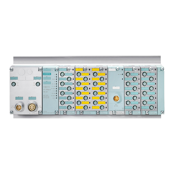
Product overview 2.3 Properties Properties Article number 6ES7516-2PN00-0AB0 (CPU 1516pro-2 PN) 6ES7194-4AP00-0AA0 (Connection module CM CPU 2PN M12 7/8") View of the module The figure below shows the CPU 1516pro-2 PN. Figure 2-1 CPU 1516pro-2 PN CPU 1516pro-2 PN (6ES7516-2PN00-0AB0) Operating Instructions, 09/2016, A5E35873416-AA... - Page 19 If you configure PROFINET IO communication on the 2nd PROFINET interface (X2) (operated as IO controller or IO device), additional system load occurs. You can find additional information in the Cycle and Response Times (https://support.industry.siemens.com/cs/de/de/view/59193558/en) Function Manual. Note IP subnets The IP subnets of both interfaces must be different.
- Page 20 Product overview 2.3 Properties ● Integrated Web server: A Web server is integrated in the CPU. The Web server enables monitoring and administering of the CPU by authorized users over a network. Evaluations, diagnostics, and modifications are thus possible over long distances. All you need is a web browser. With the Web server, you can read out the following data from the CPU and, in some cases, modify and write back the data to the CPU.
- Page 21 You can find a detailed description of the use of Motion Control and its configuration in the S7-1500 Motion Control (https://support.industry.siemens.com/cs/ww/en/view/59381279) function manual. You can also use the TIA Selection Tool (http://w3.siemens.com/mcms/topics/en/simatic/tia-selection-tool) or the SIZER (http://w3.siemens.com/mcms/mc-solutions/en/engineering-software/drive-design-tool- sizer/Pages/drive-design-tool-sizer.aspx) to create or configure axes. – Integrated closed-loop control functionality...
- Page 22 ● CPU 1516pro-2 PN supports the following additional functions: – PROFIenergy You can find information about "PROFIenergy" in the PROFINET (https://support.industry.siemens.com/cs/ww/en/view/49948856) Function Manual and in the PROFINET specification at Internet (http://www.profibus.com). – Shared device For information on "Shared device", refer to the PROFINET (https://support.industry.siemens.com/cs/ww/en/view/49948856) function manual.
-
Page 23: Operator Control And Display Elements
Product overview 2.4 Operator control and display elements Operator control and display elements 2.4.1 Front view of the module Operator control and connection elements The figure below shows the operator controls and connection elements of the CPU 1516pro-2 PN. ① M12 circular socket with female contact insert for connection to PROFINET (Port 1 of PROFINET interface X2) ②... -
Page 24: Mode Switch
Product overview 2.5 Mode switch Slot for the SIMATIC memory card Figure 2-3 Slot for the SIMATIC memory card A SIMATIC memory card is used as a memory module. You can use this as load memory and as a portable data storage medium. The slot for the SIMATIC memory card is accessible on the front of the CPU after removing the connection module. -
Page 25: Mounting And Connecting
You can find detailed information on mounting and connecting an ET 200pro in the corresponding sections of the ET 200pro operating instructions (http://support.automation.siemens.com/WW/view/en/21210852). In the sections below, you will learn the differences and special requirements for setup of an ET 200pro with the CPU 1516pro-2 PN. - Page 26 6. Mount the electronic modules and any power modules or motor starters. You can find information in the ET 200pro operating instructions (http://support.automation.siemens.com/WW/view/en/21210852). 7. Mount the termination module (see ET 200pro operating instructions (http://support.automation.siemens.com/WW/view/en/21210852) for information on this). CPU 1516pro-2 PN (6ES7516-2PN00-0AB0) Operating Instructions, 09/2016, A5E35873416-AA...
-
Page 27: Connecting The Connection Module Cm Cpu 2Pn M12 7/8
Mounting and connecting 3.3 Connecting the connection module CM CPU 2PN M12 7/8" Connecting the connection module CM CPU 2PN M12 7/8" Introduction Connect the supply voltages and PROFINET to the connection module CM CPU 2PN M12, 7/8". The 1st PROFINET interface (x1) is equipped with an internal PROFINET switch. - Page 28 Mounting and connecting 3.3 Connecting the connection module CM CPU 2PN M12 7/8" CAUTION PROFINET Modules with PROFINET interfaces may only be operated in LANs (Local Area Network) where all nodes are equipped with SELV / PELV power supplies or protection systems of equal quality.
- Page 29 Mounting and connecting 3.3 Connecting the connection module CM CPU 2PN M12 7/8" Pin assignment of the M12 connector M12 circular socket X1-P1 R and X1-P2 R ● If autonegotiation is activated, then the M12 circular socket has the switch assignment (MDI-X).
- Page 30 Mounting and connecting 3.3 Connecting the connection module CM CPU 2PN M12 7/8" Pin assignment of the 7/8" connector View of 7/8" connector (supply voltage 1L+ und Terminal Assignment 2L+) X3 DC 24V for infeed X4 DC 24V for loop-through Load voltage ground 2M Electronic / encoder supply ground 1M Functional ground...
-
Page 31: Connecting An Rj45 Socket
Mounting and connecting 3.4 Connecting an RJ45 socket Connecting an RJ45 socket Introduction You can connect, for example, a programming device to the RJ45 socket of the CPU. The PROFINET interface is equipped with an internal switch that allows PROFINET nodes to be connected directly. - Page 32 Mounting and connecting 3.4 Connecting an RJ45 socket Pin assignment of the RJ45 connector The assignment corresponds to the Ethernet standard for an RJ45 connection plug. RJ45 socket X1 P3: ● If autonegotiation is activated, then the RJ45 socket has the switch assignment (MDI-X). ●...
-
Page 33: Wiring And Circuit Diagram
Mounting and connecting 3.5 Wiring and circuit diagram Wiring and circuit diagram The figure below shows the wiring and circuit diagram of the CPU 1516pro-2 PN. ① Infeed of electronics/encoder supply 1L+ and load voltage supply 2L+ (X3) ② Loop-through of electronics/encoder supply 1L+ and load voltage supply 2L+ (X4) ③... -
Page 34: Configuring
STEP 7 (TIA Portal) as of V14 STEP 7 online help Reference You can find an overview of the most important documents and links for the TIA Portal in an FAQ on the Internet (https://support.industry.siemens.com/cs/de/de/view/65601780/en). CPU 1516pro-2 PN (6ES7516-2PN00-0AB0) Operating Instructions, 09/2016, A5E35873416-AA... -
Page 35: Configuring The Cpu
Configuring 4.2 Configuring the CPU Configuring the CPU 4.2.1 Configuration Introduction In the network view of STEP 7, select the CPU from the hardware catalog and place it, together with a rack (mounting rail), in the view. Drag the desired I/O modules from the hardware catalog onto this device;... -
Page 36: Address Assignment
Configuring 4.2 Configuring the CPU 4.2.2 Address assignment 4.2.2.1 Addressing - overview Introduction In order to address the automation components or modules, unique addresses must be assigned to them. The various address areas are explained below. I/O address I/O addresses (input/output addresses) are required in the user program to read inputs and set outputs. - Page 37 Configuring 4.2 Configuring the CPU Hardware identifier STEP 7 automatically assigns a hardware identifier (HW identifier) for identification and addressing of modules and submodules. The HW identifier is used, for example, for diagnostics alarms or for instructions, to identify the faulty module or the addressed module. Figure 4-2 Example of a hardware identifier from STEP 7 The "System constants"...
-
Page 38: Addressing Digital Electronic Modules
Configuring 4.2 Configuring the CPU 4.2.2.2 Addressing digital electronic modules Introduction The addressing of the digital electronic modules is described below. You need the addresses of the channels of the digital electronic module in the user program. Addresses of the digital electronic modules The address of an input or output of a digital electronic module is composed of the byte address and the bit address. - Page 39 Configuring 4.2 Configuring the CPU Example of the assignment of addresses to channels (digital electronic module) The following figure shows how the addresses of the individual channels arise using the digital electronic module 16 DI DC 24 V as an example. ①...
- Page 40 Address space 16 DI DC 24 V Reference You can find additional information on addressing and address allocation in the operating instructions of the ET 200pro distributed I/O system (https://support.industry.siemens.com/cs/ww/en/view/21210852) and in the STEP 7 online help. CPU 1516pro-2 PN (6ES7516-2PN00-0AB0) Operating Instructions, 09/2016, A5E35873416-AA...
-
Page 41: Addressing Analog Electronic Modules
Configuring 4.2 Configuring the CPU 4.2.2.3 Addressing analog electronic modules Introduction The addressing of analog electronic modules is described below. You need the addresses of the channels of the analog electronic module in the user program. Analog module addresses The address of an analog channel is always a word address. The channel address depends on the module start address. - Page 42 Address space 4 AI RTD High Feature Reference You can find additional information on addressing and address allocation in the operating instructions of the ET 200pro distributed I/O system (https://support.industry.siemens.com/cs/ww/en/view/21210852) and in the STEP 7 online help. CPU 1516pro-2 PN (6ES7516-2PN00-0AB0) Operating Instructions, 09/2016, A5E35873416-AA...
-
Page 43: Process Images And Process Image Partitions
Configuring 4.2 Configuring the CPU 4.2.3 Process images and process image partitions 4.2.3.1 Process image - overview Process image of the inputs and outputs When the user program addresses the input (I) and output (O) operand areas, it does not query the signal states directly from the I/O modules. -
Page 44: Assign Process Image Partitions To An Ob
Configuring 4.2 Configuring the CPU 4.2.3.2 Assign process image partitions to an OB Update process image partition You can assign a process image partition to an OB. In this case, the process image partition is automatically updated. The process image partition of the inputs (PIPI) is always read in/updated before the processing of the associated OB. - Page 45 Reference Additional information on process image partitions is available found in the function manual, Cycle and response times (https://support.industry.siemens.com/cs/ww/en/view/59193558). CPU 1516pro-2 PN (6ES7516-2PN00-0AB0) Operating Instructions, 09/2016, A5E35873416-AA...
-
Page 46: Basics Of Program Execution
Basics of program execution Events and OBs Response to triggers The occurrence of a trigger results in the following reaction: ● If the event comes from an event source to which you have assigned an OB, this event triggers the execution of the assigned OB. The event enters the queue according to its priority. - Page 47 Basics of program execution 5.1 Events and OBs Triggers The table below provides an overview of the triggers, including the possible values for OB priority, possible OB numbers, default system reaction and number of OBs. Table 5- 1 Triggers Types of event sources Possible priorities (default Possible OB num- Default system...
- Page 48 Basics of program execution 5.1 Events and OBs Assignment between event source and OBs The type of OB determines where you make the assignment between OB and event source: ● With hardware interrupts and isochronous mode interrupts, the assignment is made during the configuration of the hardware or when the OB is created.
-
Page 49: Cpu Overload Behavior
Basics of program execution 5.2 CPU overload behavior CPU overload behavior Requirements For the event scenarios considered in the following section, it is assumed that you have assigned an OB to each event source and that these OBs have the same priority. The second condition, in particular, is only for the sake of a simplified representation. -
Page 50: Asynchronous Instructions
Basics of program execution 5.3 Asynchronous instructions Threshold mechanism for time error OB request The OB parameter "Enable time error" is used to specify whether the time error OB is to be called at a defined overload for similar events. You can find the OB parameter "Enable time error"... - Page 51 Basics of program execution 5.3 Asynchronous instructions Processing of asynchronous instructions The figure below shows the difference between the processing of an asynchronous instruction and a synchronous instruction. In this figure the asynchronous instruction is called five times before its execution is complete, e.g. a data record has been completely transferred.
- Page 52 Basics of program execution 5.3 Asynchronous instructions Assignment of call to job of the instruction To execute an instruction over multiple calls, the CPU must be able to uniquely relate a subsequent call to a running job of the instruction. To relate a call to a job, the CPU uses one of the following two mechanisms, depending on the type of the instruction: ●...
- Page 53 Basics of program execution 5.3 Asynchronous instructions Status of an asynchronous instruction An asynchronous instruction shows its status via the block parameters STATUS/RET_VAL and BUSY. Many asynchronous instructions also use the block parameters DONE and ERROR. The figure below shows the two asynchronous instructions WRREC and CREATE_DB. ①...
- Page 54 Basics of program execution 5.3 Asynchronous instructions Relationship between REQ, STATUS/RET_VAL, BUSY and DONE during a "running" job. Seq. no. of the Type of STATUS/RET_VAL BUSY DONE ERROR call call First call W#16#7001 Error code (e.g. W#16#80C3 for lack of resources) 0 2 to (n - 1) Intermedi- W#16#7002...
- Page 55 Basics of program execution 5.3 Asynchronous instructions Extended instructions: maximum number of simultaneously running jobs The following table shows the maximum number of simultaneously running jobs for asynchronous extended instructions. Extended instructions CPU 1516pro-2 PN Distributed I/O RDREC RD_REC WRREC WR_REC D_ACT_DP ReconfigIOSystem...
- Page 56 Basics of program execution 5.3 Asynchronous instructions Basic instructions: maximum number of simultaneously running jobs The following table shows the maximum number of simultaneously running jobs for asynchronous basic instructions. Basic instructions CPU 1516pro-2 PN Array DB ReadFromArrayDBL uses READ_DBL (see Extended instructions) WriteToArrayDBL uses READ_DBL, WRIT_DBL (see Extended instructions) Communication: maximum number of simultaneously running jobs...
- Page 57 Basics of program execution 5.3 Asynchronous instructions The table below shows the maximum number of simultaneously running jobs for asynchronous instructions (communications processors) for the CPU. Communications processors CPU 1516pro-2 PN PtP communication Port_Config uses RDDEC, WRREC Send_Config uses RDDEC, WRREC Receive_Config uses RDDEC, WRREC Send_P2P...
- Page 58 Basics of program execution 5.3 Asynchronous instructions Technology: maximum number of simultaneously running jobs The following table shows the maximum number of simultaneously running jobs for asynchronous instructions (technology). Technology CPU 1516pro-2 PN Motion control MC_Power 1500 MC_Reset MC_Home MC_Halt MC_MoveAbsolute MC_MoveRelative MC_MoveVelocity...
-
Page 59: Protection
● Deactivation of the OPC UA server (you can find additional information on the security mechanisms for OPC UA server in the Communication (https://support.industry.siemens.com/cs/de/de/view/59192925/en) function manual) ● Deactivation of the time synchronization via an NTP Server ● Deactivation of the PUT/GET communication... -
Page 60: Configuring Access Protection For The Cpu
Protection 6.2 Configuring access protection for the CPU Configuring access protection for the CPU Introduction The CPU offers four access levels to limit access to specific functions. By setting up the access levels and the passwords for a CPU, you limit the functions and memory areas that are accessible without entering a password. - Page 61 Protection 6.2 Configuring access protection for the CPU Properties of the access levels Each access level allows unrestricted access to certain functions without entering a password, e.g. identification using the "Accessible devices" function. The CPU's default setting is "No restriction" and "No password protection". In order to protect access to a CPU, you must edit the properties of the CPU and set up a password.
-
Page 62: Using The User Program To Set Additional Access Protection
You can find additional information about this access level in the description of the fail-safe system SIMATIC Safety Programming and Operating Manual SIMATIC Safety - Configuring and Programming (http://support.automation.siemens.com/WW/view/en/54110126). Using the user program to set additional access protection Access protection by means of the user program You can also restrict access to a password-protected CPU in STEP 7 using the ENDIS_PW instruction. -
Page 63: Know-How Protection
Protection 6.4 Know-how protection Know-how protection Application You can use know-how protection to protect one or more blocks of the OB, FB, FC type and global data blocks in your program from unauthorized access. You can enter a password to restrict access to a block. - Page 64 Protection 6.4 Know-how protection Setting up block know-how protection To set up block know-how protection, follow these steps: 1. Open the properties of the respective block. 2. Select the "Protection" option under "General". Figure 6-2 Setting up block know-how protection (1) 3.
- Page 65 Protection 6.4 Know-how protection Opening know-how protected blocks To open a know-how protected block, follow these steps: 1. Double-click the block to open the "Access protection" dialog. 2. Enter the password for the know-how protected block. 3. Click "OK" to confirm your entry. Result: The know-how-protected block opens.
-
Page 66: Copy Protection
Protection 6.5 Copy protection Copy protection Application The copy protection allows you to protect your program against unauthorized duplication. Copy protection allows you to link the program or the blocks to a specific SIMATIC memory card or CPU. Through the association with the serial number of a SIMATIC memory card or CPU, the use of this program or block is only possible in combination with a specific SIMATIC memory card or CPU. - Page 67 Protection 6.5 Copy protection 4. Activate the option "Serial number is inserted when downloading to a device or a memory card" if the serial number is to be inserted automatically during the uploading process (dynamic binding). Assign a password using the "Define password" to link the use of a block/program additionally to be input of a password.
-
Page 68: Commissioning
Also allow for any possible foreseeable errors in the tests. This avoids endangering persons or equipment during operation. PRONETA SIEMENS PRONETA PC-based software tool that is provided free-of-charge, which simplifies the commissioning of PROFINET systems by performing the following tasks: ● Topology overview that automatically scans PROFINET and displays all connected components. -
Page 69: 7.2 Procedure For Commissioning The Et 200Pro Distributed I/O System With Cpu
Commissioning 7.2 Procedure for commissioning the ET 200pro distributed I/O system with CPU Procedure for commissioning the ET 200pro distributed I/O system with CPU 7.2.1 Introduction PROFINET IO Requirements ● The CPU is in the "Factory settings" state or has been reset to factory settings (see section Resetting the CPU to factory settings (Page 102)). - Page 70 See ... Mounting ET 200pro (with Section Mounting and connecting (Page 25) CPU 1516pro-2 PN) Operating instructions ET 200pro Distributed I/O System (https://support.industry.siemens.com/cs/ww/en/view/21210852) Inserting the SIMATICmemory card Section Inserting/replacing SIMATIC memory card (Page 73) into IO controller Connecting the ET 200pro...
-
Page 71: Cpu As I-Device
Commissioning 7.2 Procedure for commissioning the ET 200pro distributed I/O system with CPU 7.2.3 CPU as I-device Configuration example The following configuration example shows the use of the ET 200pro distributed I/O system with the CPU 1516pro-2 PN as an I-device. Figure 7-2 CPU 1516pro-2 PN as I-device CPU 1516pro-2 PN (6ES7516-2PN00-0AB0) - Page 72 Mounting ET 200pro (with Section Mounting and connecting (Page 25) CPU 1516pro-2 PN) Operating instructions ET 200pro Distributed I/O System (https://support.industry.siemens.com/cs/ww/en/view/21210852) Inserting the SIMATIC memory Section Inserting/replacing SIMATIC memory card (Page 73) card into the I-device Connecting the ET 200pro Operating instructions ET 200pro Distributed I/O System (https://support.industry.siemens.com/cs/ww/en/view/21210852)
-
Page 73: Inserting/Replacing Simatic Memory Card
Commissioning 7.3 Inserting/replacing SIMATIC memory card Inserting/replacing SIMATIC memory card The SIMATIC memory card as memory module The CPU uses a SIMATIC memory card as a memory module. You can use the SIMATIC memory card as load memory or as a portable storage medium. Note An inserted SIMATIC memory card is required to operate the CPU. - Page 74 Commissioning 7.3 Inserting/replacing SIMATIC memory card 6. Perform a memory reset (see section "CPU memory reset (Page 81)"). Figure 7-3 Inserting/replacing the SIMATIC memory card Only remove the SIMATIC memory card in POWER OFF mode of the CPU. Ensure that no writing functions (online functions with the programming device, e.g.
-
Page 75: Operating Modes Of The Cpu
Commissioning 7.4 Operating modes of the CPU Operating modes of the CPU 7.4.1 Operating modes of the CPU Introduction Operating modes describe the states of the CPU. The following operating states are possible via the mode selector: ● STARTUP ● RUN ●... - Page 76 Commissioning 7.4 Operating modes of the CPU Special features in Startup mode ● All outputs are disabled or react according to the parameter settings for the respective module: They provide a substitute value as set in the parameters or retain the last value output and bring the controlled process to a safe operating mode.
- Page 77 Commissioning 7.4 Operating modes of the CPU Parameter assignment of startup behavior You can assign parameters for the behavior of the CPU in the Startup group of the CPU properties. Setting the startup behavior To set the startup characteristics, follow these steps: 1.
-
Page 78: Stop Mode
OB is being processed, the CPU goes to STOP mode. Reference Additional information about cycle and response times is available in the Function Manual Cycle and response times (https://support.industry.siemens.com/cs/ww/en/view/59193558). CPU 1516pro-2 PN (6ES7516-2PN00-0AB0) Operating Instructions, 09/2016, A5E35873416-AA... -
Page 79: Operating Mode Transitions
Commissioning 7.4 Operating modes of the CPU 7.4.5 Operating mode transitions Operating modes and operating mode transitions The following figure shows the operating modes and the operating mode transitions: Figure 7-5 Operating modes and operating mode transitions The table below shows the effects of the operating mode transitions: Table 7- 3 Operating mode transitions Operating mode transitions... - Page 80 Commissioning 7.4 Operating modes of the CPU Operating mode transitions Effects ③ STOP → STARTUP The CPU switches to "STARTUP" mode if: Non-retentive memory is cleared, and the content of non-retentive DBs is reset The hardware configuration and pro- • to the start values of the load memory.
-
Page 81: Cpu Memory Reset
Commissioning 7.5 CPU memory reset CPU memory reset 7.5.1 Introduction Basics of a memory reset A memory reset on the CPU is possible only in the STOP mode. During memory reset, the CPU is changed to a so-called "initial status". This means that: ●... -
Page 82: Automatic Memory Reset
Commissioning 7.5 CPU memory reset 7.5.2 Automatic memory reset Possible cause of automatic memory reset The CPU executes an automatic memory reset if an error occurs that prevents normal further processing. Causes for such errors can be: ● User program is too large, and can't be completely loaded into work memory. ●... - Page 83 Commissioning 7.5 CPU memory reset To perform a memory reset of the CPU using the mode selector, follow these steps: 1. Set the mode selector to the STOP position. Result: The RUN/STOP LED lights up yellow. 2. Set the mode selector to the MRES position. Hold the selector in this position until the RUN/STOP LED lights up for the 2nd time and remains continuously lit (this takes three seconds).
-
Page 84: Backing Up And Restoring The Cpu Configuration
Commissioning 7.6 Backing up and restoring the CPU configuration Backing up and restoring the CPU configuration Backup from online device You will make a number of changes to your plant over time, for example, add new devices, replace existing devices or adapt the user program. If these changes result in undesirable behavior, you can restore the plant to an earlier state. - Page 85 CPU is no longer accessible via the IP protocol after a wrong project is downloaded. For information on the emergency address, refer to an FAQ on the Internet (https://support.industry.siemens.com/cs/ww/en/view/97649773). Storage of multilingual project texts When you configure a CPU, texts of different categories result, e.g.
- Page 86 You can find information on reading out the memory usage of the CPU and the SIMATIC memory card in the Structure and Use of the CPU Memory (https://support.industry.siemens.com/cs/de/de/view/59193101/en) Function Manual. You can find information on parameter assignment of multilingual project texts in STEP 7 in the STEP 7 online help.
-
Page 87: Identification And Maintenance Data
Commissioning 7.7 Identification and maintenance data Identification and maintenance data 7.7.1 Reading out and entering I&M data I&M data I&M identification data is information which is stored on the module either as read-only data (I-data) or read/write data (M-data). Identification data (I&M0): Manufacturer information about the module that can only be read and is in part also printed on the housing of the module, for example, article number and serial number. - Page 88 During the loading of the hardware configuration, the I&M data is also loaded. Procedure for reading out the I&M data via the Web server The procedure is described in detail in the Web server (http://support.automation.siemens.com/WW/view/en/59193560) Function Manual. CPU 1516pro-2 PN (6ES7516-2PN00-0AB0) Operating Instructions, 09/2016, A5E35873416-AA...
-
Page 89: Data Record Structure For I&M Data
Commissioning 7.7 Identification and maintenance data 7.7.2 Data record structure for I&M data Reading I&M data records You selectively access certain identification data via Read data record (RDREC instruction). You obtain the corresponding part of the identification data under the relevant data record index. - Page 90 Explanation Identification data 0: (data record index AFF0 hex) VendorIDHigh Read (1 byte) This is where the name of the manufac- turer is stored (42 = SIEMENS AG). VendorIDLow Read (1 byte) Order_ID Read (20 bytes) 6ES71516-2PN00-0AB0 Article number of module (e.g. CPU)
-
Page 91: Shared Commissioning Of Projects
Commissioning 7.8 Shared commissioning of projects Shared commissioning of projects Team Engineering Within the framework of Team Engineering, several users work in parallel on a project and access the CPU from different engineering systems. The users can work on individual parts of a master project independently of one another at the same time. -
Page 92: Simatic Memory Card
SIMATIC memory card SIMATIC memory card - overview Introduction The CPU uses a SIMATIC memory card as a memory module. The SIMATIC memory card is a preformatted memory card compatible with the Windows file system. The memory card is available in different memory sizes and can be used for the following purposes: ●... - Page 93 SIMATIC memory card 8.1 SIMATIC memory card - overview Labeling of the SIMATIC memory card ① Article number ② Serial number ③ Product version ④ Memory size ⑤ Slider for enabling write protection: Slider up: not write-protected • Slider down: write-protected •...
- Page 94 SIMATIC memory card 8.1 SIMATIC memory card - overview Table 8- 2 File structure File type Description S7_JOB.S7S Job file SIMATIC.HMI\Backup\*.psb Panel backup files SIMATICHMI_Backups_DMS.bin Protected file (required to use panel backup files in STEP 7) __LOG__ Protected system file (required in order to use the card) crdinfo.bin Protected system file (required in order to use the card) DUMP.S7S...
- Page 95 SIMATIC memory card 8.1 SIMATIC memory card - overview Deleting the contents of the SIMATIC memory card You have the following options for deleting the contents of the SIMATIC memory card: ● Delete files using Windows Explorer ● Format with STEP 7 Note If you format the card with Windows utilities, you will render the SIMATIC memory card unusable as a storage medium for a CPU.
-
Page 96: Setting The Card Type
You can find additional information on the service life of the SIMATIC memory card as well as on memory utilization and memory areas to be used in the Structure and Use of the CPU Memory (https://support.industry.siemens.com/cs/de/de/view/59193101/en) Function Manual. Setting the card type Introduction You can use the SIMATIC memory card as a program card or as a firmware update card. -
Page 97: Data Transfer With Simatic Memory Cards
SIMATIC memory card 8.3 Data transfer with SIMATIC memory cards Data transfer with SIMATIC memory cards Transferring objects from the project to a SIMATIC memory card When the SIMATIC memory card is inserted in the programming device or external card reader, you can transfer the following objects from the project tree (STEP 7) to the SIMATIC memory card: ●... -
Page 98: Maintenance
CPU is retained after performing the firmware update. Requirement You have downloaded the file(s) for the firmware update from the Product Support (https://support.industry.siemens.com/cs/ww/en/ps) web page. ● Select the ET 200pro category from the product tree for this: Automation Technology > Automation Systems > Industrial Automation Systems SIMATIC >... - Page 99 Maintenance 9.1 Firmware update Select the specific module type under ET 200pro that you want to update. To continue, click on the "Software downloads" link under "Support". Save the desired firmware update files. Figure 9-2 Selecting the software downloads ● Before installing the firmware update, ensure that the modules are not being used. Options for the firmware update There are the following options for performing a firmware update: ●...
- Page 100 Maintenance 9.1 Firmware update Installation of the firmware update WARNING Impermissible plant states possible Installation of the firmware update causes the CPU to switch to STOP mode. STOP may affect the operation of an online process or a machine. Unexpected operation of a process or a machine can lead to fatal or severe injuries and/or to material damages.
- Page 101 (including JobFile "S7_JOB.S7S") manually. Procedure: via the integrated Web server The procedure is described in the Web server (http://support.automation.siemens.com/WW/view/en/59193560) Function Manual. Reference You can find additional information on the procedure in the STEP 7 online help. CPU 1516pro-2 PN (6ES7516-2PN00-0AB0)
-
Page 102: Resetting The Cpu To Factory Settings
Maintenance 9.2 Resetting the CPU to factory settings Resetting the CPU to factory settings Function "Reset to factory settings" restores the CPU to its delivery state. The function deletes all information that was stored internally on the CPU. Recommendation: If you want to remove a CPU and use it elsewhere with a different program, or put it into storage, restore the CPU to its delivery state. - Page 103 Maintenance 9.2 Resetting the CPU to factory settings 8. Set the mode selector to the STOP position. Result: The RUN/STOP LED lights up yellow. 9. Set the mode selector to the MRES position. Hold the mode switch in this position until the RUN/STOP LED lights up for the 2nd time and remains continuously lit (this takes three seconds).
- Page 104 Reference Additional information on "Reset to factory settings" can be found in the Structure and Use of the CPU Memory (http://support.automation.siemens.com/WW/view/en/59193101) Function Manual in the section on memory areas and retentivity, and in the STEP 7 online help. For information on the memory reset of the CPU, refer to the section CPU memory reset (Page 81).
-
Page 105: Test Functions And Troubleshooting
Test functions and troubleshooting 10.1 Test functions Introduction You have the option of testing the operation of your user program on the CPU. You can then monitor signal states and values of tags and can assign values to tags to simulate specific situations in the running of the program. - Page 106 Test functions and troubleshooting 10.1 Test functions Testing with program status The program status allows you to monitor the execution of the program. You can display the values of operands and the results of logic operations (RLO) allowing you to recognize and fix logical errors in your program.
- Page 107 Test functions and troubleshooting 10.1 Test functions Testing with watch tables The following functions are available in the watch table: ● Monitoring of tags You can use watch tables to monitor the current values of the individual tags of a user program or CPU on the programming device or PC and on the Web server.
- Page 108 Test functions and troubleshooting 10.1 Test functions Testing with a force table The following functions are available in the force table: ● Monitoring of tags You can use force tables to have the current values of the individual tags of a user program or CPU displayed on the programming device or PC and on the Web server.
- Page 109 The trace function can be called from the CPU's folder in the project tree, under the name "Traces". In connection with trace functions, please also note the following FAQ on the Internet (https://support.industry.siemens.com/cs/ww/en). CPU 1516pro-2 PN (6ES7516-2PN00-0AB0) Operating Instructions, 09/2016, A5E35873416-AA...
- Page 110 You can find additional information on the test functions in the STEP 7 online help. Additional information about testing with trace functions is available in the Function Manual Using the trace and logic analyzer function (https://support.industry.siemens.com/cs/ww/en/view/64897128). CPU 1516pro-2 PN (6ES7516-2PN00-0AB0) Operating Instructions, 09/2016, A5E35873416-AA...
-
Page 111: Reading Out/Saving Service Data
IP address of the CPU is not possible. For more information on reading out service data via a user-defined page, refer to the Web server (https://support.industry.siemens.com/cs/ww/en/view/64897128) function manual. CPU 1516pro-2 PN (6ES7516-2PN00-0AB0) Operating Instructions, 09/2016, A5E35873416-AA... - Page 112 Test functions and troubleshooting 10.2 Reading out/saving service data Procedure using STEP 7 A description of how to save service data is available under the keyword "Saving service data" in the STEP 7 online help. Procedure via the SIMATIC memory card Use the SIMATIC memory card to read out the service data only if you are no longer able to communicate with the CPU via Ethernet.
-
Page 113: Interrupts, Diagnostics, Error Messages And System Events
The CPU 1516pro-2 PN is equipped with an integrated power module for the load voltage supply 2L+ of ET 200pro. You can find additional information on the topics of "Diagnostics" and "System alarms" in the Diagnostics (https://support.industry.siemens.com/cs/ww/en/view/59192926) function manual. CPU 1516pro-2 PN (6ES7516-2PN00-0AB0) -
Page 114: Status And Error Display Of The Cpu
Interrupts, diagnostics, error messages and system events 11.1 Status and error display of the CPU 11.1 Status and error display of the CPU LED display The figure below shows the LED displays of the CPU 1516pro-2 PN. ① RUN/STOP LED (yellow/green LED) ②... - Page 115 Interrupts, diagnostics, error messages and system events 11.1 Status and error display of the CPU Meaning of the RUN/STOP, ERROR and MAINTENANCE LEDs The CPU 1516pro-2 PN has three LEDs for displaying the current operating state and diagnostic status. The following table shows the meaning of the various combinations of colors of the RUN/STOP, ERROR and MAINTENANCE LEDs.
- Page 116 Interrupts, diagnostics, error messages and system events 11.1 Status and error display of the CPU Meaning of LINK RX/TX LED X1 P1, X1 P2 and X2 P1 each have a LINK RX/TX LED (yellow/green LED). Port X1 P3 has a LINK LED (green) and an RX/TX LED (yellow). The table below shows the various "LED scenarios"...
- Page 117 Interrupts, diagnostics, error messages and system events 11.1 Status and error display of the CPU Identification of the PROFINET device in the control cabinet During first commissioning, PROFINET IO devices must be provided with a device name. You can have the LINK LED of a PROFINET IO device to be named flash in STEP 7. This enables you, for example, to clearly identify a PROFINET IO device to be addressed from several identical devices in a control cabinet.
-
Page 118: Technical Specifications
The CPU 1516pro-2 PN also complies with the standards and test values applicable to the ET 200pro distributed I/O system. You can find detailed information on the general technical specifications in the ET 200pro Distributed I/O System (http://support.automation.siemens.com/WW/view/en/21210852) operating instructions. Technical specifications of the CPU 1516pro-2 PN 6ES7516-2PN00-0AB0... - Page 119 Technical specifications 12.1 Technical specifications 6ES7516-2PN00-0AB0 Memory Number of slots for SIMATIC memory card SIMATIC memory card required Work memory integrated (for program) 1 MB integrated (for data) 5 MB Load memory Plug-in (SIMATIC Memory Card), max. 32 GB Backup maintenance-free CPU processing times for bit operations, typ.
- Page 120 Technical specifications 12.1 Technical specifications 6ES7516-2PN00-0AB0 Counters, timers and their retentivity S7 counters Number 2048 Retentivity can be set • IEC counters Number Any (only limited by the work memory) Retentivity can be set • S7 timers Number 2048 Retentivity can be set •...
- Page 121 Technical specifications 12.1 Technical specifications 6ES7516-2PN00-0AB0 Address space per station Address space per station, max. 4096 bytes; for central inputs and outputs; con- figuration-dependent Hardware configuration Number of distributed IO systems 64; a distributed IO system is understood to mean the integration of distributed I/O via PROFINET or PROFIBUS communication mod- ules as well as the connection of I/O via AS-i master modules or links (e.g.
- Page 122 Technical specifications 12.1 Technical specifications 6ES7516-2PN00-0AB0 PROFINET IO controller Services PG/OP communication • S7 routing • Isochronous mode • Open IE communication • • Yes; as MRP redundancy manager and/or MRP • client; max. number of devices in the ring: 50 Yes;...
- Page 123 Technical specifications 12.1 Technical specifications 6ES7516-2PN00-0AB0 Update time with RT 250 µs to 128 ms with send clock of 250 µs • 500 µs to 256 ms with send clock of 500 µs • 1 ms to 512 ms with send clock of 1 ms •...
- Page 124 Technical specifications 12.1 Technical specifications 6ES7516-2PN00-0AB0 PROFINET IO controller Services PG/OP communication • S7 routing • Isochronous mode • Open IE communication • • • MRPD • PROFIenergy • Prioritized startup • 32; in total, max. 1 000 distributed I/O devices Number of connectable IO devices, max.
- Page 125 Technical specifications 12.1 Technical specifications 6ES7516-2PN00-0AB0 Interface hardware RJ45 (Ethernet) 100 Mbps Autonegotiation Autocrossing Industrial Ethernet status LED Protocols Number of connections Number of connections, max. 128; via integrated interfaces of the CPU Number of connections reserved for ES/HMI/Web Number of connections via integrated interfaces Number of S7 routing connections SIMATIC communication S7 communication, as server...
- Page 126 Technical specifications 12.1 Technical specifications 6ES7516-2PN00-0AB0 Media redundancy Switchover time in the case of cable break, typ. 200 ms; with MRP; bumpless with MRPD Number of devices in the ring, max. Isochronous mode Isochronous mode (application synchronized up to Yes; via X1, with minimum OB 6x cycle of 500 µs terminal) Constant bus cycle time S7 signaling functions...
- Page 127 Technical specifications 12.1 Technical specifications 6ES7516-2PN00-0AB0 Interrupts/diagnostics/status information Diagnostics display LED RUN/STOP LED ERROR LED MAINT LED Monitoring of the supply voltage (PWR LED) Yes; green "DC 24 V" LED Connection display LINK TX/RX Supported technology objects Motion control Yes; note: the number of axes affects the cycle time of the PLC program;...
- Page 128 Technical specifications 12.1 Technical specifications 6ES7516-2PN00-0AB0 Configuring Programming Programming language • • • • GRAPH • Know-how protection User program protection Copy protection Block protection Access protection Protection level: Write protection Protection level: Write/read protection Protection level: Complete protection Cycle time monitoring Low limit Configurable minimum cycle time High limit...
-
Page 129: Dimension Diagram
Dimension diagram CPU 1516pro-2 PN with connection module CM CPU 2PN M12, 7/8" This section contains dimension drawings of the module mounted on various module racks. You must observe the dimensions when mounting in cabinets, control rooms, etc. Figure A-1 Dimension diagram - Rack, narrow Figure A-2 Dimension diagram - Rack, compact... -
Page 130: Accessories/Spare Parts
Accessories/spare parts Accessories/spare parts Order number of CPU and connection module Designation Article number CPU 1516pro-2 PN 6ES7516-2PN00-0AB0 Connection module CM CPU 2PN M12 7/8“ 6ES7194-4AP00-0AA0 Order numbers of accessories Designation Article number Preassembled cables and connectors: IE M12 connecting cable 0.3 m 6XV1870-8AE30 Trailable cable... - Page 131 Accessories/spare parts B.1 Accessories/spare parts Designation Article number 7/8" connecting cable for power supply 0.3 m 6XV1822-5BH30 Trailable power cable, 5 x 1.5 mm 0.5 m 6XV1822-5BH50 Preassembled cable with 7/8" connectors 180 at both ends, • 1.0 m 6XV1822-5BH10 fixed lengths, 1 unit: 1.5 m 6XV1822-5BH15...
- Page 132 Accessories/spare parts B.1 Accessories/spare parts Designation Article number Energy Cable 6XV1830-8AH10 Trailable power cable, 5 x 1.5 mm Sold by the meter, min. order quantity 20 m Delivery unit max. 1000 m, 1 m M12 cover caps 3RX9 802-0AA00 10 units per package, 10 units 7/8"...
-
Page 133: Glossary
Glossary Actuator Actuators are, for example, power relays or contactors for switching on load devices or load devices themselves (e.g. directly controlled solenoid valves). Automation system Programmable logic controller for closed-loop and open-loop control of process chains in industrial processes and manufacturing technology. The automation system consists of different components and integrated system functions according to the automation task. - Page 134 Glossary Counter Counters are components of the system memory of the CPU. You can modify the content of the "counter cells" using STEP 7 instructions (e.g. count up/down). The CPU uses the integrated system power supply to supply the electronics of the modules via the backplane bus.
- Page 135 Glossary Diagnostics Monitoring functions for the detection, localization, classification, display, and further evaluation of errors, faults, and alarms. They run automatically while the system is in operation. Plant availability is increased because these functions reduce commissioning times and downtimes. Diagnostics interrupt see "Interrupt, diagnostic"...
- Page 136 Glossary Functional ground The functional ground is a low-impedance current path between electric circuits and ground. It is not intended as a protective measure but rather, for example, for improvement of interference immunity. Ground Chassis ground refers to all interconnected inactive parts of equipment that are unable to carry hazardous voltage even in the event of a fault.
- Page 137 Glossary Instance data block Each call of a function block in the STEP 7 user program is assigned a data block, which is automatically generated. Values of the input, output and in/out parameters, as well as local block data, are stored in the instance data block. Interrupt The operating system of the CPU distinguishes between various priority classes that control the execution of the user program.
- Page 138 Glossary IP address The IP address is made up of four decimal numbers with a range of values from 0 through 255. The decimal numbers are separated by a dot (e.g. 192.162.0.0). The IP address consists of the following: ● Address of the network ●...
- Page 139 Glossary The Network Time Protocol (NTP) is a standard for synchronizing clocks in automation systems via Industrial Ethernet. NTP uses the UDP connectionless network protocol. Organization block Organization blocks (OBs) form the interface between the operating system of the CPU and the user program.
- Page 140 Glossary Product version (PV) = Function version (FV) The product version or function version provides information on the hardware version of the module. PROFINET PROcess FIeld NETwork, open Industrial Ethernet standard that continues PROFIBUS and Industrial Ethernet. A vendor-neutral communication, automation and engineering model, defined as an automation standard by PROFIBUS International e.V.
- Page 141 Glossary Real-time Real-time means that a system processes external events within a defined time. Determinism means that a system responds in a predictable (deterministic) manner. Both requirements are important for industrial networks. PROFINET satisfies these requirements. PROFINET is a deterministic real-time network by virtue of the following: ●...
- Page 142 Glossary SNMP SNMP (Simple Network Management Protocol) is the standardized protocol for performing diagnostics on and assigning parameters to the Ethernet network infrastructure. In the office setting and in automation engineering, devices from a wide range of vendors on the Ethernet support SNMP. SNMP-based applications can be operated in parallel with PROFINET applications on the same network.
- Page 143 Glossary Termination module The ET 200pro distributed I/O system is terminated with the termination module. The ET 200pro is not ready for operation without an inserted termination module. TIA Portal Totally Integrated Automation Portal The TIA Portal is the key to the full performance capability of Totally Integrated Automation. The software optimizes operating, machine and process sequences.
-
Page 144: Index
Index Access levels, 60 Additional functions, 22 Backup/restore contents, 84 7/8" circular socket, 23 Interfaces, 19 7/8" connectors LEDs, 114 Connecting, 30 Operator control and connection elements, 23 Pin assignment, 30 Properties, 19 removing, 30 View, 18 Accessible devices Degree of protection, 15, 30, 32 Firmware update, 101 Diagnostic buffer, 20, 49, 62, 81, 84, 104 Actual values... - Page 145 Index Process image partition updating, automatically, 44 LAN, 28 PROFIenergy, 22 LED display, 114 PROFINET I-device, 71 Interfaces, 19, 23, 28, 31 IO controller, 70 M12 circular socket, 19, 23, 27 PROFINET IO IRT, 19 M12 connectors Switch, 27 Connecting, 30 PRONETA, 68 Pin assignment, 29 removing, 30...
- Page 146 Index Technology objects, 81, 84, 104 Termination module, 25 TIA Portal, (see STEP 7) Tool, 25, 28, 31, 102 Trace, 21, 109 User program, 48, 73, 78 Access protection via, 62 Testing, 105 WAN, 28 Watch tables, 20, 105 Web server Firmware update via, 101 Protection, 59 Readable information, 20...
Need help?
Do you have a question about the Simatic ET200pro and is the answer not in the manual?
Questions and answers