Siemens SIMATIC ET 200pro Operating Instructions Manual
Hide thumbs
Also See for SIMATIC ET 200pro:
- Operating instructions manual (545 pages) ,
- Quick manual (260 pages) ,
- Original instructions manual (256 pages)
Table of Contents
Advertisement
Quick Links
Advertisement
Table of Contents

Related Manuals for Siemens SIMATIC ET 200pro


Summary of Contents for Siemens SIMATIC ET 200pro
- Page 1 CPU 1516pro-2 PN (6ES7516-2PN00-0AB0)
- Page 2 Preface ET 200pro Documentation Guide SIMATIC New properties / functions Product overview ET 200pro CPU 1516pro-2 PN Mounting and connecting (6ES7516-2PN00-0AB0) Configuring Operating Instructions Basics of program execution Protection Commissioning Maintenance Test and service functions Interrupts, diagnostics, error messages and system events Technical specifications Dimension diagram...
- Page 3 Note the following: WARNING Siemens products may only be used for the applications described in the catalog and in the relevant technical documentation. If products and components from other manufacturers are used, these must be recommended or approved by Siemens. Proper transport, storage, installation, assembly, commissioning, operation and maintenance are required to ensure that the products operate safely and without any problems.
-
Page 4: Preface
Preface Purpose of the operating instructions This CPU 1516pro-2 PN operating instructions manual supplements the operating instructions of the ET 200pro decentralized I/O system. The information provided in this manual and the operating instructions of the ET 200pro enables you to commission the CPU 1516pro-2 PN. Basic knowledge required General knowledge in the field of automation engineering is required to understand this documentation. - Page 5 The supplier is also required to comply with certain measures for product monitoring. Siemens informs system operators in the form of personal notifications about product developments and properties which may be or become important issues in terms of operational safety.
- Page 6 Siemens' products and solutions undergo continuous development to make them more secure. Siemens strongly recommends that product updates are applied as soon as they are available and that the latest product versions are used. Use of product versions that are no longer supported, and failure to apply the latest updates may increase customers' exposure to cyber threats.
- Page 7 Preface Industry Mall The Industry Mall is the catalog and order system of Siemens AG for automation and drive solutions on the basis of Totally Integrated Automation (TIA) and Totally Integrated Power (TIP). You can find catalogs for all automation and drive products on the Internet (https://mall.industry.siemens.com).
-
Page 8: Table Of Contents
Table of contents Preface ..............................3 ET 200pro Documentation Guide ......................10 New properties / functions ........................12 Product overview ............................. 15 Application ..........................15 How it works ..........................17 Properties ..........................18 Operator control and display elements ................... 21 3.4.1 Front view of the module ...................... - Page 9 Table of contents Using the user program to set additional access protection ..........63 Know-how protection ......................64 Copy protection ........................68 Commissioning ............................70 Overview ..........................70 Procedure for commissioning the ET 200pro distributed I/O system with CPU ....71 8.2.1 Introduction PROFINET IO ....................
- Page 10 Table of contents Glossary ..............................142 Index ..............................153 CPU 1516pro-2 PN (6ES7516-2PN00-0AB0) Operating Instructions, 11/2019, A5E35873416-AC...
-
Page 11: Et 200Pro Documentation Guide
You must register once to use the full functionality of "mySupport". You can find "mySupport" on the Internet (https://support.industry.siemens.com/My/ww/en). CPU 1516pro-2 PN (6ES7516-2PN00-0AB0) Operating Instructions, 11/2019, A5E35873416-AC... - Page 12 The application examples support you with various tools and examples for solving your automation tasks. Solutions are shown in interplay with multiple components in the system - separated from the focus on individual products. You will find the application examples on the Internet (https://support.industry.siemens.com/sc/ww/en/sc/2054). CPU 1516pro-2 PN (6ES7516-2PN00-0AB0) Operating Instructions, 11/2019, A5E35873416-AC...
-
Page 13: New Properties / Functions
CPU via "Get_IM_Data" in- structions and store them in a data block. Direct data exchange be- Real-time communication between IO con- Communication tween IO controllers trollers with PROFINET IO IRT. (https://support.industry.siemens .com/cs/ww/en/view/59192925) Application examples: function manual Motion control • Project trace •... - Page 14 New properties / functions What's new in the operating instructions CPU 1516pro-2 PN, Version 12/2017 compared to Version 09/2016 What's new? What are the customer benefits? Where can I find information? New con- Importing the configuration When there is a connection to an existing Section Importing the configu- tents CPU, you can use the "Hardware detection"...
- Page 15 New properties / functions What's new? What are the customer benefits? Where can I find information? Changed The maximum data length of the connection- Section Technical specifica- contents less network protocol UDP (UDP-Unicast and tions (Page 119) UDP-Multicast) amounts to 2 KB. You transfer a larger amount of data per UDP packet via Industrial Ethernet.
-
Page 16: Product Overview
Product overview Application The CPU 1516pro-2 PN is a component of the ET 200pro distributed I/O system in degree of protection IP65, IP66 and IP67. The CPU provides you with maximum performance combined with excellent usability. It is suitable for a variety of demanding applications and communication tasks in automation engineering. - Page 17 Product overview 3.1 Application Security Integrated The CPU provides, in conjunction with STEP 7, password-based know-how protection against unauthorized reading out or modification of the program blocks. The copy protection provides reliable protection against unauthorized reproduction of program blocks. With copy protection you associate individual blocks with the serial number of the CPU or SIMATIC memory card.
-
Page 18: How It Works
Product overview 3.2 How it works How it works The CPU contains the operating system and executes the user program. The user program is located on the SIMATIC memory card and runs in the work memory of the CPU. The PROFINET interfaces on the CPU allow simultaneous communication with: ●... -
Page 19: Properties
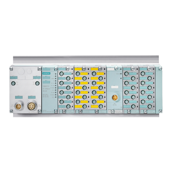
Product overview 3.3 Properties Properties Article number 6ES7516-2PN00-0AB0 (CPU 1516pro-2 PN) 6ES7194-4AP00-0AA0 (Connection module CM CPU 2PN M12 7/8") View of the module The figure below shows the CPU 1516pro-2 PN. Figure 3-1 CPU 1516pro-2 PN CPU 1516pro-2 PN (6ES7516-2PN00-0AB0) Operating Instructions, 11/2019, A5E35873416-AC... - Page 20 Section Mounting and connecting • nection module CM CPU 2PN M12, 7/8". (Page 23) Operating instructions of the • ET 200pro Distributed I/O System (https://support.industry.siemens. com/cs/ww/en/view/21210852) Expansion width Max. 1.2 m (without module rack) Section Technical specifications (Page 119) PROFINET IO...
- Page 21 Function Manual S7-1500, S7-1200 / S120, G120 Using the trace and logic analyzer function (https://support.industry.siemens.com/cs/ww/en/view/64897128) Function Manual S7-1500/S7-1500T Motion Control (https://support.industry.siemens.com/cs/ww/en/view/109766459) Sizer (https://w3.siemens.com/mcms/mc-solutions/en/engineering-software/drive-design- tool-sizer/Pages/drive-design-tool-sizer.aspx) TIA Selection Tool (https://w3.siemens.com/mcms/topics/en/simatic/tia-selection-tool) Function Manual S7-1500/S7-1500T Axis functions (https://support.industry.siemens.com/cs/ww/en/view/109766462) Function Manual S7-1500/S7-1500T Synchronism functions (https://support.industry.siemens.com/cs/ww/en/view/109766464) CPU 1516pro-2 PN (6ES7516-2PN00-0AB0) Operating Instructions, 11/2019, A5E35873416-AC...
-
Page 22: Operator Control And Display Elements
Product overview 3.4 Operator control and display elements Operator control and display elements 3.4.1 Front view of the module Operator control and connection elements The figure below shows the operator controls and connection elements of the CPU 1516pro-2 PN. ① Status and error displays ②... -
Page 23: Mode Switch
Product overview 3.5 Mode switch Slot for the SIMATIC memory card Figure 3-3 Slot for the SIMATIC memory card CPU 1516pro-2 PN uses a SIMATIC memory card as the memory module. You can use the SIMATIC memory card as load memory or as a portable storage medium. The slot for the SIMATIC memory card is accessible on the front of the CPU after removing the connection module. -
Page 24: Mounting And Connecting
You can find detailed information on mounting and connecting an ET 200pro in the corresponding sections of the ET 200pro operating instructions (http://support.automation.siemens.com/WW/view/en/21210852). In the sections below, you will learn the differences and special requirements for setup of an ET 200pro with the CPU 1516pro-2 PN. - Page 25 6. Mount the electronic modules, power modules and motor starters. You can find information in the ET 200pro operating instructions (http://support.automation.siemens.com/WW/view/en/21210852). 7. Mount the termination module (see ET 200pro operating instructions (http://support.automation.siemens.com/WW/view/en/21210852) for information on this). CPU 1516pro-2 PN (6ES7516-2PN00-0AB0) Operating Instructions, 11/2019, A5E35873416-AC...
-
Page 26: Connecting The Connection Module Cm Cpu 2Pn M12 7/8
Mounting and connecting 4.3 Connecting the connection module CM CPU 2PN M12 7/8" Connecting the connection module CM CPU 2PN M12 7/8" Introduction Connect the supply voltages and PROFINET to the connection module CM CPU 2PN M12, 7/8". The 1st PROFINET interface (X1) is equipped with an internal PROFINET switch. - Page 27 Mounting and connecting 4.3 Connecting the connection module CM CPU 2PN M12 7/8" X2 P1 M12 circular socket (with female contact insert) for connection of PROFINET X1 P1 R M12 circular socket connector (with socket insert) for connection of PROFINET R: Ring port for configuring a ring topology with media redundancy X1 P2 R M12 circular socket connector (with socket insert) for connection of PROFINET...
- Page 28 Mounting and connecting 4.3 Connecting the connection module CM CPU 2PN M12 7/8" Pin assignment of the M12 connector M12 circular sockets X1 P1 R and X1 P2 R: ● If autonegotiation is activated, then the M12 circular socket has the switch assignment (MDI-X).
- Page 29 Mounting and connecting 4.3 Connecting the connection module CM CPU 2PN M12 7/8" M12 circular socket X2-P1: Autocrossing is always active. As a result, the M12 circular socket has either a device assignment (MDI) or switch assignment (MDI-X). View of M12 connector, d- Terminal MDI (device assignment) MDI-X (switch assignment)
- Page 30 Mounting and connecting 4.3 Connecting the connection module CM CPU 2PN M12 7/8" Connecting M12 and 7/8" connectors 1. Press the M12 and 7/8" connection plugs into the corresponding circular sockets on the connection module CM CPU 2PN M12, 7/8". Ensure that the connector and socket are properly engaged.
-
Page 31: Connecting An Rj45 Socket
Mounting and connecting 4.4 Connecting an RJ45 socket Connecting an RJ45 socket Introduction You can connect, for example, a programming device to the RJ45 socket of the CPU. The PROFINET interface is equipped with an internal switch that allows PROFINET nodes to be connected directly. - Page 32 Mounting and connecting 4.4 Connecting an RJ45 socket Pin assignment of the RJ45 connector The assignment corresponds to the Ethernet standard for an RJ45 connection plug. RJ45 socket X1 P3: ● If autonegotiation is activated, then the RJ45 socket has the switch assignment (MDI-X). ●...
-
Page 33: Wiring And Circuit Diagram
Mounting and connecting 4.5 Wiring and circuit diagram Wiring and circuit diagram The figure below shows the wiring and circuit diagram of the CPU 1516pro-2 PN. ① Infeed of electronics/encoder supply 1L+ and load voltage supply 2L+ (X3) ② Loop-through of electronics/encoder supply 1L+ and load voltage supply 2L+ (X4) ③... -
Page 34: Configuring
STEP 7 (TIA Portal) as of V14 STEP 7 online help Reference You can find an overview of the most important documents and links to STEP 7 in an FAQ on the Internet (https://support.industry.siemens.com/cs/de/de/view/65601780/en). CPU 1516pro-2 PN (6ES7516-2PN00-0AB0) Operating Instructions, 11/2019, A5E35873416-AC... -
Page 35: Configuring The Cpu
Configuring 5.2 Configuring the CPU Configuring the CPU 5.2.1 Reading out the configuration Introduction When there is a connection to an existing CPU, you can load the configuration of this CPU, including present modules, from the device into your project using the "Hardware detection" function. - Page 36 Configuring 5.2 Configuring the CPU Procedure for reading out an existing configuration 1. Create a new project and configure an "Unspecified ET200pro Plus CPU". Figure 5-1 Unspecified ET200pro Plus CPU in the device view Note To open the "Hardware detection for PLC_x" dialog, click the "Detect" link. An alternative procedure is described in Step 2 and Step 3.
- Page 37 Configuring 5.2 Configuring the CPU 2. In the device view (or network view), select the "Hardware detection" command in the "Online" menu. Figure 5-2 Hardware detection in the Online menu STEP 7 opens the "Hardware detection for PLC_x" dialog box. CPU 1516pro-2 PN (6ES7516-2PN00-0AB0) Operating Instructions, 11/2019, A5E35873416-AC...
- Page 38 Configuring 5.2 Configuring the CPU 3. In the "Hardware detection for PLC_x" dialog box, click "Refresh". Then, select the CPU and click "Detect". Figure 5-3 Hardware detection dialog box CPU 1516pro-2 PN (6ES7516-2PN00-0AB0) Operating Instructions, 11/2019, A5E35873416-AC...
- Page 39 Configuring 5.2 Configuring the CPU Result of the hardware detection STEP 7 has read out the hardware configuration including the modules and transferred them to your project. STEP 7 assigns a valid default parameter assignments for all modules. You can change the parameter assignment subsequently. Figure 5-4 Result of the hardware detection in the device view Note...
-
Page 40: Address Assignment
Configuring 5.2 Configuring the CPU Reference You can find additional information on configuring the CPU / I/O modules and the individual settings in the STEP 7 online help. 5.2.2 Address assignment 5.2.2.1 Addressing - overview Introduction In order to address the automation components or modules, they must have unique addresses. - Page 41 Configuring 5.2 Configuring the CPU Hardware identifier STEP 7 automatically assigns a hardware identifier (HW identifier) for identification and addressing of modules and submodules. The HW identifier is used, for example, for diagnostics alarms or for instructions, to identify the faulty module or the addressed module. Figure 5-6 Example of a hardware identifier from STEP 7 The "System constants"...
-
Page 42: Addressing Digital Electronic Modules
Configuring 5.2 Configuring the CPU 5.2.2.2 Addressing digital electronic modules Introduction The following section describes the addressing of the digital electronic modules. You need the addresses of the channels of the digital electronic module in the user program. Addresses of the digital electronic modules The address of an input or output of a digital electronic module is composed of the byte address and the bit address. - Page 43 Configuring 5.2 Configuring the CPU Example of the assignment of addresses to channels (digital electronic module) The following figure shows how the addresses of the individual channels of the digital electronic module 16 DI DC 24 V arise. ① Channels 0 to 7; byte address: Module start address ②...
-
Page 44: Addressing Analog Electronic Modules
Address space 16 DI DC 24 V Reference You can find additional information on addressing and address allocation in the operating instructions of the ET 200pro distributed I/O system (https://support.industry.siemens.com/cs/ww/en/view/21210852) and in the STEP 7 online help. 5.2.2.3 Addressing analog electronic modules Introduction The following section describes the addressing of analog electronic modules. - Page 45 Configuring 5.2 Configuring the CPU Example of the assignment of addresses to channels (analog electronic module) The following figure shows how the addresses of the individual channels of the analog electronic module 4 AI RTD High Feature are determined when the module has the start address 256.
-
Page 46: Process Images And Process Image Partitions
Address space 4 AI RTD High Feature Reference You can find additional information on addressing and address allocation in the operating instructions of the ET 200pro distributed I/O system (https://support.industry.siemens.com/cs/ww/en/view/21210852) and in the STEP 7 online help. 5.2.3 Process images and process image partitions 5.2.3.1... -
Page 47: Assign Process Image Partitions To An Ob
Configuring 5.2 Configuring the CPU 32 process image partitions By means of process image partitions, the CPU synchronizes the updated inputs/outputs of particular modules with defined user program sections. For the CPU 1516pro-2 PN, the overall process image is subdivided into up to 32 process image partitions (PIP). -
Page 48: Update Process Image Partitions In The User Program
I/O access also writes the process image. This prevents a subsequent output of the process image from again overwriting the value written by direct access. Reference Additional information on process image partitions is available found in the function manual, Cycle and response times (https://support.industry.siemens.com/cs/ww/en/view/59193558). CPU 1516pro-2 PN (6ES7516-2PN00-0AB0) Operating Instructions, 11/2019, A5E35873416-AC... -
Page 49: Basics Of Program Execution
Basics of program execution Events and OBs Response to triggers The occurrence of a trigger results in the following reaction: ● If the event comes from an event source to which you have assigned an OB, this event triggers the execution of the assigned OB. The event enters the queue according to its priority. - Page 50 Basics of program execution 6.1 Events and OBs Types of event sources Possible priorities (default Possible OB Default system Number of OBs priority) numbers reaction Rack error 2 to 26 (6) Ignore 0 or 1 MC servo 17 to 26 (25) Not applicable 0 or 1 MC pre-servo...
- Page 51 Basics of program execution 6.1 Events and OBs OB priority and runtime behavior If you have assigned an OB to the event, the OB has the priority of the event. The CPU supports the priorities 1 (lowest priority) to 26 (highest priority). The following items are essential to the execution of an event: ●...
-
Page 52: Asynchronous Instructions
Basics of program execution 6.2 Asynchronous instructions Asynchronous instructions Introduction In program processing, a differentiation is made between synchronous and asynchronous instructions. The "synchronous" and "asynchronous" properties relate to the temporal relationship between the call and execution of the instruction. The following applies to synchronous instructions: When the call of a synchronous instruction is complete, execution of the instruction is also complete. - Page 53 Basics of program execution 6.2 Asynchronous instructions Parallel processing of asynchronous instruction jobs A CPU can process several asynchronous instruction jobs in parallel. The CPU processes the jobs in parallel under the following conditions: ● Jobs for an asynchronous instruction are started while other jobs for that instruction are still running.
- Page 54 Basics of program execution 6.2 Asynchronous instructions Status of an asynchronous instruction An asynchronous instruction shows its status via the block parameters STATUS/RET_VAL and BUSY. Many asynchronous instructions also use the block parameters DONE and ERROR. The figure below shows the two asynchronous instructions WRREC and CREATE_DB. ①...
- Page 55 Basics of program execution 6.2 Asynchronous instructions Summary The table below provides you with an overview of the relationships described above. It shows in particular the possible values of the output parameters if execution of the instruction is not complete after a call. Note You must evaluate the relevant output parameters in your program after each call Table 6- 3...
- Page 56 Basics of program execution 6.2 Asynchronous instructions Extended instructions: maximum number of simultaneously running jobs Table 6- 4 Maximum number of simultaneous jobs for asynchronous extended instructions and low- er-level instructions used Extended instructions CPU 1516pro-2 PN Distributed I/O RDREC RD_REC WRREC WR_REC...
- Page 57 Basics of program execution 6.2 Asynchronous instructions Extended instructions CPU 1516pro-2 PN Data block functions CREATE_DB READ_DBL WRIT_DBL DELETE_DB File handling FileReadC FileWriteC Basic instructions: maximum number of simultaneously running jobs Table 6- 5 Lower-level instructions used for asynchronous basic instructions Basic instructions CPU 1516pro-2 PN Array DB...
- Page 58 Basics of program execution 6.2 Asynchronous instructions Table 6- 7 Lower-level instructions used for asynchronous instructions for MODBUS TCP MODBUS TCP CPU 1516pro-2 PN MB_CLIENT uses TSEND, TUSEND, TRCV, TURCV, TCON, TDISCON MB_SERVER uses TSEND, TUSEND, TRCV, TURCV, TCON, TDISCON Table 6- 8 Maximum number of simultaneously running jobs for asynchronous instructions for S7 communication.
- Page 59 Basics of program execution 6.2 Asynchronous instructions Table 6- 10 Maximum number of simultaneously running jobs for asynchronous instructions for OPC UA. OPC_UA CPU 1516pro-2 PN OPC_UA_Connect OPC_UA_Disconnect OPC_UA_NamespaceGetIndexList OPC_UA_NodeGetHandleList OPC_UA_NodeReleaseHandleList OPC_UA_TranslatePathList OPC_UA_ReadList 50 (maximum 5 per connection) OPC_UA_WriteList 50 (maximum 5 per connection) OPC_UA_MethodGetHandleList OPC_UA_MethodReleaseHandleLi OPC_UA_MethodCall...
-
Page 60: Protection
● Deactivation of the OPC UA server (you can find additional information on the security mechanisms for OPC UA servers in the Communication (https://support.industry.siemens.com/cs/de/de/view/59192925/en) Function Manual) ● Deactivation of the time synchronization via an NTP Server ● Deactivation of the PUT/GET communication... -
Page 61: Configuring Access Protection For The Cpu
Protection 7.2 Configuring access protection for the CPU Configuring access protection for the CPU Introduction The CPU offers four different access levels to limit access to specific functions. By setting up the access levels and the passwords for a CPU, you limit the functions and memory areas that are accessible without entering a password. - Page 62 Protection 7.2 Configuring access protection for the CPU Properties of the access levels Each access level allows unrestricted access to certain functions without entering a password, e.g. identification using the "Accessible devices" function. The CPU's default setting is "No restriction" and "No password protection". In order to protect access to a CPU, you must edit the properties of the CPU and set up a password.
- Page 63 Protection 7.2 Configuring access protection for the CPU Configuring access levels To set the access levels for the CPU by means of parameter assignment, follow these steps: 1. Open the properties of the CPU in the Inspector window. 2. Select the "Protection & Security" area. A table with the possible access levels appears in the Inspector window.
-
Page 64: Using The User Program To Set Additional Access Protection
You can find additional information about this access level in the description of the fail-safe system SIMATIC Safety Programming and Operating Manual SIMATIC Safety - Configuring and Programming (https://support.industry.siemens.com/cs/ww/en/view/54110126). Using the user program to set additional access protection Access protection by means of the user program There is another option to access protection via the display. -
Page 65: Know-How Protection
Protection 7.4 Know-how protection Know-how protection Application You can use know-how protection to protect one or more OB, FB or FC blocks as well as global data blocks in your program from unauthorized access. Enter a password to restrict access to a block. The password offers high-level protection against unauthorized reading or manipulation of the block. - Page 66 Protection 7.4 Know-how protection Global data blocks and array data blocks You protect global data blocks (global DBs) from unauthorized access with know-how protection. If you do not have the valid password, you can read the global data block but not change it.
- Page 67 Protection 7.4 Know-how protection Opening know-how protected blocks To open a know-how protected block, follow these steps: 1. Double-click the block to open the "Access protection" dialog. 2. Enter the password for the know-how protected block. 3. Click "OK" to confirm your entry. Result: The know-how-protected block opens.
- Page 68 Protection 7.4 Know-how protection 3. Clear the "Hide code (Know-how protection)" check box. Figure 7-4 Removing block know-how protection (1) 4. Enter the password. Figure 7-5 Removing block know-how protection (2) 5. Click "OK" to confirm your entry. Result: Know-how protection for the selected block has been canceled. CPU 1516pro-2 PN (6ES7516-2PN00-0AB0) Operating Instructions, 11/2019, A5E35873416-AC...
-
Page 69: Copy Protection
Protection 7.5 Copy protection Copy protection Application The copy protection allows you to protect your program against unauthorized duplication. Copy protection allows you to link the program or the blocks to a specific SIMATIC memory card or CPU. Through the association with the serial number of a SIMATIC memory card or CPU, you make the use of this program or block only possible in combination with a specific SIMATIC memory card or CPU. - Page 70 Protection 7.5 Copy protection 4. If STEP 7 is to automatically insert the serial number during loading (dynamic binding), then activate the option "Serial number is inserted when downloading to a device or a memory card". To link the use of a block/program additionally to the input of a password, assign a password using the "Define password"...
-
Page 71: Commissioning
The following free software tools support you in commissioning: ● SIEMENS PRONETA in commissioning PROFINET systems. ● SIMATIC automation tool in commissioning the CPU 1516pro-2PN.. You can find more information on SIEMENS PRONETA and the SIMATIC Automation Tool in the section AUTOHOTSPOT CPU 1516pro-2 PN (6ES7516-2PN00-0AB0) -
Page 72: Procedure For Commissioning The Et 200Pro Distributed I/O System With Cpu
Commissioning 8.2 Procedure for commissioning the ET 200pro distributed I/O system with CPU Procedure for commissioning the ET 200pro distributed I/O system with CPU 8.2.1 Introduction PROFINET IO Requirements ● The CPU is in the "Factory settings" state or has been reset to factory settings (see section Resetting the CPU to factory settings (Page 101)). -
Page 73: Cpu As Io Controller
Commissioning 8.2 Procedure for commissioning the ET 200pro distributed I/O system with CPU 8.2.2 CPU as IO controller Configuration example The following configuration example shows the use of the ET 200pro distributed I/O system with the CPU 1516pro-2 PN as an IO controller. Figure 8-1 CPU 1516pro-2 PN as IO controller CPU 1516pro-2 PN (6ES7516-2PN00-0AB0) - Page 74 See ... Mounting ET 200pro (with CPU 1516pro-2 PN) Section Mounting and connecting (Page 23) Operating instructions ET 200pro Distributed I/O System (https://support.industry.siemens.com/cs/ww/en/view/ 21210852) Inserting the SIMATICmemory card into IO controller Section Inserting/replacing SIMATIC memory card (Page 76) Connecting the ET 200pro...
-
Page 75: Cpu As I-Device
Commissioning 8.2 Procedure for commissioning the ET 200pro distributed I/O system with CPU 8.2.3 CPU as I-device Configuration example The following configuration example shows the use of the ET 200pro distributed I/O system with the CPU 1516pro-2 PN as an I-device. Figure 8-2 CPU 1516pro-2 PN as I-device CPU 1516pro-2 PN (6ES7516-2PN00-0AB0) - Page 76 See ... Mounting ET 200pro (with CPU 1516pro-2 PN) Section Mounting and connecting (Page 23) Operating instructions ET 200pro Distributed I/O System (https://support.industry.siemens.com/cs/ww/en/view/ 21210852) Inserting the SIMATIC memory card into the I-device Section Inserting/replacing SIMATIC memory card (Page 76) Connecting the ET 200pro...
-
Page 77: Inserting/Replacing Simatic Memory Card
Commissioning 8.3 Inserting/replacing SIMATIC memory card Inserting/replacing SIMATIC memory card The SIMATIC memory card as memory module The CPU uses a SIMATIC memory card as a memory module. You can use the SIMATIC memory card as load memory or as a portable storage medium. Note An inserted SIMATIC memory card is required to operate the CPU. - Page 78 After POWER ON, the CPU automatically performs a memory reset. Reference You can find additional information on the SIMATIC memory card in the function manual Structure and use of the CPU memory (https://support.industry.siemens.com/cs/de/en/view/59193101) and in the Appendix Accessories/spare parts (Page 136). CPU 1516pro-2 PN (6ES7516-2PN00-0AB0) Operating Instructions, 11/2019, A5E35873416-AC...
-
Page 79: Operating Modes Of The Cpu
Commissioning 8.4 Operating modes of the CPU Operating modes of the CPU 8.4.1 Operating modes of the CPU Introduction Operating states describe the behavior of the CPU at a specific time. The following operating states are possible via the mode selector: ●... - Page 80 Commissioning 8.4 Operating modes of the CPU Points to note ● All outputs are disabled or react according to the parameter settings for the respective module: They provide a substitute value as set in the parameters or retain the last value output and bring the controlled process to a safe operating mode.
- Page 81 Commissioning 8.4 Operating modes of the CPU Configuring startup behavior You configure the behavior of the CPU in the Startup group of the CPU properties. Setting the startup behavior To set the startup characteristics, follow these steps: 1. Select the CPU in the device view of the hardware network editor of STEP 7. 2.
-
Page 82: Stop Mode
Commissioning 8.4 Operating modes of the CPU Example for the "Comparison preset to actual configuration" parameter "Startup CPU only if compatible" The pin assignment and all electrical and functional properties must match. "Startup CPU even if mismatch" The CPU also starts with the following differences: - An analog output module is inserted instead of a configured digital input module. -
Page 83: Operating Mode Transitions
Commissioning 8.4 Operating modes of the CPU Reference Additional information about cycle and response times is available in the Function Manual Cycle and response times (https://support.industry.siemens.com/cs/ww/en/view/59193558). 8.4.5 Operating mode transitions Operating modes and operating mode transitions The following figure shows the operating modes and the operating mode transitions:... - Page 84 Commissioning 8.4 Operating modes of the CPU Operating mode transitions Effects ③ STOP → STARTUP The CPU switches to "STARTUP" mode if: The CPU clears the non-retentive memory, and resets the content of The hardware configuration and program • non-retentive DBs to the start values of blocks are consistent.
-
Page 85: Cpu Memory Reset
Commissioning 8.5 CPU memory reset CPU memory reset 8.5.1 Introduction Basics of a memory reset The CPU must be in STOP mode for a memory reset. A memory reset returns the CPU to the "initial state". Memory reset means: ● An existing online connection between your programming device/PC and the CPU is terminated. -
Page 86: Automatic Memory Reset
Commissioning 8.5 CPU memory reset Result after memory reset The following table provides an overview of the contents of the memory objects after memory reset. Table 8- 4 Memory objects after memory reset Memory object Contents Actual values of the data blocks, instance data blocks Initialized Bit memories, timers and counters Initialized... - Page 87 Commissioning 8.5 CPU memory reset Procedure using the mode selector Note Memory reset ↔ Reset to factory settings The procedure described below also corresponds to the procedure for resetting to factory settings: • Selector operation with inserted SIMATIC memory card: CPU executes a memory reset •...
-
Page 88: Backing Up And Restoring The Cpu Configuration
Commissioning 8.6 Backing up and restoring the CPU configuration Backing up and restoring the CPU configuration Backup from online device You may make changes in the operation of your plant. For example, you may add new devices, replace existing ones or adapt the user program. If these changes result in undesirable behavior, you can restore the plant to an earlier state. - Page 89 The emergency address (emergency IP address) of a CPU is intended for diagnostic and download functions, e.g. when the CPU is no longer accessible via the IP protocol after a wrong project is downloaded. For information on the emergency address, please refer to the Communication (https://support.industry.siemens.com/cs/ww/de/view/59192925/en) function manual. Storage of multilingual project texts When you configure a CPU, texts of different categories result, e.g.
- Page 90 You can find information on reading out the memory usage of the CPU and the SIMATIC memory card in the Structure and Use of the CPU Memory (https://support.industry.siemens.com/cs/de/de/view/59193101/en) Function Manual. You can find information on parameter assignment of multilingual project texts in STEP 7 in the STEP 7 online help.
-
Page 91: Identification And Maintenance Data
Commissioning 8.7 Identification and maintenance data Identification and maintenance data 8.7.1 Reading out and entering I&M data I&M data Identification and maintenance data (I&M data) is information saved on the module. The data ● Read-only (I data) or ● Readable/writable (M data) Identification data (I&M0): Manufacturer information about the module that can only be read. - Page 92 During the loading of the hardware configuration, the I&M data is also loaded. Reading I&M data via the Web server The procedure is described in detail in the Web server (https://support.industry.siemens.com/cs/ww/en/view/59193560) Function Manual. CPU 1516pro-2 PN (6ES7516-2PN00-0AB0) Operating Instructions, 11/2019, A5E35873416-AC...
-
Page 93: Data Record Structure For I&M Data
Explanation Identification data 0: (data record index AFF0 hex) VendorIDHigh Read (1 byte) This is where the name of the manufac- turer is stored (42 = SIEMENS AG). VendorIDLow Read (1 byte) Order_ID Read (20 bytes) 6ES71516-2PN00-0AB0 Article number of module (e.g. CPU) - Page 94 Commissioning 8.7 Identification and maintenance data Identification data Access Default Explanation IM_REVISION_COUNTER Read (2 bytes) 0000 Provides information about parameter changes on the module (not used) IM_PROFILE_ID Read (2 bytes) 0000 Generic Device IM_PROFILE_SPECIFIC_TYPE Read (2 bytes) 0001 0003 Modules IM_VERSION Read 0101...
-
Page 95: Example: Read Out Firmware Version Of The Cpu With Get_Im_Data
Commissioning 8.7 Identification and maintenance data 8.7.3 Example: Read out firmware version of the CPU with Get_IM_Data Automation task You want to check whether the modules in your automation system have the current firmware. The firmware version of the modules can be found in the I&M0 data. The I&M0 data are the basic information of a device and contain information such as the manufacturer ID, article number, serial number and the hardware and firmware version. - Page 96 Commissioning 8.7 Identification and maintenance data 4. Connect the "Get_IM_Data" instruction as follows: Figure 8-7 Example: Calling the "Get_IM_Data" instruction 5. Call the "Get_IM_Data" instruction in the user program. Result The "Get_IM_Data" instruction has stored the I&M 0 data in the data block. You can view the I&M0 data online in STEP 7, for example with the "Monitor all"...
-
Page 97: Shared Commissioning Of Projects
Commissioning 8.8 Shared commissioning of projects Shared commissioning of projects Team Engineering Within the framework of Team Engineering, several users work in parallel on a project and access the CPU from different engineering systems. The users can work on individual parts of a master project independently of one another at the same time. -
Page 98: Maintenance
CPU is retained after performing the firmware update. Requirement You have downloaded the file(s) for the firmware update from Siemens Industry Online Support Product Support (https://support.industry.siemens.com/cs/ww/en/ps). ● Select the ET 200pro category from the product tree for this: Automation Technology >... - Page 99 Maintenance 9.1 Firmware update From this position, navigate to the specific type of module that you want to update. To continue, click on the "Software downloads" link under "Support". Save the desired firmware update files. Figure 9-2 Selecting the software downloads ●...
- Page 100 Maintenance 9.1 Firmware update Installation of the firmware update WARNING Impermissible plant states possible Installation of the firmware update causes the CPU to switch to STOP mode. STOP may affect the operation of an online process or a machine. Unexpected operation of a process or a machine can lead to fatal or severe injuries and/or to material damages.
- Page 101 If you use the SIMATIC memory card subsequently as a program card, delete the firmware update files (including JobFile "S7_JOB.S7S") manually. Procedure: via the integrated Web server The procedure is described in the Web server (https://support.industry.siemens.com/cs/ww/en/view/59193560) Function Manual. CPU 1516pro-2 PN (6ES7516-2PN00-0AB0) Operating Instructions, 11/2019, A5E35873416-AC...
-
Page 102: Resetting The Cpu To Factory Settings
9.2 Resetting the CPU to factory settings Procedure online via the SIMATIC Automation Tool The procedure is described in the SIMATIC Automation Tool (https://support.industry.siemens.com/cs/de/en/view/98161300) manual (included in the SIMATIC Automation Tool). Reference You can find additional information on the procedure in the STEP 7 online help. - Page 103 Maintenance 9.2 Resetting the CPU to factory settings Procedure using the mode selector Make sure that the CPU is in STOP mode: The display of the CPU shows the STOP mode. The RUN/STOP LED lights up yellow. Note Reset to factory settings ↔ Memory reset The procedure described below also corresponds to the procedure for a memory reset: •...
- Page 104 Procedure using the SIMATIC Automation Tool The procedure is described in the SIMATIC Automation Tool (https://support.industry.siemens.com/cs/de/en/view/98161300) manual (included in the SIMATIC Automation Tool). Result after resetting to factory settings The following table provides an overview of the contents of the memory objects after the reset to factory settings.
- Page 105 Reference Additional information on "Reset to factory settings" can be found in the Structure and Use of the CPU Memory (https://support.industry.siemens.com/cs/ww/en/view/59193101) Function Manual in the section on memory areas and retentivity, and in the STEP 7 online help. For information on the memory reset of the CPU, refer to the section CPU memory reset (Page 84).
-
Page 106: Test And Service Functions
Test and service functions 10.1 Test functions Introduction You have the option of testing the operation of your user program on the CPU. You monitor signal states and values of tags, and preassign tags with values so that you can simulate specific situations for program execution. - Page 107 Test and service functions 10.1 Test functions Testing with program status The program status allows you to monitor the execution of the program. You can hereby display the values of operands and the results of logic operations (RLO). This allows you to detect and fix logical errors in your program.
- Page 108 Test and service functions 10.1 Test functions Note Restrictions when testing with breakpoints • If you test with breakpoints, it is possible that the cycle time of the CPU is exceeded. • If you are using technology objects and test them with breakpoints, the CPU switches to STOP mode.
- Page 109 Test and service functions 10.1 Test functions Testing with watch tables The following functions are available in the watch table: ● Monitoring of tags With watch tables, you monitor the current values of individual tags of a user program or a CPU on the PG/PC and Web server.
- Page 110 Test and service functions 10.1 Test functions Testing with a force table The following functions are available in the force table: ● Monitoring of tags You can use force tables to have the current values of the individual tags of a user program or CPU displayed on the programming device or PC and on the Web server.
- Page 111 ● The trace function can be called from the CPU's folder in the project tree, under the name "Traces". For the testing with the trace functions, please also see the FAQs on the Internet (https://support.industry.siemens.com/cs/ww/en) . CPU 1516pro-2 PN (6ES7516-2PN00-0AB0) Operating Instructions, 11/2019, A5E35873416-AC...
- Page 112 You can find additional information on the test functions in the STEP 7 online help. Additional information about testing with trace functions is available in the Function Manual Using the trace and logic analyzer function (https://support.industry.siemens.com/cs/ww/en/view/64897128). CPU 1516pro-2 PN (6ES7516-2PN00-0AB0) Operating Instructions, 11/2019, A5E35873416-AC...
-
Page 113: Reading Out/Saving Service Data
Test and service functions 10.2 Reading out/saving service data 10.2 Reading out/saving service data Service data In addition to the contents of the diagnostics buffer, the service data contain numerous additional data points about the internal status of the CPU. If a problem occurs with the CPU that you cannot resolve with other methods, send the service data to our Service &... - Page 114 IP address of the CPU is not possible. For more information on reading out service data via a user-defined page, refer to the Web server (https://support.industry.siemens.com/cs/ww/en/view/64897128) function manual. Procedure using STEP 7 You can find more information on saving service data with the keyword "Saving service data"...
-
Page 115: Interrupts, Diagnostics, Error Messages And System Events
The following section describes the status and fault displays of the CPU 1516pro-2 PN. You can find more detailed information on "Interrupts" in the STEP 7 online help. You can find additional information on the topics of "Diagnostics" and "System alarms" in the Diagnostics (https://support.industry.siemens.com/cs/ww/en/view/59192926) function manual. CPU 1516pro-2 PN (6ES7516-2PN00-0AB0) -
Page 116: Status And Error Display Of The Cpu
Interrupts, diagnostics, error messages and system events 11.1 Status and error display of the CPU 11.1 Status and error display of the CPU LED display The figure below shows the LED displays of the CPU 1516pro-2 PN. ① RUN/STOP LED (yellow/green LED) ②... - Page 117 Interrupts, diagnostics, error messages and system events 11.1 Status and error display of the CPU Meaning of the RUN/STOP, ERROR and MAINTENANCE LEDs The CPU 1516pro-2 PN has three LEDs for displaying the current operating state and diagnostic status. The following table shows the meaning of the various combinations of colors of the RUN/STOP, ERROR and MAINTENANCE LEDs.
- Page 118 Interrupts, diagnostics, error messages and system events 11.1 Status and error display of the CPU Meaning of LINK RX/TX LED X1 P1, X1 P2 and X2 P1 each have a LINK RX/TX LED (yellow/green LED). Port X1 P3 has a LINK LED (green) and an RX/TX LED (yellow). The table below shows the various "LED scenarios"...
- Page 119 Interrupts, diagnostics, error messages and system events 11.1 Status and error display of the CPU Status display 24 V DC The 24 V DC LED lights up green when you have connected the load voltage supply 2L+. If the LED does not light up, check whether the power supply is switched on and the fuse is okay.
-
Page 120: Technical Specifications
ET 200pro distributed I/O system. You can find detailed information on the general technical specifications in the ET 200pro Distributed I/O System (https://support.industry.siemens.com/cs/ww/en/view/21210852) operating instructions. Technical specifications of the CPU 1516pro-2 PN The following table shows the technical specifications as of 11/2019. You will find a data sheet including daily updated technical specifications on the Internet (https://support.industry.siemens.com/cs/ww/en/pv/6ES7516-2PN00-0AB0/td?dl=en). - Page 121 Technical specifications Article number 6ES7516-2PN00-0AB0 Power Infeed power to the backplane bus 2.275 W Power loss Power loss, typ. 5.3 W Memory Number of slots for SIMATIC memory card SIMATIC memory card required Work memory 1 Mbyte integrated (for program) •...
- Page 122 Technical specifications Article number 6ES7516-2PN00-0AB0 1 Mbyte Size, max. • Number of free cycle OBs • Number of time alarm OBs • Number of delay alarm OBs • 20; With minimum OB 3x cycle of 500 µs Number of cyclic interrupt OBs •...
- Page 123 Technical specifications Article number 6ES7516-2PN00-0AB0 Data areas and their retentivity Retentive data area (incl. timers, counters, 512 kbyte; In total; available retentive memory for flags), max. bit memories, timers, counters, DBs, and tech- nology data (axes): 472 KB Flag 16 kbyte Number, max.
- Page 124 Technical specifications Article number 6ES7516-2PN00-0AB0 Clock synchronization supported • in AS, master • in AS, slave • on Ethernet via NTP • Interfaces Number of PROFINET interfaces Number of PROFIBUS interfaces 1. Interface Interface types 3; 2x M12 + 1x RJ45 Number of ports •...
- Page 125 Technical specifications Article number 6ES7516-2PN00-0AB0 PROFINET IO Controller Services – PG/OP communication – S7 routing – Isochronous mode – Direct data exchange Yes; Requirement: IRT and isochronous mode (MRPD optional) – – Yes; as MRP redundancy manager and/or MRP client; max. number of devices in the ring: 50 –...
- Page 126 Technical specifications Article number 6ES7516-2PN00-0AB0 PROFINET IO Device Services – PG/OP communication – S7 routing – Isochronous mode – Yes; as MRP redundancy manager and/or MRP – client; max. number of devices in the ring: 50 Yes; Requirement: IRT – MRPD Yes;...
- Page 127 Technical specifications Article number 6ES7516-2PN00-0AB0 PROFINET IO Controller Services – PG/OP communication – S7 routing – Isochronous mode – Direct data exchange – – – MRPD – PROFIenergy – Prioritized startup 32; In total, up to 1 000 distributed I/O devices –...
- Page 128 Technical specifications Article number 6ES7516-2PN00-0AB0 Interface types RJ 45 (Ethernet) 100 Mbps • Autonegotiation • Autocrossing • Industrial Ethernet status LED • Protocols Number of connections 128; Via integrated interfaces of the CPU Number of connections, max. • Number of connections reserved for •...
- Page 129 Technical specifications Article number 6ES7516-2PN00-0AB0 Web server Yes; Standard and user pages HTTP • Yes; Standard and user pages HTTPS • OPC UA Runtime license required • Yes; Data access (read, write), method call, cus- OPC UA client • tom address space –...
- Page 130 Technical specifications Article number 6ES7516-2PN00-0AB0 – Number of sessions, max. 100 000 – Number of accessible variables, max. 20 000 – Number of registerable nodes, max. – Number of subscriptions per session, max. 100 ms – Sampling interval, min. 200 ms –...
- Page 131 Technical specifications Article number 6ES7516-2PN00-0AB0 Test commissioning functions Joint commission (Team Engineering) Yes; Parallel online access possible for up to 8 engineering systems Status block Yes; Up to 8 simultaneously (in total across all ES clients) Single step Number of breakpoints Status/control Status/control variable •...
- Page 132 Technical specifications Article number 6ES7516-2PN00-0AB0 Supported technology objects Motion Control Yes; Note: The number of axes affects the cycle time of the PLC program; selection guide via the TIA Selection Tool or SIZER 2 400 Number of available Motion Control re- •...
- Page 133 Technical specifications Article number 6ES7516-2PN00-0AB0 Altitude during operation relating to sea level 5 000 m; Restrictions for installation altitudes > 2 Installation altitude above sea level, max. • 000 m, see manual Configuration Programming Programming language – – – – –...
- Page 134 Technical specifications Article number 6ES7194-4AP00-0AA0 Dimensions Width 90 mm Height 130 mm Depth 51 mm Weights Weight, approx. 560 g CPU 1516pro-2 PN (6ES7516-2PN00-0AB0) Operating Instructions, 11/2019, A5E35873416-AC...
-
Page 135: Dimension Diagram
Dimension diagram CPU 1516pro-2 PN with connection module CM CPU 2PN M12, 7/8" This section contains dimension drawings of the module mounted on various module racks. You must observe the dimensions when mounting in cabinets, control rooms, etc. Figure A-1 Dimension diagram - Rack, narrow CPU 1516pro-2 PN (6ES7516-2PN00-0AB0) Operating Instructions, 11/2019, A5E35873416-AC... - Page 136 Dimension diagram Figure A-2 Dimension diagram - Rack, compact CPU 1516pro-2 PN (6ES7516-2PN00-0AB0) Operating Instructions, 11/2019, A5E35873416-AC...
-
Page 137: Accessories/Spare Parts
Accessories/spare parts Order number of CPU and connection module Designation Article number CPU 1516pro-2 PN 6ES7516-2PN00-0AB0 Connection module CM CPU 2PN M12 7/8“ 6ES7194-4AP00-0AA0 Order numbers of accessories Designation Article number Preassembled cables and connectors: IE M12 connecting cable 0.3 m 6XV1870-8AE30 Trailable cable 0.5 m... - Page 138 Accessories/spare parts Designation Article number 7/8" connecting cable for power supply 0.3 m 6XV1822-5BH30 Trailable power cable, 5 x 1.5 mm 0.5 m 6XV1822-5BH50 Preassembled with 7/8" 180 ° connectors at both ends, • 1.0 m 6XV1822-5BH10 fixed lengths, 1 unit: 1.5 m 6XV1822-5BH15 2.0 m...
- Page 139 Accessories/spare parts Designation Article number PROFINET FC cable 6XV1840-2AH10 FC TP Standard Cable • 6XV1840-3AH10 FC TP Trailing Cable • 6XV1870-2D FC TP Trailing Cable GP • 6XV1840-4AH10 FC TP Marine Cable • 6XV1870-2F FC TP Torsion Cable • Energy Cable 6XV1830-8AH10 Trailable power cable, 5 x 1.5 mm Sold by the meter, min.
-
Page 140: Safety-Relevant Symbols
Safety-relevant symbols Safety-related symbols for devices without Ex protection The following table contains an explanation of the symbols located in your SIMATIC device, its packaging or the accompanying documentation. Symbol Meaning General warning sign Caution/Notice You must read the product documentation. The product documentation contains information about the potential risks and enable you to recognize risks and im- plement countermeasures. -
Page 141: Safety-Related Symbols For Devices With Ex Protection
Safety-relevant symbols C.2 Safety-related symbols for devices with Ex protection Safety-related symbols for devices with Ex protection The following table contains an explanation of the symbols located in your SIMATIC device, its packaging or the accompanying documentation. Symbol Meaning The assigned safety symbols apply to devices with Ex approval. You must read the product documentation. - Page 142 Safety-relevant symbols C.2 Safety-related symbols for devices with Ex protection Symbol Meaning For Zone 2 potentially explosive atmospheres, be aware that the device may only be used when it is installed in an enclosure with a degree of protection ≥ IP54. For Zone 22 potentially explosive atmospheres, be aware that the device may only be used when it is installed in an enclosure with a degree of protection ≥...
- Page 143 Glossary Actuator Actuators are, for example, power relays or contactors for switching on load devices or load devices themselves (e.g. directly controlled solenoid valves). Automation system Programmable logic controller for closed-loop and open-loop control of process chains in industrial processes and manufacturing technology. The automation system consists of different components and integrated system functions according to the automation task.
- Page 144 Glossary The CPU uses the integrated system power supply to supply the electronics of the modules via the backplane bus. The CPU contains the operating system and executes the user program. The user program is located on the SIMATIC memory card and runs in the work memory of the CPU.
- Page 145 Glossary Diagnostics interrupt See "Interrupt, diagnostic" Distributed I/O system System with I/O modules that are configured on a distributed basis, at a large distance from the CPU controlling them. Distributed I/O Electronic modules Electronic modules form the interface between the process and the automation system. There are digital input and output modules as well as analog input and output modules.
- Page 146 Glossary Functional ground The functional ground is a low-impedance current path between electric circuits and ground. It is not intended as a protective measure but rather, for example, for improvement of interference immunity. Ground Chassis ground refers to all interconnected inactive parts of equipment that are unable to carry hazardous voltage even in the event of a fault.
- Page 147 Glossary Interrupt The operating system of the CPU distinguishes between various priority classes that control the execution of the user program. These priority classes include interrupts, such as hardware interrupts. When an interrupt occurs, the operating system automatically calls an assigned organization block.
- Page 148 Glossary Isochronous mode Process data, transmission cycle via PROFINET IO and user program are synchronized to achieve maximum deterministic behavior. The input and output data of distributed I/O modules in the system is simultaneously acquired and simultaneously output. Isochronous real-time communication Synchronized transmission method for cyclic exchange of IRT IO data between PROFINET devices.
- Page 149 Glossary OPC UA OPC UA (OPC Unified Architecture) is a collection of standards for industrial communications. These standards describe a service-oriented architecture: ● Transport of data between machines ● Interfaces and semantics of data, for example, information about the data such as data type and object type.
- Page 150 Glossary Power module The power module (PM) opens a new potential group for the load voltage supply 2L+. Process image (I/O) The CPU transfers the values from the input and output modules to this memory area. At the start of the cyclic program, the CPU transfers the signal states of the input modules to the process image input.
- Page 151 Glossary PROFINET IO controller Device used to address connected I/O devices (e.g. distributed I/O systems). This means that: The IO controller exchanges input and output signals with assigned I/O devices. Often, the IO controller is the CPU on which the automation program runs. Real-time Real-time means that a system processes external events within a defined time.
- Page 152 Glossary Shared device IO device that makes its data available to multiple IO controllers. SNMP SNMP (Simple Network Management Protocol) is the standardized protocol for performing diagnostics on and assigning parameters to the Ethernet network infrastructure. In the office setting and in automation engineering, devices from a wide range of vendors on the Ethernet support SNMP.
- Page 153 Glossary Termination module The termination module terminates the ET 200pro distributed I/O system. The ET 200pro is not ready for operation without an inserted termination module. TIA Portal Totally Integrated Automation Portal The TIA Portal is the key to the full performance capability of Totally Integrated Automation. The software optimizes operating, machine and process sequences.
- Page 154 Index backing up and restoring, 87 Unspecified CPU, 35 Access levels, 60 7/8" circular socket, 21 Backup/restore contents, 87 7/8" connectors Interfaces, 19 Connecting, 29 LEDs, 115 Pin assignment, 28 Operator control and connection elements, 21 removing, 29 Properties, 19 unspecified, 35 View, 18 Accessible devices...
- Page 155 Index Interfaces, 26 Power modules, 24 IO controller, 17, 72 Process image IO device, 17 Inputs and outputs, 45 IP address, 84, 102, 103 Process image partition Isochronous mode, 47 updating, automatically, 46 PROFINET I-device, 74 Interfaces, 21, 26, 30 IO controller, 73 LAN, 26 Switch, 25...
- Page 156 Index Technology objects, 85, 87, 103 Termination module, 23 Test functions, 105 TIA Portal, (see STEP 7) Tool, 23, 26, 30, 101 Trace, 110 Unspecified CPU, 35 User program, 50, 76, 81 Access protection via, 63 Testing, 105 WAN, 26 Watch tables, 105, 108 Web server Firmware update via, 100...
Need help?
Do you have a question about the SIMATIC ET 200pro and is the answer not in the manual?
Questions and answers