Table of Contents
Advertisement
Quick Links
Advertisement
Table of Contents

Subscribe to Our Youtube Channel
Related Manuals for Universal Remote Control MSC-400


Summary of Contents for Universal Remote Control MSC-400
- Page 1 CCP Programming Manual MSC-400 Master System Controller...
- Page 2 The information in this manual may be subject to change without prior notice. Complete Control is a registered trademark of Universal Remote Control, Inc. Entertainment Made Simple is a trade- mark of Universal Remote Control, Inc. All other brand or product names are trademarks or registered trademarks of their respective companies or organizations.
- Page 3 Properties Window Model Designer Treeview USTOMIZING THE ORKSPACE All Windows in the Default Layout can be resized All Windows in the Default Layout can be Moved Around Windows Grouping /Placement Icon Using the Window Auto-Hide Features ROGRAMMING Complete Control Program MSC-400...
- Page 4 Table of Contents Prior Programming Knowledge Required Program Remote Control Devices First! Use the Program Menu Save a Device file and Import for faster programming Save the MSC-400 File,Then Return to Remote Programming – P MSC-400 S TEP BY ROGRAMMING A...
-
Page 5: Table Of Contents
Type in Section Title Table of Contents # 5 - C ROGRAM REATING ACRO ROUPS AND MART ACROS Macro Groups Adding a Macro Group and Smart Macros Smart Macro Window Programming Smart Macros A Typical Smart Macro Moving Commands in a Smart Macro Recording RS232 Commands in Smart Macros Converting RS232 Commands to a Smart Macro Group Adding Delays To Smart Macros... - Page 6 Type in Section Title Creating a Macro Group for Relay Commands Saving And Downloading A MSC-400 Project Downloading a CCP MSC-400 Project Dragging Triggers into CCP MX-6000 or MX-980 Editors ASCII RS-232 C SING YPER ERMINAL TO ODES Introducing HyperTerminal...
- Page 7 VS-1006 Voltage Power Sensor VID-6 Video Sensor Cable NSTALLATION System Design Device Control Capabilities And Behavior User Preferences MSC-400 Master System Controller RFX-250 RF Sensor VS-1006 Voltage Power Sensor VID-6 Video Sensor Cable ONNECTIONS Video or Voltage Sensors (1-6) Control Voltage Out/Switched AC Out (VS-1006)
- Page 8 Type in Section Title RF Out USB2 Keyboard Emulation Relay 1 NO (Normally Open) NC (Normally Closed) Relay 2 12V Out 12VDC Master/Slave Systems ROUBLESHOOTING...
- Page 9 Macro Programming. Once all IR codes are labeled and arranged the way you want, you save the file, switch to the MSC-400 tab and import all the codes as “Connected Devices”. After setting the routing and adding any RS-232 devices to the list of connected devices, you create a list of Smart Macro Names (Watch DVD, Watch Cable TV, Turn System Off), then program the macros.
-
Page 10: Acros
Up to three RFX-250 Sensors can be connected for extended RF Remote range in large systems RF Output allows expansion to a second MSC-400 for control of up to 22 devices or connection to a MRF Series Base Station for control of IR devices located away from the MSC-400 Two internal relays provide additional integration and control of screens, lifts, drapes, amplifiers, etc. - Page 11 5 The Ready to Install Window will open. Click on INSTALL. 6 The program will install and then show that installation has been completed. Click on FINISH. 7 Now plug in the MSC-400 to the USB port. A Found New Hardware pop up will appear in the sys- tem tray.
- Page 12 11 The next window will display “Please choose your search and installation options.” Select Don’t search and click Next. 12 HIghlight the URC USB Sync MSC-400 & 500 driver. Click Next. 13 The Hardware Installation window opens with a message that this driver has not passed Windows...
- Page 13 Type in Section Title Installing 14 A files needed window will follow. Click on the Browse button and navigate to C:\Program Files\Universal Remote Control, Inc\Complete Control Program\MSC-400\drivers\Windows XP\USB7210-2k.sys. Click Open then OK. 15 Once the driver finishes installing then click Finish.
- Page 14 Right clicking on a device or page activates a context menu. The MSC-400 Simulate View is used to navigate and to select a button to program, edit or record a macro.
- Page 15 Type in Section Title New Features Overview of the New Features of CCP MSC-400 Complete Control Program represents a full house philosophy to programming, giving you tools to quickly pro- gram multiple remotes and base stations in one file. In addition to a new philosophy, CCP also features a con- figure home section to quickly build remotes and base stations to many rooms in a home, and also integrates an indepth look at MSC400 connected Devices, Macro Groups, Smart Macros and a clickable simulator.
- Page 16 Type in Section Title New Features 2 Click on the Program tab and select “Configure Home” (House Designer) from the far left of the Program ribbon. This will open the System Configuration window: NOTE: Drag remotes or base stations on top of the room to add to room.
- Page 17 It’s contents will differ according to the selection. MSC-400 Simulator 1 Click on the blue IR/RS232, video, voltage and RF ID ports of the MSC-400 simulator to access and configure their properties windows. 2 The Properties windows will appear within the Properties/Tools menu. If the properties window is not visible click on the property tab or go to View and check the Properties box.
- Page 18 Model Designer Treeview 1 Within the Model Designer Treeview to the right, click on a Connected Device, Macro Group, Smart Macro or the MSC-400 2 Once the selection has been made it’s respective property window will open and allow configuration.
-
Page 19: Macro Groups
Type in Section Title New Features In the Macro Group property win- dow you can rename the Macro Group and designate to which base station or port the macro will be sent to. Macro Group The smart macro property window has the same features as the macro group window with the exception of the Macro Trigger Setting sec-... - Page 20 Customizing the Workspace Type in Section Title Type in Section Title Customizing the Workspace CCP has some unique layout features that allow you to customize your own personal layout. Here is the default layout: Home and Model Designer are on the left, the Simulator is in the middle, the Properties window is in the upper right and the Macro window is in the lower right.
- Page 21 Customizing the Workspace Type in Section Title Type in Section Title All Windows in the Default Layout can be resized To resize a window, move the mouse cursor to the side, top or bottom edge of the window. When you’re in the right place, the windows “Resize Window”...
- Page 22 Customizing the Workspace Type in Section Title Type in Section Title If you grab a window and drag it around the main layout, several new windows “Grouping/Placement Options” appear. In the example below. I have moved the “Button Properties” window away from its default position on the left side of the screen.
- Page 23 Customizing the Workspace Type in Section Title Type in Section Title Windows Grouping /Placement Icon Windows snap into place when you drag the cursor / title bar of the window you want to move, into one of the five options in the Windows Grouping Placement Icon. Move the “Button Properties”...
- Page 24 Customizing the Workspace Type in Section Title Type in Section Title Using the Window Auto-Hide Features CCP has another layout feature that allows you to Float, Dock, Automatically Hide or Permanently Hide a window. Right click on the down arrow in the window title bar, a drop down menu appears with the following choic- es: Floating, Dockable, Auto-Hide and Hide.
-
Page 25: Complete Control Program Msc
Before starting a MSC-400 Project, be sure all that you have completed programming Devices in the remote editor. It is much faster to import remote control devices than to create them from scratch in MSC-400 editor. Use the Program Menu The Program Menu is your lifeline to a fast, easy programming experience. - Page 26 Simply drag the triggers onto the remote buttons. For further details see page 55 for Dragging Triggers to CCP remote editors. TIP - Saving the MSC-400 Project with the same name as the Remote Project will help in being able to associ- ate remotes and MSCs as the number of MSC projects starts to increase.
- Page 27 Type in Section Title Type in Section Title Step by Step – Programming a Typical MSC-400 System Options - New or Existing Files DEFAULT (1 Remote, 1 Room)- Opens either in a MX-6000 or MX-980 with the option of choosing a graphical template.
- Page 28 6 First, drag and drop a desired room, ie Home Theater, below “Home” within the Configuration tree view. 7 Drag and drop a base station, such as the MSC-400, to the same room. 8 Highlight the MSC-400 base station then click on the Properties button located at the bottom left.
- Page 29 Saving your New File Type in Section Title Type in Section Title 9 The Base Station Model Properties window appears. 10 Name the Base Station. Example: “MSC-400FULL (Home Theater)” 11 Select an RF ID from the RF ID drop-down list. 12 If using a second base, check and choose the second RF ID.
- Page 30 Program Menu Step #1 - Import Remote Control Devices This step will import the IR Commands for the devices to be controlled by the MSC-400. All physically con- nected devices to the MSC-400 should be imported to the CCP MSC Editor. The remaining devices, which are not physically connected to the MSC-400, will be controlled locally by the remote control.
- Page 31 Program Menu Step #2 - Devices & Routing This section will assign each device to a dedicated IR output on the MSC-400. When assigned, the MSC-400 will ONLY send a Connected Device’s IR Commands to the IR PORT ASSIGNED. This gives much more precise control over the IR level delivered to the component and enables you to control identical components.
- Page 32 All Connected Devices will default to PORT: IR 1. Under the PORT # column, click IR 1 and select the appropriate PORT from the drop down list. NOTE - In a Master/Slave System, each MSC-400 can only control eleven Connected Devices. Port 12 is used as a Smart Macro Control Buss.
- Page 33 Type in Section Title Adding IR Devices Optional Step - Adding IR Devices Normally, you don’t need to add any devices, since you have already imported them from the remote control. Use this step should you need to control an IR device that is needed for macros but not needed on the remote control for the end user (for example a matrix video switcher).
- Page 34 Adding RS232 Devices Type in Section Title Adding RS232 Devices - Optional Step If your client’s system has a device that you intend to control via RS-232, here is how you add a new connect- ed device that is RS-232. For more information on RS-232, refer to the RS-232 section of this manual. 1 Follow steps 1 - 6 under Program Step #2 of Devices &...
- Page 35 Type in Section Title IR Database Program Menu Step # 3 - IR Database Using the IR Database - Discrete Codes and Toggles iscrete Codes and Toggles The Universal Remote database is unique in the industry because it includes “secret” discrete codes that are not on the actual remote controls for many components.
- Page 36 Type in Section Title IR Database 3 Select your base station from the Target model field. 4 Click on the Device drop down to select your device. 5 Click on the IR Data from drop down to select the type of device. 6 Select the manufacturer of the product from the Brand field.
- Page 37 Program Menu Step #4 - Serial Template Database Programming RS232 Devices RS232 Command strings can be used to control Connected Devices from a MSC-400. Unlike IR commands, where the remotes can output both IR and RF to control local devices directly, the RS232 commands must be programmed into the MSC-400 and triggered with RF Triggers or Sensed Triggers.
- Page 38 Coding RS232 Commands Type in Section Title To Manually Code RS232 Commands: 1 In CCP MSC Editor Model Designer Treeview, double click the Connected Device for which RS232 commands are to be added. Note: All RS232 devices are represented with an S in front of it and all IR devices are represented with a IR .
-
Page 39: Rs232 Repeat, Ramp Start And Ramp Speed
Name, Data Type and Command String in the appropriate boxes. Up to 1024 commands can be added. NOTE - To TEST manually encoded commands, the PC must be connected to the MSC-400 USB1Port. The MSC 400 serial port must be designated in the Device Properties window and also must be connected to the device using an appropriate RS232 CABLE. -
Page 40: Embedding Rs232 Commands In Smart Macros
Database for this function will not be modified. Repeat and Ramp will need to be cond for each use of the command. 7 To TEST the command, SAVE the Project, then DOWNLOAD the Project to the MSC-400 and test using the REMOTE. - Page 41 Macro Groups and Smart Macros Type in Section Title NOTE - Serial Port Settings must be downloaded to the MSC-400 before attempting to test Embedded RS232 Commands. Click Ok. The command will appear in the smart macro function list, where it can be moved and used in smart macros and if/else statements as with any other command.
-
Page 42: Adding A Macro Group And Smart Macros
Macro Groups and Smart Macros Type in Section Title NOTE - There are no absolutes in how a MSC-400 has to be programmed, so the following sections are sug- gestions and guidelines for Macro programming. Every system is different, every user has different preferences and each installer has a different perspective of how things can be done. -
Page 43: Smart Macro Window
11 The Macro Group and Smart Macros will appear at the bottom of the model designer treeview. Smart Macro Window The Smart Macro Window is where all programming for MSC-400 Smart Macros is done. IR and RS232 Commands, Delays, IF/ELSE Statements, Action Variables and all steps and conditions are cond in this window for System ON/OFF Macros, Source Select Macros, etc. -
Page 44: Programming Smart Macros
12 Action Variable – Click this Icon to add Action Variables to Smart Macros. Programming Smart Macros There are two ways that Smart Macros can be triggered in a MSC-400 System. * Normal Macro - A Normal Macro is triggered by an RF Trigger from a remote control. Normal Macros are typically used for System ON/OFF, Source Select and Favorite Channel Macros. -
Page 45: Moving Commands In A Smart Macro
Macros see section: MACRO GROUPS AND SMART MACROS and apply RS232 Commands the same way IR Commands are recorded, moved and used in IF/ELSE Statements within Smart Macros. Converting RS232 Commands to a Smart Macro Group In order for the MSC-400 to output RS232 commands from remote control button presses, RF Triggers must be... -
Page 46: Adding Delays To Smart Macros
RS232 commands. The RF Triggers will be programmed to the appropriate buttons on the remote which will then be able to send the triggers to the MSC-400. When the MSC-400 receives one of these triggers, it will output the associated RS232 command, in the same way it works with IR commands. -
Page 47: Favorite Channel Macros
Highlight the Delay and press Delete on the PC Keyboard. 6 Test the Smart Macro. With the PC connected to the MSC-400 using the included USB cable, click the Test Icon in the Smart Macro Window Tool BAR. The MSC will output the commands. Adjust command order and delay duration as needed. - Page 48 Type in Section Title To program Favorite Channel Macros: 1 In the CCP MSC-400 Editor Menu Bar, click Program, then click Make Smart Macro. 2 Add a New Group named Favorite Channels Cable(Satellite, etc), then add the names for the Favorite Channel Smart Macros to the list.
- Page 49 11 To Test, in Treeview, click the ‘+’ next to Favorite Channels Group to expand the list and click a Smart Macro in the list. The macro will appear in the Smart Macro window. 12 With the PC connected to the MSC-400 USB1 Port, click the Test button in the Smart Macro win- dow.
- Page 50 True Mode: If the “True Mode” radio button is selected, the macro will be issued every time the button is pressed. The IF Sensor: When the “Sensor” button is selected, the MSC-400 will sense the state of a device whether it is on or off via the video or voltage sensor and execute the macro.
-
Page 51: Programming If/Else Statements
“stupid” macro and a Smart one? Let’s take a look at how to program a Smart Macro in MSC-400 Editor: 1 Click on the red Record button, then record a standard macro with the macro steps you need from the Connected Devices. - Page 52 With these selections, when the Watch Cable TV Macro is triggered, the MSC-400 will look at Master Controller Sensor Input 1 to determine if the Cable box is OFF. If it is, the MSC-400 will output the TV Power Command.
-
Page 53: Programming Sensor Triggered Macros - Video And Voltage
9 Set the same voltage sensor configuration for the audio receiver as the cable box. 10 To Save, click on file within the CCP MSC editor Menu Bar then select Save. 11 To Test, download the MSC Project to the MSC-400. Also see Section: Programming Smart Macro Triggers to the Remote. -
Page 54: Toggle Macros
Macro Trigger Button is repeatedly pressed on the remote, the MSC-400 will cycle through the list, rather than having to press a separate button for each mode. This same type of programming can be used for favorite channels. If the user has multiple HBOs available, or just wants to cycle through a few select favorite channels to ‘see what’s on’, repeated presses of the Toggle Macro... -
Page 55: Action Variables
Variables enable the MSC-400 to track the status of a device or a user by “remembering” what state it/he/she is Think of them as a way for the MSC-400 to take notes while your client uses the system so that when your client presses a button, the MSC-400 can make a decision on the best thing to do in the Smart Macro. -
Page 56: An Example Of Action Variables At Work
2 If the client walks up to the device and powers it on manually or with the device’s original remote control, there is no way for the MSC-400 to track the change. Thus, it will be “out of sync”. Only you, the installer can eliminate this problem, by training the client to never use the front panel or original remote control to power on or off a variable tracked device. - Page 57 Type in Section Title Action Variables ing power so we’ve named the variable “Audio is ON”. This state can either be True or False, so the label is very descriptive. Now, click on the Add button. You could add as many variables as needed.
-
Page 58: Adding Relay Commands To Smart Macros
Adding Relay Commands to Smart Macros The MSC-400 has two Dry Contact Relays that can be used for a variety of functions such as opening and clos- ing drapes, operating lifts, screens or activating switched devices such as amplifiers, switched outlets, etc. -
Page 59: Embedding Relay Commands In A Smart Macro
Type in Section Title Relays Control IN on a Power Amplifier (it is also connected to the 12V Convenience Terminal on the MSC-400 as the source of the control voltage). The Relay configuration is Normally Open (NO). When the ON Command is issued, the Relay will close, 12V will be present on the mini plug and the amplifier will turn ON. - Page 60 5 In the Target block, select Relay Port 1 or 2 using the pull-down. (ex. Relay 1) 6 To Test the command, with the PC connected to the USB1 front port on the MSC-400, click the Test button. There should be an audile ‘click’ as the relay opens or closes in test mode.
- Page 61 Creating a Macro Group for Relay Commands In order to control the MSC-400 Relays directly from the remote, for functions such as opening and closing drapes, a Macro Group will need to be setup to create the RF Triggers to activate the Relays from the remote.
- Page 62 17 To Test a Relay command with a Timed Duration (with the PC connected to the MSC400 USB1 front port) click the Test button. There should be two audible clicks, from the MSC-400, equal to the value set in Minimum Press Time, indicating the relay is changing state.
-
Page 63: S Downloading A Ccp Msc-400 Project
21 Test from the remote by Pressing and Holding the appropriate buttons. Saving And Downloading A MSC-400 Proejct When all configuration and programming have been completed, the MSC-400 Project should be saved and downloaded to the MSC-400. 1 To Save, in the CCP MSC Editor Menu Bar click File, then Save. - Page 64 Programming Macro Triggers to CCP Remotes Smart Macro Triggers are individual commands sent by a remote to the MSC-400 to initiate the output of a Normal Macro. Once the MSC-400 has been configured, programmed and tested (and the MSC file is saved), the Smart Macro Triggers need to be dragged into the correct button on the remote control.
-
Page 65: U Sing H Yper T Erminal To T Est Ascii Rs-232 C Odes
While this document will show you how to set-up and use HyperTerminal it is not written as a primer on RS-232. For further details on what RS-232 is and how to use it in the MSC-400, please view our tutorial now available on the installer only website. - Page 66 Type in Section Title HyperTerminal 3 Create a name – We suggest RS-232 Testing – and then select an icon to use. Click on Ok, which will bring up a new option that asks you to select a phone number. We aren’t using a modem, so a phone number won’t be necessary.
- Page 67 RS-232 commands that are sent out by the MSC-400. Before we can start the testing process, there is one more thing you have to do. By default, feedback (status return messages) don’t appear in HyperTerminal.
-
Page 68: E How To Use Hyperterminal
* You can take one of the RS-232 output ports from the MSC-400 and plug that directly into your computer. This will allow you to see exactly what message the MSC-400 is sending to a device and verify that it is what you intended to happen. - Page 69 Type in Section Title PC KEYBOARD EMULATION As a convenience, a MSC-400 compatible remote can be programmed as a PC Keyboard emulator for alpha search commands when used with a Windows Media Center PC. The user should have a proper wireless key- board for use with the PC, but having alpha search capability from the remote allows additional control capa- bility without having to switch back and forth between the remote and keyboard.
- Page 70 PC Keyboard Emulation Type in Section Title 6 In Model Designer Treeview, click the Page 2 icon. PC Keyboard Emulator Page 2 7 Using the Button Editor, add the letters A-F to the individual buttons as shown in PC Keyboard Emulator Page 2 and click Save.
- Page 71 PC device. 15 Save the project and Download to the remote. See Section: Saving and Downloading a CCP Project for additional information. NOTE - The Media Server PC must be connected to the USB2 Port on the MSC-400 Rear Panel.
- Page 72 Master/Slave Systems Type in Section Title PROGRAMMING MASTER/SLAVE SYSTEMS Programming a Master/Slave System is essentially programming a system with two MSC-400s. Each Controller will be configured for the devices it is sensing and controlling, the main differences are, in Configure Home, MSC400 Properties controlled by the Master are set to Master and the devices sensed and controlled by the Slave are set to Slave.
- Page 73 Ports 7-11, then any RFID can be used for any remote and the Secondary RFID does not need to be set in Step 9 Within the Serial Port Setting page, select (check mark) the Port 12 to Slave MSC-400 box. The Port 12 Setting line will gray out.
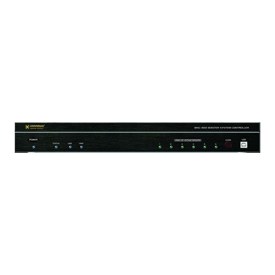
- Page 74 2 Status LED – One, blue LED flashes when an RF signal from a MSC compatible remote is received and understood via the RFX-250 Sensor. 3 USB1 LED – One, blue LED illuminates to indicate that a PC is connected to the MSC-400 front panel USB1 Programming Port.
- Page 75 Master/Slave System. POLARITY: TIP=+5VDC; RING=data; SLEEVE=GND. 13 RF Out – 3.5 mono mini jack connects to the RF IN on a MSC-400 Slave unit in Master/Slave Systems using two MSC-400 Controllers. This jack can also connect to the RF IN on a MRF Series Basestation for control of system components located away from the main component area.
-
Page 76: Msc-400 T Op P Anel F Eatures
MSC-400 Top Panel 20 IR Output Levels – Twelve, rotary controls allow adjustment of corresponding IR emitter outputs 1- 12 on the MSC-400 Rear Panel. These pots do not adjust output level on jacks 7-12 when they are cond for RS232 control. - Page 77 22 RF Out (Mini Jack) – One three-circuit 3.5 mono mini jack provides power to the RFX-250 and sends understood RF commands to the MSC-400. This jack can be connected to either of the RF IN’s on the MSC-400 rear panel. POLARITY: TIP=+5VDC; RING=data; SLEEVE=GND.
- Page 78 26 Sensor Plug – One four-circuit 3.5 mono mini plug connects to one of the Video or Voltage Sensor Inputs on the MSC-400 rear panel. 27 Power LED – One red LED illuminates to indicate the VS-1006 is properly connected to and pow- ered from the MSC-400.
- Page 79 The VID-6 Video Sensor Cable is a special cable assembly that connects the composite video output of a con- nected device to a Video or Voltage Sensor Input on the MSC-400 rear panel. This method provides excellent conditional status sensing with devices that feature a switched composite video output. Not all devices turn the composite video output off when in standby –...
- Page 80 On/Off commands can be handled in MSC-400 programming. If a device does not have discrete On/Off commands, the next question is: How is the MSC-400 going to know if it is on or off? If a device has a Control Out or switched AC outlet, a VS-1006 can provide voltage power sensing for the On/Off status of that device.
- Page 81 RF IN terminals to extend the range of the coverage area. If the MSC-400 is centrally located, it may be desirable to have one RFX-250 at or near the MSC-400 and install a second at one end of the residence and a third on the other end to provide complete coverage for RF reception from the remote controls.
- Page 82 6 Slide the RFX-250 over the mounting plate until it clicks into the clip track and locks into position. VS-1006 Voltage Power Sensor The VS-1006 should be located near the MSC-400, within the 10’ length of the attached sensor cable. It should be placed in a location that allows easy access for making connections or troubleshooting if necessary.
- Page 83 4 Once the system has been powered up, the VS-1006 power LED should illuminate red. 5 To test voltage sensing, turn the sensed device on. The Video or Voltage Sensor LED on the MSC-400 Front Panel with the same number as the sensor input should illuminate green. Turn the Sensed Device Off.
- Page 84 TIP - If the IR eye is not obvious, refer to the owner’s manual or shine a small flash light into the display window on the device front panel to locate the eye. 2 Carefully pull the sleeved emitter wire back to the MSC-400 and connect it to the appropriate ir or rs232 programmable output jack.
- Page 85 Some devices will use other types of connectors such as RJ45 and mini jacks. Custom cables can be made using the pin-out for the MSC-400 jacks as shown in Typical System. Please refer to the device owner’s manual for the pin-out of RS232 Terminals that are not DB9 connectors.
- Page 86 1 When using two MSC-400’s in a Master/Slave system, use one of the included 10’ 4-Circuit mini- mini cables, to connect the RF out on the MSC-400 Master to the RF in on the MSC-400 Slave. The RF out on the Master unit can also be connected to the RF in on a MRF-350 or MRF-300 for control of devices located away from the MSC-400.
- Page 87 2 For a device that requires external control voltage: Connect a jumper (24-14 AWG two conductor stranded wire, typical) from the 12V out ter- minal on the MSC-400 Rear Panel to the Relay 1 COM terminal as shown in Normally Closed (Relay 2 Shown).
- Page 88 Master/Slave Systems Two MSC-400 Controllers can be linked together for control of up to 22 Connected Devices via IR (22) or IR and RS232 (the number of IR devices will vary by system, 10 RS232 devices max). Other than using IR/RS232 Port 12 for a Smart Macro Control Buss between Controllers, both Controllers are fully capable of all func- tions.
- Page 89 MSC Does Not Output RS232 Commands Connected Device Configuration a) Confirm RS232 Command programming for Connected Devices b) Confirm RS232 Port Configuration c) Confirm Serial Port Settings have been downloaded to the MSC-400 RS232 Cable Connection a) Confirm connection to proper RS232 Port Voltage Sensor...
- Page 90 Troubleshooting TROUBLESHOOTING Slave Controller Does Not Output Commands Master/Slave Connections a) Confirm RF connection between controllers b) Confirm Port 12 connection between controllers Master/Slave Configuration a) Confirm Master/Slave RFID Configuration b) Confirm Slave Connected Device Configuration to Slave Macro Execution Smart Macros do not maintain device ON/OFF a) Confirm Smart macro structure for all com- sync with system status...
- Page 91 Universal Remote Control, Inc. 500 Mamaroneck Avenue Harrison, NY 10528 Phone: 914.835.4484 Fax: 914.835.4532 Technical Support: 1.800.901.0800 www.universalremote.com ©2009 Universal Remote Control, Inc. CCP MSC-400 Manual 2Rev 4...
Need help?
Do you have a question about the MSC-400 and is the answer not in the manual?
Questions and answers