Table of Contents
Advertisement
Quick Links
Advertisement
Table of Contents

Related Manuals for Zeiss Humphrey Matrix 800


Summary of Contents for Zeiss Humphrey Matrix 800
- Page 1 Humphrey Matrix ■ Model 800 User Manual...
- Page 2 Trademarks FORUM, HFA, Humphrey, and Matrix are either registered trademarks or trademarks of Carl Zeiss Meditec, Inc. in the United States and/or other countries. HP and PCL are registered trademarks of Hewlett-Packard Company. All other trademarks used in this document are the property of their respective owners.
-
Page 3: Table Of Contents
(1) Introduction ..................1 • Chapter Overview ..................1 • Instrument Overview ..................1 • Intended Use ....................2 • Indications for Use..................2 • Humphrey Matrix User Manual..............4 • System Hardware..................5 • Instrument Components..................6 • Underside Connectors................... 7 •... - Page 4 • Screens Overview..................2 • F1: Main Menu....................2 • F2: View Patients ..................4 • F3: Recall Tests....................5 • F4: File Functions..................6 • F5: System Settings..................7 • F6: Help ......................8 (4) Test Results and Reliability Measures..........1 •...
- Page 5 • Conflict Resolution..................... 4 • Database Restore ..................4 • Restore User Settings..................5 (8) Networking Configuration............... 1 • Chapter Overview ..................1 • Network Capabilities ..................1 • Risks of Internet Connectivity ............... 2 • Approved Third Party Hardware and Software..........2 •...
- Page 6 (11) Specifications ..................1 • Instrument Specifications ................1 • Chinrest Module Specifications..............1 • Environmental Specifications................ 2 • Visual Field Test Specifications..............2 (12) Legal Notices..................1 (A) DICOM Gateway................. 1 • Chapter Overview ..................1 • Overview....................... 1 •...
-
Page 7: Instrument Overview
Introduction (1) Introduction Chapter Overview Topics covered in this chapter: • Instrument Overview, page • Humphrey Matrix User Manual, page • System Hardware, page • External Device Equipment, page 1-10 • Instrument Installation, page 1-11 • Tips to Avoid Damage, page 1-11 •... -
Page 8: Intended Use
Introduction • No corrective (trial) lens needed up to +/- 3 diopters; patients can usually wear their own correction or none at all (see Patient Correction on page 5-11). • No eye patch is needed for the untested eye—it is automatically occluded •... - Page 9 Introduction There is a general requirement that the patient be able to sit upright and be able to place their face in the forehead rest of the instrument (with or without supplemental human or mechanical support). Part of the Body The Humphrey Matrix physically interacts with the patient’s forehead and chin.
-
Page 10: Humphrey Matrix User Manual
Humphrey Matrix User Manual Carl Zeiss Meditec designed this User Manual to serve as a detailed usage and reference guide for the Matrix instrument. The Matrix User Manual instructs you in the procedures for testing the patient, creating and managing patient records, and reviewing and printing tests. -
Page 11: System Hardware
Introduction Other chapters and appendices include: (10) Maintenance, (11) Specifications, (12) Legal Notices, (A) DICOM Gateway, (B) OfficeMate PMS Instructions, and Data Transfer Using a Text Conventions • “Click” means “left-click”. • Chains of menu or button items are indicated with the use of the “>” symbol between items. -
Page 12: Instrument Components
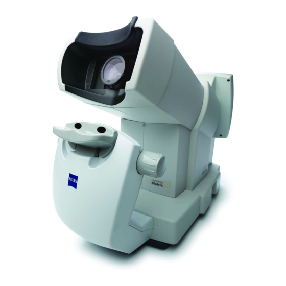
Introduction Instrument Components Figure 1-1 Matrix Model 800 Hardware Components 1. Patient Visor 4. USB Port 7. Patient Response Button and PRB holder 2. Operator Screen 5. Track Pad 3. CD-R/W Drive 6. Keyboard The instrument has a sliding Patient Visor that aids in isolating the eye for testing and automatically occludes the opposite (untested) eye. -
Page 13: Underside Connectors
Introduction Figure 1-2 Instrument – Patient Side 1. Patient Forehead Rest 2. Sliding Patient Visor 3. Power Switch Underside Connectors On the underside of the base of the Matrix are the computer ports described below. Network Connector The network connector is a standard RJ-45 (10/100 Base T) Ethernet port for connecting to local area networks (LANs). -
Page 14: Patient Response Button Connector
Introduction the instrument for connecting a USB printer. The front USB port should be dedicated to removable USB storage devices. CAUTION: Connect ONLY the USB keyboard and integrated track pad supplied with the instrument or an approved replacement to a USB port on the bottom of the instrument. - Page 15 Introduction markers indicating chin placement for each eye—white marker for left eye and blue marker for right eye. The knobs on either side adjust the height of the chinrest. Figure 1-4 Matrix Model 800 with Chinrest Module 1. Chinrest Height-adjustment knob 3.
-
Page 16: External Device Equipment
Introduction 1-10 Matrix Instrument Software Carl Zeiss Meditec pre-installs all software necessary to operate the Matrix System instrument. Software updates with installation instructions may be provided on CD or on the Matrix section of our website (www.meditec.zeiss.com/matrix). Data Storage We recommend archiving data to a network file server. For non-networked environments, an external USB hard drive can be used. -
Page 17: Instrument Installation
• In case of emergency related to the instrument, unplug the power cord from the wall outlet and call for service immediately. For Carl Zeiss Meditec customer service: In the U.S., call 800-341-6968. Outside the U.S., contact your local CZM distributor. -
Page 18: Product Compliance
CAUTION: It is possible that Matrix functionality may be adversely affected by the presence, installation, or use of third party software on the same computer. The user, and not Carl Zeiss Meditec, assumes all risks associated with third party software. -
Page 19: Safety
CAUTION: If a table is available, do not reconfigure system components on the table, nor add non-system devices or components to the table, nor replace original system components with substitutes not approved by Carl Zeiss Meditec. Such actions could result in failure of the table height adjustment mechanism, instability of the table, tipping and damage to the instrument, and injury to operator and patient. -
Page 20: Electromagnetic Compatibility (Emc)
Introduction 1-14 WARNING: SERVICE or REPAIR to be performed by QUALIFIED, AUTHORIZED PERSONNEL ONLY. There are NO USER SERVICEABLE PARTS INSIDE the Humphrey Matrix instrument. Disassembly of the instrument presents a possible ELECTRICAL SHOCK hazard and will VOID the warranty. If the unit fails, contact CZM for instructions. - Page 21 Introduction 1-15 Guidance and manufacturer’s declaration – electromagnetic immunity The Matrix is intended for use in the electromagnetic environment specified below. The customer or user of the Matrix should assure that it is used in such an environment. Immunity Test IEC 60601 test level Compliance level Electromagnetic environment - guidance...
- Page 22 Introduction 1-16 Guidance and manufacturer’s declaration – electromagnetic immunity The Matrix is intended for use in the electromagnetic environment specified below. The customer or user of the Matrix should assure that it is used in such an environment. Immunity Test IEC 60601 test level Compliance level Electromagnetic environment –...
-
Page 23: Symbols And Labels
Introduction 1-17 Recommended separation distances between portable and mobile RF communications equipment and the Matrix The Matrix is intended for use in an electromagnetic environment in which radiated RF disturbances are controlled. The customer or the user of the Matrix can help prevent electromagnetic interference by maintaining a minimum distance between portable and mobile RF communications equipment (transmitters) and the Matrix as recommended below, according to the maximum output power of the communications equipment. -
Page 24: Protective Packing Symbols
Introduction 1-18 European Conformity Disposal of the Product within the EU. Do not dispose via domestic waste disposal system or communal waste disposal facility. Protective Packing Symbols The protective packing symbols specify the handling requirements and the transport and storage conditions. Handling Requirements Transport and Storage Conditions Fragile, Handle with Care... -
Page 25: Instrument Disposition
1-19 Instrument Disposition When it comes time to upgrade the Matrix, please contact Carl Zeiss Meditec to inquire about trade-in or upgrade values we may offer. Should you not wish to trade in the instrument, please dispose of it in accordance with local and national electrical and electronic equipment recycling requirements. - Page 26 Introduction 1-20 Humphrey Matrix User Manual 2660021138935 Rev. F 2015-11...
-
Page 27: Setting Up The Instrument
Setting Up the Instrument (2) Setting Up the Instrument Chapter Overview Because of its light weight and small size, you can set up your Matrix instrument virtually anywhere in your office. • Refer to (9) Printer Configuration and to the information provided in the printer box for printer setup, use, maintenance and service information. -
Page 28: Preparation For Use
Setting Up the Instrument 6. Set the instrument on the chinrest assembly, as shown on the assembly instruction sheet. 7. Check the equipment received with the packing list to ensure all parts are included. Aligning the instrument with your patient is important for good test results. It is recommended to use the chinrest module with the instrument. -
Page 29: System Settings
Setting Up the Instrument System Settings System Settings are provided to allow you to customize the operation of the Humphrey Matrix instrument to meet your preferences and practice needs (see Figure 2-1). The Screen is comprised of eight screens: G YSTEM ETTINGS ENERAL... -
Page 30: System Settings - General
Setting Up the Instrument System Settings – General Date Format: Select the date format preferred from the drop down list. The date format selected is used everywhere the date is displayed or printed. Time Format: Select either 12-Hour or 24-Hour (military) time formats. The time format selected is used everywhere the time is displayed or printed. -
Page 31: System Settings - Testing
Setting Up the Instrument System Settings – Testing Figure 2-2 System Settings – Testing Screen Default Test: Select the test that is run when Enter is pressed in the M (F1) Screen, or when Run Test is selected from the V (F2) Screen. -
Page 32: System Settings - Backup
Setting Up the Instrument Default First Eye to Test: Select the first eye for testing when a test is run. You can also choose the eye for testing from the T Screen. ESTING Catch Trials: Select individual catch trials to turn either On or Off. Refer to the Reliability Measures on page... - Page 33 Setting Up the Instrument System Settings – Export Figure 2-3 System Settings – Export Screen Default Export Location: The default export location sets the location when Export is selected as an Automatic End of Test Action on the Testing Screen (System Settings (F5) > System Settings –...
- Page 34 Note: On a PC, it may be possible to view and analyze Matrix data using third party software. Beyond the instructions here, Carl Zeiss Meditec does not support the import of Matrix data to a PC; neither do we specify third party software you can use on a PC to view and analyze Matrix data, nor support its use.
- Page 35 Setting Up the Instrument System Settings – Backup Figure 2-4 System Settings – Backup Screen Default Backup Location: Select the default location for database backups when Perform Backup is selected from the M (F1) Screen (full database backup), and for automatic test backup at end of test.
-
Page 36: Usb Storage Devices
Setting Up the Instrument 2-10 Note: If you remove a shared folder that is currently selected as a Network Share, the first shared folder in the S list will be selected as the Network Share. If there are AVED HARES no other shared folders in the list, the Network Share will be disabled. -
Page 37: Selecting A Folder On A Usb Storage Device
Setting Up the Instrument 2-11 Selecting a Folder on a USB Storage Device To select a folder on the USB storage device, select the browse button ( ) for the selected device and then select the folder you want as the default USB location (Figure 2-5). -
Page 38: Safely Remove A Usb Storage Device
Setting Up the Instrument 2-12 Safely Remove a USB Storage Device Double-click the USB Ports icon ( ) in the lower right of all screens to see the USB S TORAGE 2-7). To safely remove a USB storage device, click the Eject button Screen (Figure EVICES... -
Page 39: General Operation
General Operation (3) General Operation Chapter Overview Topics covered in this chapter include: • Powering Up the Instrument , page • Powering Down the Instrument, page • Keyboard and Track Pad Operations, page • Screens Overview, page • F1: Main Menu, page F2: View Patients, page... -
Page 40: Keyboard And Track Pad Operations
General Operation Keyboard and Track Pad Operations The keyboard functions in a similar manner to normal computer keyboards. Pressing ALT and the underlined letter or number on the button selects the button (English language only). The Track Pad controls the cursor like a mouse. The left button is used to select items or buttons. - Page 41 All Humphrey Matrix data stored on the hard disk, a CD, a network file server or computer, a USB drive, and/or any other storage device are your records, and it is your responsibility to preserve the integrity of these data files. Carl Zeiss Meditec is not responsible for loss of patient data.
-
Page 42: F2: View Patients
General Operation F2: View Patients Figure 3-2 View Patients Screen – Local Database The V (F2) Screen is where new patients are added or existing patient entries in ATIENTS the database are searched, recalled, and revised. If you have DICOM Gateway enabled and are connected to a Modality Worklist provider, you can import patient demographic and scheduled exam information from a Modality Worklist. -
Page 43: F3: Recall Tests
General Operation F3: Recall Tests Figure 3-3 Recall Tests Screen The R (F3) Screen is where individual tests in the database are searched by ECALL ESTS patient or test information. Once the desired individual tests are selected, you can then recall, delete, print, or save the test results. -
Page 44: F4: File Functions
General Operation F4: File Functions Figure 3-4 File Functions Screen The F (F4) Screen is where the patient test database is backed up or imported, UNCTIONS merged, or restored. User settings can also be restored from a database backup. The F Screen is where available software upgrades of the Humphrey Matrix system UNCTIONS software can be performed. -
Page 45: F5: System Settings
General Operation F5: System Settings Figure 3-5 System Settings Screen The S (F5) Screen provides the operator with the ability to customize the YSTEM ETTINGS configuration of the Humphrey Matrix Visual Field Instrument by changing default system settings to meet your preferences and practice needs. The S Screen is YSTEM ETTINGS... -
Page 46: F6: Help
General Operation F6: Help Figure 3-6 Help Screen – Basic The H (F6) Screen is where the user may view the instrument’s system information including system software version (SBC Software Version). When needed, the Install Software , Calibration, Diagnostics, and Logging, functions are also accessed from the Help Screen. - Page 47 Test Results and Reliability Measures (4) Test Results and Reliability Measures Chapter Overview This chapter discusses test results and reliability measures. Topics covered in this chapter include: Visual Field Tests Summary, page • • Screening Tests, page • Threshold Tests, page •...
-
Page 48: Test Results And Reliability Measures
Test Results and Reliability Measures Screening Tests All of the Humphrey Matrix visual field FDT screening tests are supra-threshold tests meaning that they test at specific age-corrected contrast values determined by the normative database probability levels. Select the probability levels to use for screening for general clinical use to maximize sensitivity (-5 uses the 5% probability level) or for population based screening to maximize specificity (-1 uses the 1% probability level). - Page 49 Test Results and Reliability Measures Figure 4-1 Full Threshold Test Example Humphrey Matrix User Manual 2660021138935 Rev. F 2015-11...
- Page 50 Test Results and Reliability Measures For the N-30-F FDT full threshold test, the instrument utilizes a staircase threshold strategy known as a Modified Binary Search (MOBS). The Humphrey Matrix utilizes a four-reversals rule (N-30-F) for determining the threshold level. The range of possible threshold level values for the raw data (patient threshold scores) is between 0 dB Maximum Contrast (lowest patient sensitivity) and 56 dB Minimum Contrast (highest patient sensitivity).
- Page 51 Test Results and Reliability Measures To the right of the total deviation plots are two additional plots, labeled Pattern Deviation. These are similar to the total deviation plots, except that here the test results have been adjusted for any changes in the height of the measured hill of vision caused, for example, by cataracts or small pupils.
-
Page 52: Reliability Measures
Test Results and Reliability Measures there is significant loss in one part of the field and not in others. MD is best inter- preted in relation to the Total and Pattern Deviation plots. Pattern Standard Deviation (PSD) is a measurement of the degree to which the shape of the patient's measured field departs from the normal, age-corrected reference field. -
Page 53: Chapter Overview
Patient Testing (5) Patient Testing Chapter Overview To prepare to perform a visual field test, follow the simple procedure sections outlined below: • Test Set-Up, page • Patient Selection, page • Administering the Test, page 5-10 • Patient Correction, page 5-11 •... -
Page 54: Mwl - Today's Patients (Worklist Patients Scheduled For Today)
Patient Testing • MWL - Today’s Patients: From a Modality Worklist if you have DICOM Gateway enabled and are connected to a Modality Worklist provider, see DICOM Gateway Configuration on page A-2. See MWL - Today’s Patients (Worklist Patients Scheduled for Today) on page 5-2. - Page 55 Patient Testing provider (see DICOM Gateway Configuration on page A-3), select MWL - Today’s Patients from the Source drop-down menu. The Modality Worklist is automatically searched for patients scheduled for an exam for this Matrix (AE Title) on today’s date. A Matrix is identified by its Local AE Title entered on the DICOM G Screen (see Local...
-
Page 56: Worklist Patient Conflicts
Patient Testing anywhere in the exam’s row to see patient and scheduled exam details. Select the OK button on the E Screen to open the T Screen (Figure 5-8). ELECTION ESTING Figure 5-3 Patient and Exam Details Screen Note: If DICOM Gateway is enabled, editing patient information imported (or merged into an existing patient) from a DICOM system is disabled. -
Page 57: Mwl - Custom Query (Search The Worklist)
Patient Testing MWL - Custom Query (Search the Worklist) Figure 5-4 View Patients Screen – MWL - Custom Query Using MWL - Custom Query allows you to provide specific query parameters before displaying scheduled patients exams for this instrument. Input of patient data is not required if scheduling via Modality Worklist. - Page 58 Patient Testing Table 5-1 DICOM Standard Modality Code Descriptions Modality Code Description (blank) All modalities Ophthalmic Visual Field Ophthalmic Photography Ophthalmic Mapping Ophthalmic Tomography Other If needed, you can select the Default button to reset all the query fields to their default values. Once you have entered your desired criteria, select the Search button to initiate the query.
-
Page 59: Local Database (Search Local Database Or Add New Patient)
Patient Testing Local Database (Search Local Database or Add New Patient) Figure 5-5 View Patients Screen – Local Database Search Local Database You can recall or add a new patient from the local database on the instrument. If Local Database is selected in the Source drop-down menu, you can search for an existing patient already in the local database by typing the patient’s last name, first name, DOB (date of birth), Patient ID, or Issuer of Patient ID to initiate a search of the local database. - Page 60 Patient Testing the DICOM system to edit patient information on the instrument.If you are using a DICOM system, you should only change the Patient ID, Patient Name, or Date of Birth on the DICOM system, and not on the Matrix, to avoid patient conflicts. Select the desired patient by clicking on its row to highlight it, and then select the Run Test button to open the T Screen...
-
Page 61: Omlocal (Officemate Practice Management Software)
Patient Testing Note: If DICOM Gateway is used, it is recommended to enter data in all fields (Last Name, First name, Date of Birth, Patient ID, and Issuer of Patient ID) to minimize the possibility of patient conflicts in the DICOM System. Once the required patient information is entered, select the Add Patient button. -
Page 62: Administering The Test
Patient Testing 5-10 column by clicking between columns to activate the resizing tool ( ), holding down the left track pad button, and dragging to resize. If needed, you can select the Reset button to clear your entered search criteria. Once you have entered your desired criteria, select the Search button to initiate the query. -
Page 63: Patient Correction
Patient Testing 5-11 The T Screen (Figure 5-8) allows you to prepare the patient for the test and to ESTING confirm or modify the testing configuration selections, if needed, prior to performing the visual field test. The status box under the chart on the right side of the screen shows that the Pre-test Demo is running. -
Page 64: Patient Seating And Position
Patient Testing 5-12 Patient Seating and Position 1. Confirm the Patient Visor is in the correct position so that the Patient Eyepiece is aligned with the eye to be tested. 2. Hand the Patient Response button to the patient and check that the patient is relaxed. 3. -
Page 65: Testing
Patient Testing 5-13 “There is a brief flash just before the actual test begins.” [select Start Test button.] “The test is beginning now. Please remember to keep looking at the black spot in the center of the screen at all times during the test.” It is a good idea to encourage the patient throughout the testing to help ensure proper patient alignment, fixation, and attention. - Page 66 Patient Testing 5-14 You may enter “Notes” or Patient “Information” at any time before, during or after the test by selecting the appropriate tab. You may want to note how well the patient maintained fixation during the test, for example. At the completion of each eye test, the results are displayed on the Operator LCD.
-
Page 67: Chapter Overview
Viewing and Printing Tests (6) Viewing and Printing Tests Chapter Overview This chapter discusses viewing and printing tests. Sample tests are shown at the end of the chapter. Topics covered in this chapter include: • Viewing Test Results, page • Printing/Saving Test Results, page •... - Page 68 Viewing and Printing Tests If you selected multiple entries, choose the pull-down menu at the top of the T ETAILS Screen (see Figure 6-2) to select a specific test from all selected, or use the Previous or Next buttons at the bottom of the T Screen to cycle through the selected tests.
-
Page 69: Printing/Saving Test Results
Viewing and Printing Tests chart. Select the More >> button at the upper right of the screen to view additional test information generated by the instrument. Printing/Saving Test Results When viewing a test, you may select Print to obtain printed test results, select Delete to permanently delete the selected test from the instrument’s database or select Save As... -
Page 70: Printing Tests
Viewing and Printing Tests To set the location, select the CD-R/W, DICOM (if DICOM Gateway is enabled), Network Share, or USB radio button. For Network Share and USB, select a location from the corresponding drop-down menu. For Network Share, you must have previously added network shared folders to select them here (see Add Network Shared Folders on page... -
Page 71: Moving/Reassigning Tests
Viewing and Printing Tests Moving/Reassigning Tests To move tests to a different working folder (see System Settings – Testing on page for information on the default working folder), or to reassign tests to a different Figure 6-4). patient, select the test(s) you want and then select Edit Test... (see Figure 6-4 Edit Test Dialog Move to Folder Select Move to Folder... -
Page 72: Reassign Tests
Viewing and Printing Tests Reassign Tests Select Reassign Test on the Edit Test dialog to reassign the test(s) to a different patient. Select OK to confirm and the Select Patient dialog appears 6-6). (Figure Figure 6-6 Reassign Test – Select Patient Dialog Search for the patient you want by entering patient information in the fields provided—the patient list is updated automatically. -
Page 73: Analysis
Viewing and Printing Tests Analysis The Analysis button in the V (F2) Screen only provides an Overview Plot. Select ATIENTS Figure 6-7). Overview to generate an Overview Plot (see Figure 6-7 Select Overview Plot To generate an Overview Plot for the selected patient, select a test type from Test Selection and an eye from Select Eye. -
Page 74: Sample Tests
Viewing and Printing Tests Sample Tests Figure 6-8 N-30-5 FDT Screening Humphrey Matrix User Manual 2660021138935 Rev. F 2015-11... - Page 75 Viewing and Printing Tests Figure 6-9 N-30-1 FDT Screening Humphrey Matrix User Manual 2660021138935 Rev. F 2015-11...
- Page 76 Viewing and Printing Tests 6-10 Figure 6-10 24-2-5 FDT Screening Humphrey Matrix User Manual 2660021138935 Rev. F 2015-11...
- Page 77 Viewing and Printing Tests 6-11 Figure 6-11 24-2-1 FDT Screening Humphrey Matrix User Manual 2660021138935 Rev. F 2015-11...
- Page 78 Viewing and Printing Tests 6-12 Figure 6-12 N-30-F FDT Threshold Humphrey Matrix User Manual 2660021138935 Rev. F 2015-11...
- Page 79 Viewing and Printing Tests 6-13 Figure 6-13 24-2 FDT Threshold Humphrey Matrix User Manual 2660021138935 Rev. F 2015-11...
- Page 80 Viewing and Printing Tests 6-14 Figure 6-14 30-2 FDT Threshold Humphrey Matrix User Manual 2660021138935 Rev. F 2015-11...
- Page 81 Viewing and Printing Tests 6-15 Figure 6-15 10-2 FDT Threshold Humphrey Matrix User Manual 2660021138935 Rev. F 2015-11...
- Page 82 Viewing and Printing Tests 6-16 Figure 6-16 Macula FDT Threshold Humphrey Matrix User Manual 2660021138935 Rev. F 2015-11...
- Page 83 Viewing and Printing Tests 6-17 Figure 6-17 24-2 FDT Threshold Overview Humphrey Matrix User Manual 2660021138935 Rev. F 2015-11...
- Page 84 Viewing and Printing Tests 6-18 Humphrey Matrix User Manual 2660021138935 Rev. F 2015-11...
-
Page 85: Database Management
Database Management (7) Database Management Chapter Overview The F (F4) Screen provides database management capabilities. A single testing UNCTIONS database is used on the Humphrey Matrix so all your visual field test results are available in the working database. Topics covered in this chapter include: •... - Page 86 Database Management To make a backup copy of the testing (default) database: 1. Select File Functions (F4) to display the F Screen (Figure 7-1). UNCTIONS Figure 7-1 File Functions Screen 2. In the Database Backup section, select the browse button ( ) to select a backup location.
-
Page 87: Database Import / Merge
Database Management Note: For Network Share, you must have previously added network shared folders to select them here (see Add Network Shared Folders on page 8-14). For information on USB storage devices see USB Storage Devices on page 2-10. Note: The backup location is remembered until instrument shutdown. 4. -
Page 88: Conflict Resolution
Database Management Conflict Resolution In the File Functions menu under Database Import / Merge and Restore Database, you have the option of setting the Conflict Resolution to Auto or Manual. If Conflict Resolution is set to Manual and there are two of the same tests for a patient, or two of the same patients, one in the database and one on the restore media, the operator will receive a prompt to decide which results are placed in the database. -
Page 89: Restore User Settings
Database Management Shared Folders on page 8-14). For information on USB storage devices see Storage Devices on page 2-10. Note: Use Database Import if it is coming from another instrument. Note: The restore location is remembered until instrument shutdown. 4. Select OK. 5. - Page 90 Database Management Note: Printer settings are not backed up and therefore not restored. Note: Information on the Upgrade System function is found under Upgrade System on page 10-5. Humphrey Matrix User Manual 2660021138935 Rev. F 2015-11...
-
Page 91: Chapter Overview
With an Ethernet port, the Matrix 800 instrument is capable of connecting to local area networks for data storage and printing. With DICOM Gateway software enabled, the Matrix 800 can connect to a DICOM system, such as Carl Zeiss Meditec’s FORUM™ (see (A) DICOM Gateway). -
Page 92: Risks Of Internet Connectivity
Repairs necessitated by the attempt to use a non-approved device are not covered under warranty. Note: Carl Zeiss Meditec does not provide technical support for the use of unapproved third party hardware or software. Using the Shared Network Folders Using shared network folders is recommended in offices that have a local area network, especially if you have multiple Matrix instruments. -
Page 93: Network File Server System Requirements
Networking Configuration Network File Server System Requirements Operating System • Windows® XP Professional, 32-bit, Service Pack 3 • Windows 2000 Professional, Service Pack 4 • Windows Vista®, 32-bit, Service Pack 1 • Windows Server® 2003, Standard Edition, 32-bit, Service Pack 2 •... -
Page 94: Configuration To A Pre-Existing Office Network
Networking Configuration Configuration to a Pre-existing Office Network This section explains how to configure the Matrix 800 to communicate via your pre-existing office network (a local area network or LAN). To do this, the Matrix must be connected to the office network by a standard network patch cable. It is the user’s responsibility to install the necessary cables. - Page 95 Networking Configuration Continuing the example, the new folder created on the Windows desktop was named Netshare (Figure 8-2). Figure 8-2 Right-click New Folder, Select Sharing and Security 2. Right click on the new folder, and then select Sharing and Security... as shown in Figure 8-2.
- Page 96 Networking Configuration If you have Simple File Sharing disabled, the following Netshare Properties dialog opens to the Sharing tab (Figure 8-4). Figure 8-4 Netshare Properties (Simple File Sharing OFF) 4. If you see the Netshare Properties dialog from Figure 8-3, select Share this folder on the network and Allow network users to change my files.
- Page 97 Networking Configuration 5. If you see the Netshare Properties dialog from Figure 8-4, select the Permissions button. The Permissions for Netshare dialog opens (Figure 8-5). Figure 8-5 Permissions for Netshare Dialog Select the Allow checkbox for Full Control as shown in Figure 8-5 so that all checkboxes for Allow are checked.
- Page 98 Networking Configuration Note: In order to ensure secure domains on your share folder, set up a shared user group of known and trusted users. Name the group Authenticated Users. To create an Authenticated Users group, see the applicable Windows XP website or follow the steps below.
- Page 99 Networking Configuration Create a shared folder on a Windows Vista or Windows 7 computer 1. Create a local folder on the computer for exported data. The new folder can be created in any available path on the hard disk drive. In the example below, the new folder was created by right-clicking on the Windows desktop, and then selecting New >...
- Page 100 Networking Configuration 8-10 2. Right click on the new folder, and then select Properties as in Figure 8-7. Select the Sharing tab on the Netshare Properties dialog (Figure 8-8). Figure 8-8 Netshare Properties – Sharing Tab 3. Select the Advanced Sharing... button. If you have User Account Control enabled you will see a User Account Control –...
- Page 101 Networking Configuration 8-11 4. Select Share this folder if not already selected. 5. Select the Permissions button. The Permissions for Netshare dialog opens (Figure 8-10). Figure 8-10 Permissions for Netshare Dialog 6. Select the Allow checkbox for Full Control as shown in Figure 8-10 so that all checkboxes for Allow are checked.
- Page 102 Networking Configuration 8-12 Note: In order to ensure secure domains on your share folder, set up a shared user group of known and trusted users. Name the group Authenticated Users. To create an Authenticated Users group, see the applicable Windows 7 or Windows Vista website or follow the steps below.
-
Page 103: Configure Network Settings On The Matrix
Networking Configuration 8-13 Configure Network Settings on the Matrix 1. Select System Settings (F5) > Networking to display the N Screen (Figure ETWORKING 8-11). Figure 8-11 System Settings – Networking Screen 2. Select DHCP to use a DHCP (Dynamic Host Configuration Protocol) server to automatically assign an IP address to the Matrix instrument. -
Page 104: Add Network Shared Folders
Networking Configuration 8-14 Add Network Shared Folders You need to add at least one network shared folder for the Matrix to use for the default (System Settings – Backup Backup and Export locations on page Storage Devices on page 2-10), the Save As location (Printing/Saving Test Results page 6-3), and all data management functions ((7) Database... - Page 105 Networking Configuration 8-15 Add a Network Computer You need to add at least one computer or file server on your network for the Matrix to back up or export to. A network computer is also needed for setting up shared printers. 1.
- Page 106 Networking Configuration 8-16 Add a Shared Folder (Share) You need to add at least one network shared folder for the Matrix to use for the Backup, Export, and Save As locations. 1. To see a computer’s shared folders, click the expand/collapse icon( ) in the Available Shares column.
-
Page 107: Selecting A Subfolder In A Network Share
Networking Configuration 8-17 Selecting a Subfolder in a Network Share To select a subfolder in a selected Network Share folder, select the browse button ( for the selected Network Share folder and then select the subfolder you want (Figure 8-15). If desired, use the Create New Folder button ( )to create and name a new folder for selection. - Page 108 Networking Configuration 8-18 Humphrey Matrix User Manual 2660021138935 Rev. F 2015-11...
-
Page 109: Printer Configuration
• Ability to print on 8.5 x 11 paper in the U.S. or appropriate paper size outside the U.S. CAUTION: We strongly recommend you use printers supplied or approved by Carl Zeiss Meditec, when available, because they will have been tested to work with the instrument and meet medical electrical and safety requirements. -
Page 110: Printer Safety
Printer Configuration Printer Safety WARNING: To maintain patient safety, an isolation transformer is required when connecting externally powered peripheral devices (i.e., printer, USB drive, etc.) within 1.5 meters (4.9 feet) from the patient. In addition, a seperation device is required for all externally powered peripheral devices outside this distance unless these devices have no metal to metal connection to the Martix via I/O connectors. -
Page 111: Printer Configuration
Printer Configuration Printer Configuration A printer can be connected locally to the Matrix through the USB port; or, configured for network connection. Connection Overview The printer is connected and configured based upon connection type. Instructions in this chapter discuss the three connection types: 1. - Page 112 Printer Configuration Underneath the base of the unit there are two power cord receptacles, one for a printer and the other to power the instrument. 1. If your Matrix is connected to an isolation transformer (see Printer Safety on page 9-2), plug the printer power cord supplied with the printer into the accessory power OUTPUT receptacle on the unit (Figure...
-
Page 113: Print Settings
Printer Configuration Print Settings The Humphrey Matrix Model 800 provides native generic PCL 3, PCL 5, and PostScript printer support for local, shared, and networked printers. Select System Settings (F5) > 9-2). Printing to display the P Screen (Figure RINTING Figure 9-2 System Settings –... - Page 114 Printer Configuration Select Network Printer or Shared Printer, and then select Next. See: • Network Printer Setup on page for Network Printer Setup instructions • Shared Printer Setup on page for Shared Printer Setup instructions Remove Printer: Select this button to remove the selected printer from your list of printers. A dialog will ask to confirm your deletion.
- Page 115 Printer Configuration Network Printer Setup 1. Select Network Printer from the Add Printer dialog (Figure 9-3). The Network Printer Setup dialog box appears 9-4). (Figure Figure 9-4 Network Printer Setup Dialog Note: The yellow triangle ( ) indicates an incorrect value has been entered in the field . 2.
- Page 116 Printer Configuration the expand/collapse icon ( ), and select the shared printer you want (Figure 9-6). Figure 9-6 Select a Network Shared Printer Dialog 4. Select OK. 5. Select the type of printer from the Type drop-down menu: PCL 3, PCL 5, or PostScript. 6.
-
Page 117: (10) Maintenance
If you have an instrument problem that you cannot resolve using the following troubleshooting guide, contact Carl Zeiss Meditec: In the U.S.: 1-800-341-6968. Outside the U.S.: Contact your local Carl Zeiss Meditec distributor. Troubleshooting Guide Humphrey Matrix User Manual 2660021138935 Rev. F 2015-11... -
Page 118: Replacement Parts And Accessories
Maintenance 10-2 Replacement Parts and Accessories Description Part Number Patient Response button 0000001045678 Patient Response button Holder 0000001054028 Keyboard 2660021142427 Calibration Lens Cap 0000001299290 Table Top Tray 0000001356019 Dust Cover 0000001096628 Power Cord - USA, Canada, Japan 2660100022511 Power Cord - Europe 0000001145999 Power Cord - UK 2660021133168... -
Page 119: Troubleshooting Guide
Maintenance 10-3 Troubleshooting Guide Here is a summary of some common problems you may experience. If you are unable to resolve the problem using this guide, contact technical service. Problem Area to Check Possible Solution Humphrey Matrix will not Check the Humphrey Matrix power Replace power cord if power up. - Page 120 Maintenance 10-4 Printer will not print Refer to the Printer information for Refer to the Printer troubleshooting help. information for troubleshooting help. Printer not turned on. Press printer Shut Down the Humphrey power button. Matrix and cycle power off / on to reboot, then try printing.
-
Page 121: Upgrade System
Maintenance 10-5 Upgrade System The Matrix 800 instrument is designed with the ability to upgrade the operating software using the CD-R/W drive, or from a folder in a USB drive or network location. The total time for the software upgrade is about 10 to 20 minutes, depending on the source. To upgrade the Matrix 800 system software: 1. - Page 122 Maintenance 10-6 Note: It is recommended to use the Install Software function for system software upgrades to ensure recent backups are performed before and after the upgrade process. 1. Select Help (F6) to display the H Screen (Figure 3-6). 2. Select Install Software > Upgrade Software to display the U Screen PGRADE OFTWARE...
-
Page 123: Help (Including Calibration And Diagnostics)
Maintenance 10-7 Help (Including Calibration and Diagnostics) The H (F6) Screen (Figure 10-3) provides basic system information regarding the Humphrey Matrix instrument and buttons to access reference user information, instrument diagnostics, calibration, logging, and software installation. System information provided includes instrument model and serial numbers, software version numbers, calibration information, last database backup date and error log status. -
Page 124: Export System Information
Maintenance 10-8 Export System Information To export Matrix system information, select Help (F6) > Export Sys Info. Select Print to print the file on the default printer, or select Export to export the system information as an image file. A Save Location dialog appears when selecting Export (Figure 10-4). -
Page 125: Calibration
Maintenance 10-9 Calibration The Humphrey Matrix Visual Field Instrument does not require scheduled calibration. The instrument calibration is automatically checked each time the instrument is powered ON and at the start of each test to be sure the unit is properly calibrated. If the instrument detects the need for calibration, the Operator LCD Display will display a needs calibration warning. -
Page 126: Diagnostics
Maintenance 10-10 Diagnostics The D Screen (Figure 10-6) provides basic information regarding the IAGNOSTICS operational status of the Humphrey Matrix instrument. This screen is useful if you are experiencing problems with your Humphrey Matrix Instrument. Problem areas are indicated by different color text. Figure 10-6 Diagnostics Screen –... - Page 127 Maintenance 10-11 • Camera: Camera Display, Camera Alignment Figure 10-7 Diagnostics Screen – Advanced Note: The Network Test reports those devices connected to your network. The Share Test reports those shared folders you are allowed to read and write to in System Settings – Sharing >...
-
Page 128: Logging
Maintenance 10-12 Logging The internal computer provides a variety of logging functions during the operation of the Humphrey Matrix instrument that are reserved for Technical Service use in troubleshooting any problems. Select Help (F6) > Logging to display the L Screen (Figure 10-8). - Page 129 Maintenance 10-13 A Save Location dialog appears when selecting Export or Export All (Figure 10-9). Figure 10-9 Save Location Dialog To set the log location, select the CD-R/W, Network Share, or USB radio button. For Network Share and USB, select a location from the corresponding drop-down menu. Select OK to save the log file to the selected location.
-
Page 130: Cleaning, Disinfection, And Sterilization
Maintenance 10-14 Cleaning, Disinfection, and Sterilization Cleaning Clean the instrument as necessary by wiping the housing surfaces with a soft dry cloth or a soft cloth that is lightly dampened with soapy water or 70% Isopropyl alcohol. Clean the Patient Eyepiece window and Operator LCD Display window with a soft, lint free cloth lightly dampened with commercially available window cleaners (do not use soap) or 70% Isopropyl alcohol. - Page 131 Specifications 11-1 (11) Specifications Instrument Specifications Dimensions: 30 cm [12''] wide x 56 cm [22''] deep x 43 cm [17''] high (nominal dimensions of the instrument without keyboard) Weight: 14 kg [30 lbs.] nominal Patient display size: 60° diameter nominal field-of-view Power requirements: 100-240 V~, 50/60 Hz, 200 VA maximum Auxiliary Power Output:...
- Page 132 Specifications 11-2 Environmental Specifications Operating Conditions Operating Temperature: +15° C to +35° C [+59° F to +95° F] Operating Humidity: 30% to 75% non-condensing Operating Altitude: 700 hPa to 1060 hPa Storage and Shipping Conditions Storage Temperature: -20° C to +60° C [-4° F to +140° F] Storage Humidity: 0% to 90% non-condensing (limited to 90% @ 40°...
- Page 133 Specifications 11-3 Threshold Test Results • Threshold (dB) Plot • Gray Scale Plot • Total and Pattern Deviation (dB) Plots • Total and Pattern Deviation Probability Plots with 5 probability level classifications 5%, P < 5%, P<2%, P<1%, P<0.5%) based on age-related normative references •...
- Page 134 Specifications 11-4 Right Eye Humphrey Matrix N - 30 FDT Tests 8-9x9-10 degree FDT patterns (25 Hz, 0.25 cycles/degree) Horizontal axis offset +/- 1 degree Vertical axis offset +/- 3 degrees (~1 degree square stationary central fixation target) Humphrey Matrix User Manual 2660021138935 Rev.
- Page 135 Specifications 11-5 Right Eye Humphrey Matrix N 24- 2 (55 pts.) and 30-2 (69 pts) FDT Tests 5x5 degree FDT patterns (18 Hz, 0.5 cycles/degree) Horizontal axis offset +/- 1 degree Vertical axis offset +/- 3 degrees (~1 degree square stationary central fixation target) Humphrey Matrix User Manual 2660021138935 Rev.
- Page 136 Specifications 11-6 Right Eye Humphrey Matrix Macula (16 pts.) FDT Test and Humphrey Matrix 10-2 (44 pts.) FDT Test 2x2 degree FDT patterns (12 Hz, 0.5 cycles/degree) No horizontal or vertical axis offset in central 4 degrees, +/- 1 degree axis offsets outside central 4 degrees (~1 degree square stationary central fixation target) Humphrey Matrix User Manual 2660021138935 Rev.
- Page 137 You bear the entire risk as to the quality and performance of the software. ZEISS does not warrant that the software will meet Your requirements, that the operation of the software will be uninterrupted or error-free, or that all software errors will be corrected.
- Page 138 Legal Notices 12-2 assume the entire cost of all necessary service, repair, or correction. ZEISS has no liability or responsibility to any person or entity with respect to any claim, loss, liability, or damage caused or alleged to be caused directly or indirectly by any software supplied with the Matrix or by ZEISS.
- Page 139 Software License Agreement This Software license agreement (“License”) is a legal contract between the Purchaser (“You”, “Your” “Licensee”) and ZEISS governing Your use of the Software. Opening the sealed package indicates Your acceptance of the terms and conditions of this License. If You have any questions concerning this License, contact Carl Zeiss Meditec, Attention Customer Service, 5160 Hacienda Drive, Dublin, CA 94568.
- Page 140 Use of the Software with an operating system other than that for which it was designed will not be supported by ZEISS. ZEISS does not claim that the software provided is free from defects and shall have no obligation to supply software upgrades (i.e., new versions, or new, or in-line releases).
- Page 141 The Matrix DICOM Gateway is a software feature that allows you to connect one or more Matrix Model 800 instruments to a DICOM- compatible EMR/PMS system, or DICOM archive, such as Carl Zeiss Meditec’s FORUM™ software. The DICOM Gateway enables your Matrix 800 to connect to your DICOM Storage Provider and Modality Worklist Servers.
- Page 142 DICOM Gateway Figure A-1 DICOM Gateway Configuration Diagram Configuration Overview The process for your complete DICOM Gateway solution includes the following steps that you will need to perform: 1. DICOM Server Setup: Set up your DICOM storage server to recognize the AE Titles of your Matrix instruments that will be connecting through the DICOM Gateway.
- Page 143 DICOM Gateway DICOM Gateway Configuration To configure DICOM Gateway on the Matrix, select System Settings (F5) > DICOM Gateway to display the DICOM G Screen (Figure A-2). ATEWAY Figure A-2 DICOM Gateway Screen Note: The yellow triangle ( ) indicates an incorrect value has been entered in the field. Enable DICOM The Enable DICOM checkbox is unchecked by default to disable the DICOM Gateway software on the Matrix.
- Page 144 DICOM Gateway Local Application Entity Settings Institution Name: Typically represents the name of the hospital or clinic. Enter a total of up to 64 characters and spaces.Station Name: Typically a unique name for the exam lane or instrument. Enter a total of up to 16 characters and spaces. Local AE Title: Enter a unique AE Title for the Matrix instrument.
- Page 145 DICOM Gateway Figure A-3 DICOM Gateway Screen – Connection Test Passed The status indicator light for the test connection to the MWL and Storage Provider is required to be green. If the status indicator light is red and the Connection Test Details reports “Failed”, verify that the AE Title, Host Name, and Port are correct, and then select the Test button again.
- Page 146 Specific DICOM error messages and their possible resolution are shown in Chapter 10, Maintenance. Users in the U.S. who are unable to resolve their problem should contact Carl Zeiss Meditec Customer Service for assistance, at 1-800-341-6968. Outside the U.S., contact your local Carl Zeiss Meditec distributor.
- Page 147 DICOM Gateway Automatic End of Test Export to a DICOM System To automatically export exam reports in ePDF format (a DICOM formatted PDF file transmitted via DICOM protocols) to a DICOM System, (1) select DICOM as the default export location, and (2) select Export as an Automatic End of Test Action, as described in the sections below.
- Page 148 DICOM Gateway Select Export as an Automatic End of Test Action To select Export as an Automatic End of Test Action, select System Settings (F5) > Testing to display the T Screen. Select Export in the Automatic End of Test Actions section ESTING (Figure A-6).
- Page 149 OfficeMate PMS Instructions (B) OfficeMate PMS Instructions Instructions for Using OfficeMate Practice Management Software (PMS) with the Matrix Model 800 (serial port connectivity) Note: OfficeMate configuration is intended for an IT network administrator. Your network administrator can provide you with correct configuration information. For assistance in the U.S., call CZM at 800-341-6968.
- Page 150 OfficeMate PMS Instructions Humphrey Matrix User Manual 2660021138935 Rev. F 2015-11...
- Page 151 Note: On a PC, it may be possible to view and analyze Matrix data using third party software. Beyond the instructions here, Carl Zeiss Meditec does not support the import of Matrix data to a PC; neither do we specify third party software you can use on a PC to view and analyze Matrix data, nor support its use.
- Page 152 Data Transfer Using a CD Data Transfer Instructions The actual data transfer functions—export, import, save as—are done using the Matrix software in the usual way, except that you select the optical drive (CD-R/W) as the location or source drive for data transfer, and you insert a compatible disk in the optical drive. See (7) Database Management, System Settings –...
- Page 153 Error Codes (D) Error Codes Error codes that require additional user information have been included in this table. Those that are self-explanatory have not. Code Message Possible Recommended Number (SBC V06.00.0X) Cause Action Not enough data for Overview found. A minimum of 2 visual fields of the A minimum of two visual fields of the Select a patient with enough data.
- Page 154 Error Codes Are you sure you want to reassign If the user highlighted the tests and The user decides to reassign the these NUMBER_OF_TESTS tests? selects the Reassign Test option. selected tests to another patient. The character While in the Save As Dialog box, the Specify a different delimiter.
- Page 155 Error Codes Printer Error! Unable to print System Numerous printer errors: Verify the printer attached to the Information! • Not connected system is an approved printer. Perform the print sample test from • No paper in tray the Diagnostics screen. •...
- Page 156 Error Codes Humphrey Matrix User Manual 2660021138935 Rev. F 2015-11...
- Page 158 Carl Zeiss Meditec, Inc. Carl Zeiss Meditec AG 5160 Hacienda Drive Goeschwitzer Strasse 51-52 Dublin, CA 94568 07745 Jena Germany Toll Free: 1 800 341 6968 Phone: +49 36 41 22 03 33 Phone: +1 925 557 4100 Fax: +49 36 41 22 01 12 2660021138935 Rev.
Need help?
Do you have a question about the Humphrey Matrix 800 and is the answer not in the manual?
Questions and answers
HI. WE HAVE THE HUMPHREY MATRIX VISUAL FIELD. THE PATIENT IS ACCURATELY PRESSING THE RESPONSE BUTTON, BUT THE DEVICE IS NOT RECORDING THE RESPONSE. WHEN THE RESULTS ARE PRINTED IT APPEARS AS IF THE PATIENT MISSED EVERY SINGLE STIMULUS
Possible causes for the Zeiss Humphrey Matrix 800 not recording patient responses during visual field testing include:
1. The patient response button may not be connected or functioning properly.
2. The system may not be fully initialized—ensure it has booted up to the MAIN MENU.
3. A calibration may be needed—perform calibration from the HELP (F6) screen.
4. There could be a hardware issue with the patient response input or system components.
Check connections and perform calibration as initial troubleshooting steps.
This answer is automatically generated
how to move a test to another patient
The Zeiss Humphrey Matrix 800 does not support transferring a test to another patient. However, test data can be exported and transferred to another Matrix instrument using a CD. To do this, install the CD into the Matrix CD drive. Note that Carl Zeiss Meditec does not support importing Matrix data to a PC or using third-party software for analysis. Also, optical disks should not be used for long-term storage and should be handled carefully to avoid damage.
This answer is automatically generated