Table of Contents
Advertisement
Quick Links
Advertisement
Table of Contents

Related Manuals for Zeiss i.Profiler plus


Summary of Contents for Zeiss i.Profiler plus
- Page 1 ® i.Profiler plus User manual...
- Page 2 Third party products are cited for information purposes only. This does not represent approval or recommendation of these products. Carl Zeiss Vision accepts no liability for the performance or use of such products. i.Profiler ® plus is a registered trademark of the Carl Zeiss Group.
-
Page 3: Table Of Contents
Contents Contents Contents ..................1 Notes on the user manual ............3 Purpose and availability of documentation ............ 3 Questions and comments ................3 Explanation of symbols used ................4 Package check list ..............5 Country-specific information and labels ........6 Classification/Manufacturer's declaration ............ - Page 4 Contents Installation of the Atlas Review Software connection ......... 34 Connecting the PC with the Atlas Review Software directly to the i.Profiler ® plus (peer to peer) ......................34 ® plus Connect Atlas Review Software via an existing network with i.Profiler .....36 Daily use ..................
-
Page 5: Notes On The User Manual
® required for use of the i.Profiler is readily available. Questions and comments If you have any questions or comments concerning this user manual or the plus ® i.Profiler , please contact Carl Zeiss Customer Support. 000000-1520-928_GA_EN_021013... -
Page 6: Explanation Of Symbols Used
Notes on the user manual Explanation of symbols used The symbols used in this user manual refer to important safety information. They warn against possible health risks or fatal danger and contain useful notes. Whenever you see these symbols, please read the respective information carefully and observe all safety notes and information appropriately marked in the user manual and on equipment labels. -
Page 7: Package Check List
Package check list Package check list WARNING - GENERAL HAZARDS Only accessories, including software, conforming to the requirements stated in this user manual may be used. The device is delivered with the following components: • Power cable • Paper for chin rest •... -
Page 8: Country-Specific Information And Labels
Country-specific information and labels Country-specific information and labels Classification/Manufacturer's declaration WARNING - GENERAL HAZARDS This device may only be set up, operated, and used for the specified purpose and according to national regulations and occupational safety and accident prevention regulations. Further notes on classification are to be found in section Technical data. -
Page 9: Specified Purpose
Country-specific information and labels Specified purpose CAUTION - RISK OF OPERATING ERRORS This device may only be installed, operated, used, and maintained by persons who have been properly trained or who have the required knowledge and experience to do so. Please adhere to the additional national qualification guidelines applicable in your country. -
Page 10: User Profile Ii: Analysis Of Measurement Data
Country-specific information and labels User profile IB: Assistant in clinic/practice In addition to the experience described in user profiles I and IA, the user (e.g., doctor's assistant, nurse) should have knowledge of pathological factors which influence measurement quality, as listed below: •... -
Page 11: Disposal Of The Product
Country-specific information and labels Disposal of the product CAUTION - RISK OF ENVIRONMENTAL POLLUTION Packaging materials should be retained for future relocation or repair. If you wish to dispose of the packaging material, hand it over to a recognized collection system for recycling. The device contains electronic components. -
Page 12: Labels
Country-specific information and labels Labels ® plus Fig. 1 Type plate on the i.Profiler 000000-1520-928_GA_EN_021013... - Page 13 Country-specific information and labels ® plus Type plate of i.Profiler Application part type B EU conformity mark Fuse Catalog number/ part number Serial number Crossed waste bin, see chapter "Disposal of the product" Date of manufacturing Consult user manual 000000-1520-928_GA_EN_021013...
-
Page 14: Performance Specifications
Performance specifications Performance specifications Functional description plus ® The i.Profiler offers two basic measuring options: • Precision wavefront measurement with Hartmann-Shack technology • Placido disc corneal topography with central and peripheral keratometry Wavefront measurement 1 Eye 2 Beam splitter 3 Micro-lens array 4 Camera Fig. -
Page 15: Fig. 3 Image Of Light Spots On The Camera Chip (A) And Image
Performance specifications The wavefront aberration measurement is based on Hartmann-Shack sensor technology. The mode of functioning is shown in Fig. 2 in a simplified form. An infrared laser beam generates a light spot on the retina of the eye. The light pencil reflected from this light spot traverses the optical system from the point of the retina to exit the eye at the corneal plane, where it generates the wavefront (reversed ophthalmological principle). -
Page 16: Topography Measurement
Performance specifications The wavefront map is uniformly colored for an eye with normal vision (emmetropic). If the eye exhibits refractive errors, these will be shown color- coded in the wavefront map: Short-sightedness (myopia) and farsightedness (hyperopia) manifest themselves in wavefront maps that have spherical caps curved to the inside or outside. -
Page 17: Fig. 5 The Image Of The Rings Of The Placido Disc On The Camera For A Normal Cornea (A) And A Distorted Cornea (B)
Performance specifications The Placido disc has ring-shaped, diffusely transparent apertures which guarantee even projection of the rings on the eye. The eye positioned in front of the Placido disc reflects the ring image of the Placido disc like a convex mirror. The reflections of the surface of the cornea of the eye are captured by a video (CCD) camera located behind the Placido disc. -
Page 18: Service Life
Performance specifications Service life WARNING - GENERAL HAZARDS The development, production and maintenance of this device, together with associated risks, are based on an expected useful life of eight years. Only specialist personnel trained by the manufacturer may make modifications to the product. Unauthorized changes will void the warranty. -
Page 19: Description Of The Device
Description of the device Description of the device 1 Optical measuring head 2 LCD touch screen (swivel-mounted) 3 On/Off button 4 Stylus (pointer) ® plus Fig. 6 i.Profiler , view from the operator side ® plus Fig. 6 and Fig. 7 show the i.Profiler from the operator and patient side. -
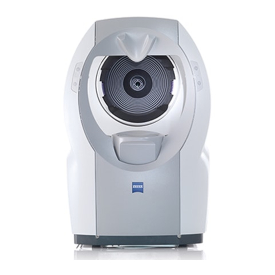
Page 20: Fig. 7 I.profiler ® Plus , View From The Patient Side
Description of the device 1 Device base with computer and electronics 2 Motorized chin rest 3 Two-button control of chin rest on both sides 4 Exit aperture of measuring optics 5 Forehead rest ® plus Fig. 7 i.Profiler , view from the patient side 000000-1520-928_GA_EN_021013... -
Page 21: Installation
Installation Installation WARNING - GENERAL HAZARDS The device may not be stored or operated in ambient conditions other than those prescribed (see Technical data on page 54). The device should be set up so that the power cable can be disconnected from the power supply quickly and easily without any tools. - Page 22 Installation CAUTION - DANGER FROM FALLING PARTS When selecting a suitable table, ensure that the combination of table and device is stable up to an angle of tilt of 10°. Furthermore, the table must be designed for 4 times the weight of the device configuration. If the table is on casters, these must have a locking device.
-
Page 23: Installation
Installation Installation CAUTION - PROPERTY DAMAGE For a change of location the device should always be lifted by two persons using the recessed handles (1, Fig. 8) on the underside. Do not use the display as a handle. As far as possible it should be transported on a moving support fitted with brakes. -
Page 24: Electrical Connection
Installation Electrical connection • Connect optional accessories, if available. • Connect power cable. 1 LAN connections with disconnection voltage of 4 kV (2) 2 USB ports (3) 3 VGA connector for monitor 4 RS232 serial interface 5 Fuse compartment 6 Power switch ON (I)/OFF (0) 7 Socket for power cable 8 In-built printer (paper prints) 9 USB port... -
Page 25: Calibration Touch Screen
Installation CAUTION - RISK OF OPERATING ERRORS Only software authorized by Carl Zeiss may be used on this device. The device may only be connected to networks which are protected from public networks (Internet) by firewalls conforming to the latest technical... -
Page 26: Integrating The I.profiler ® Plus Into An Existing Network Via Dhcp
Installation • Confirm your selection by clicking on OK. The Confirm Desktop Change dialog appears. • Confirm with OK. Alternatively you can proceed as follows: • Click on the symbol on the right side of the task bar. • Select Graphics Properties… from the menu bar. ®... -
Page 27: Integrating The I.profiler ® Plus Into An Existing Local Network
Installation ® plus Integrating the i.Profiler into an existing local network • Connect the i.Profiler ® plus to the practice network (LAN) using a network cable. • Switch the i.Profiler ® plus ® plus on. After the start, quit the i.Profiler software by pressing the Close Application button in the Shut Down window and switch to the Microsoft Windows desktop (administrator rights required). -
Page 28: Printer Installation For The I.profiler ® Plus
Installation ® plus Printer installation for the i.Profiler WARNING - RISK OF ELECTRIC SHOCK The printer must be set up outside the patient environment (1.5 m from the patient’s seat at the device) and plugged into a separate socket. The user should not simultaneously touch the patient and the printer. -
Page 29: Connecting The Printer To The I.profiler
Installation ® plus Connecting the printer to the i.Profiler directly (peer-to-peer) • Connect the network printer or printer server with the i.Profiler ® plus using a crossover cable or a standard cable with a crossover adapter. • Switch on the i.Profiler ®... -
Page 30: Connecting The Printer Via An Existing Network
Installation Connecting the printer via an existing network The administrator responsible for your local network must first set up a network printer or printer server in the network. The procedure for printer configuration is described in the user manual for the network printer or printer server. -
Page 31: Configuration Of A Network Memory Device
. These instructions specify the requirements and recommendations for the NAS device. Either a Carl Zeiss Vision NAS device or an NAS device from a preferred supplier that satisfies these requirements (generic NAS device) may be used. The NAS device may be plugged directly into the Ethernet connection of the ®... -
Page 32: Requirements Made On The Nas Device
Installation Requirements made on the NAS device The NAS device must have the following features to guarantee safety and ® plus acceptable performance in use of the i.Profiler • Support of 100BaseT or 1000BaseT Ethernet. For safety reasons a USB ®... -
Page 33: Installation Of The Nas Device
. A light at the front of the NAS device often indicates by a change of color that initialization has been completed. For more detailed instructions see the manufacturer's operating manual. Installation of the Carl Zeiss Meditec (CZM) NAS device • Switch the i.Profiler ® plus ® plus on. - Page 34 • Generate a local directory on the NAS device. • Generate a user account on the NAS device. It is recommended to use the user name "Zeiss" and the password "November171846". • If a Workgroup is available, it is recommended to name it "CZM".
- Page 35 Installation Connecting the NAS device via an existing network • With the i.Profiler ® plus and NAS device switched off connect the NAS device to the practice network (LAN) in which the i.Profiler ® plus is located. Detailed instructions on how to install the NAS device are provided in the manual accompanying the NAS device.
-
Page 36: Installation Of The Atlas Review Software Connection
To install the Atlas Review Software on a PC follow the user manual Atlas Corneal Topography System Review Software until chapter Connecting the Review Station to an ATLAS Instrument. Please contact Carl Zeiss Meditec, Inc. if you need installation support. Connecting the PC with the Atlas Review Software directly to ® plus the i.Profiler... - Page 37 Installation Installation of the Atlas Review Software connection • Double-click the program icon Initialize Atlas Review Mapping on the Windows desktop and select the network connector used (peer to peer connection) in the Initialize Atlas Review Station Connection dialog to connect the PC with the drive letter R:\.
-
Page 38: Connect Atlas Review Software Via An Existing Network With I.profiler ® Plus
Installation Connect Atlas Review Software via an existing network with ® plus i.Profiler ® plus Notes on integrating the i.Profiler into an existing network you will find ® plus in the section Integrate i.Profiler into an existing network via DHCP, page 24. - Page 39 Installation Connection of the ATLAS Review Station to a network server • Switch on the PC with the Atlas Review Software installation. • Open Windows Explorer. Enter the characters "\\" and then the IP address or the name of the storage medium in the Address field (e.g. network ®...
-
Page 40: Daily Use
• Use the power cable supplied with the device. If the device is mounted to an instrument table, it is powered through this table. If using a table not approved by Carl Zeiss Vision, the user is solely responsible for ensuring the electrical safety of the device. -
Page 41: Switching On
Daily use Switching on • To switch on the device, press the power switch (6, Fig. 9) followed by ® plus the Standby button (3, Fig. 6). The i.Profiler software is automatically launched and the Patient window will open. • After switching on, a function test of the measurement functions on the test eye pair must be performed pursuant to the instructions in the ®... -
Page 42: Operation
Operation Operation User's safety obligations CAUTION - RISK OF MEASURING ERRORS When operating radio devices or components for radio transmission, observe the distances recommended in section Electromagnetic compatibility, page 56 ff. ® plus Users should not rely solely on measurements made using the Profiler in making decisions regarding the adaptation and prescription of visual aids or therapeutic procedures, etc., but should rely on their own expertise and judgment. -
Page 43: Work Sequence
Operation Work sequence The following work sequence is recommended: • Explain the i.Profiler ® plus measurement procedure to the patient. • Open the patient database and enter the data of the patient to be measured if it does not already exist (Patient Database window). •... - Page 44 Operation ® plus Explaining the i.Profiler measurement procedure to the patient WARNING - GENERAL HAZARDS Persons who are not authorized to use the device (see chapter Specified purpose, page 7) may not be left unattended at or in the vicinity of the device.
- Page 45 Operation CAUTION - RISK OF MEASURING ERRORS The wearing of rigid or soft contact lenses may have an effect on the surface geometry of the cornea and thus the optical state of the eye. For topography and wavefront measurement of wearers of soft lenses a rest period of at least two weeks should thus be observed from the time the lens is removed to the time of measurement.
-
Page 46: Positioning The Patient For Measurements
Operation Positioning the patient for measurements • Renew the upper paper pad on the chin rest after each patient. • Ask the patient to position his/her chin on the motorized chin rest and forehead against the forehead rest. • Ensure that the patient's chin is on the front edge of the chin rest. •... -
Page 47: Shutting Down
If one of the following events should occur, switch the device off immediately at the power switch, disconnect the power cable, label the device clearly as being out of service and report the problem to Carl Zeiss Vision • Electric shocks •... - Page 48 Shutting down If the device is switched off at the standby button (3, Fig. 6) while it is in operation, the program will quit automatically before the device switches to standby mode. Wait until the blue light beside the standby switch goes off before switching off at the power switch (6, Fig.
-
Page 49: Maintenance And Care
Further maintenance procedures above and beyond those specified in this section (maintenance, safety inspections and repairs) may only be carried out by persons authorized by Carl Zeiss and solely according to the service instructions issued by Carl Zeiss. Fault remedy The following troubleshooting tables list possible problems encountered in ®... -
Page 50: Monitor Problems
Maintenance and care Monitor problems Fault/Problem Possible causes Remedy Display is black & white or Monitor problem Contact customer the colors are distorted. service. Cable problem Display colors change Cable problem Contact customer when monitor is moved. service. Problems with the internal printer Fault/Problem Possible causes Remedy... -
Page 51: Measurement Problems
Maintenance and care Measurement problems Fault/Problem Possible causes Remedy Centering phase The patient's eye is The chin rest is set too Correct the height of the misaligned upwards and high. chin rest. cannot be centered with the aid of the touchscreen (error message appears). - Page 52 Maintenance and care Fault/Problem Possible causes Remedy Focusing phase The instrument head does The patient's forehead is Ensure that the patient's not automatically focus not against the forehead forehead is firmly (error message appears). rest. against the forehead rest. The patient is pseudo Use manual focusing.
-
Page 53: Replacing The Fuses
Maintenance and care Replacing the fuses WARNING - RISK OF ELECTRIC SHOCK Disconnect the power cable from the power supply before replacing the fuse. The fuses are located in the fuse box (5, Fig. 9, page 22) to the right of the ®... -
Page 54: Maintenance
Maintenance and care Maintenance Replacing the print paper roll WARNING - RISK OF ELECTRIC SHOCK Disconnect the power cable from the power supply before replacing the printing paper. • Open the paper compartment at the right hand side of the device (8, Fig. - Page 55 Never clean the exit aperture of the measuring optics (4, Fig. 7, page 18). The exit aperture of the measuring optics is inspected for contamination at every scheduled safety inspection. It may only be cleaned by a Carl Zeiss Vision representative.
-
Page 56: Technical Data
Maintenance and care Technical data ® plus i.Profiler basic unit ® plus Model designation i.Profiler Dimensions (footprint) 420 mm x 310 mm Weight approx. 30 kg Power connection 100 V~ to 240 V~ Supply frequency 50 Hz to 60 Hz ≤ 200 VA Power consumption ≤... - Page 57 Maintenance and care Ambient conditions for intended use and on-site storage Operating temperature +10 °C to +40 °C Relative humidity 30 % to 85 % non-condensing Altitude up to 3000 m above sea level Note: We reserve the right to make changes to the design and package check list in accordance with technical advances.
-
Page 58: Electromagnetic Compatibility
Electromagnetic compatibility Electromagnetic compatibility Guidance and manufacturer's declaration - electromagnetic emissions ® plus The i.Profiler is intended for use in the electromagnetic environment specified below. The customer or the ® plus user of the i.Profiler should assure that the device is used in such an environment. Emissions test Compliance Electromagnetic environment - guidance... - Page 59 Electromagnetic compatibility Guidance and manufacturer’s declaration - electromagnetic immunity ® plus The i.Profiler is intended for use in the electromagnetic environment specified below. ® plus The customer or the user of the i.Profiler should assure that the device is used in such an environment. Immunity checks IEC 60601-1-2 test Compliance level...
- Page 60 Electromagnetic compatibility Guidance and manufacturer’s declaration - electromagnetic immunity ® plus The i.Profiler is intended for use in the electromagnetic environment specified below. ® plus The customer or the user of the i.Profiler should assure that the device is used in such an environment. Immunity test IEC 60601-1-2 Conformity level...
- Page 61 Electromagnetic compatibility Recommended separation distances between portable and mobile RF communications equipment and the ® plus i.Profiler ® plus The i.Profiler is intended for use in an electromagnetic environments in which related RF disturbances are ® plus controlled. The customer or the user of the i.Profiler can help prevent electromagnetic interference by maintaining a minimum distance between portable and mobile RF communications equipment (transmitters) ®...
-
Page 62: Abbreviations/Glossary
Abbreviations/Glossary Abbreviations/Glossary Deutsches Institut für Normung (German Standards Institute) European standard European Union Fig. Figure International Electrotechnical Commission Local area network Local network LOCS III Lens opacity classification system III Lens clouding classification system Network attached storage Network attached storage device RJ-45 Registered jack Standard plug-type connector for data lines... -
Page 63: Figures
Figures Figures ® plus Fig. 1 Type plate on the i.Profiler ..........10 Fig. 2 Measuring principle of the Hartmann-Shack sensor ....12 Fig. 3 Image of light spots on the camera chip (A) and image of the reconstructed wavefront map (B) over the total exit pupil. -
Page 64: Index
Index Index Abbreviations .................... 60 Accessories ....................5 Care ......................52 Classification of the device ................6 Components ..................... 17 Connection panel ..................22 Connections....................22 Controls ....................17 Data entry....................20 Description of the device................17 Disposal ...................... 9 Electromagnetic compatibility .............. - Page 65 Index Patient Explanation .................... 42 Positioning ..................... 44 Performance specifications ................ 12 Printer installation..................26 Recessed handles..................21 Service life ....................16 Shutting down ..................45 Software description.................. 40 Specified purpose ..................7 Symbols ....................... 4 Technical data ................... 54 Topography measurement .................
- Page 66 Carl Zeiss Vision GmbH 000000-1520-928_GA_EN_021013 ® plus Turnstrasse 27 i.Profiler 73430 Aalen Specifications subject to change Germany...
Need help?
Do you have a question about the i.Profiler plus and is the answer not in the manual?
Questions and answers