Advertisement
Quick Links
Advertisement
Chapters

Related Manuals for Zeiss ELYRA 7


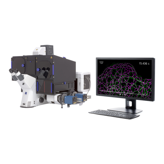
Summary of Contents for Zeiss ELYRA 7
- Page 1 March 2019 ZEN 3.0 SR (black edition)
- Page 2 Violations will entail an obligation to pay compensation. All rights reserved in the event of granting of patents or registration of a utility model. Issued by Carl Zeiss Microscopy GmbH Carl-Zeiss-Promenade 10 07745 Jena, Germany microscopy@zeiss.com www.zeiss.com/microscopy...
- Page 3 INTRODUCTION ELYRA 7 ZEISS How to make best use of the ELYRA 7 operating instructions: A few symbols in these operating instructions will help you to recognize the nature and purpose of information immediately: The WARNING symbol warns against hazards for the user that might arise when operating the laser.
- Page 4 INTRODUCTION ZEISS ELYRA 7 Contents System Operation In this section you will find the most important steps and procedures of the menu structure. The step-by-step description how to get an image will be shown by typical application examples including the WINDOWS graphic user environment.
-
Page 5: Table Of Contents
CHAPTER 1 - SYSTEM OPERATION ELYRA 7 Contents ZEISS CHAPTER 1 SYSTEM OPERATION CONTENTS Page PURPOSE ......................7 Software......................... 7 Convention for the Text in this Manual ............... 7 Backup ..........................8 Software Operation ....................... 8 HARDWARE ASPECTS ..................9 Principles of Superresolution Microscopy (ELYRA) ............ -
Page 6: Software And Hardware Options
CHAPTER 1 - SYSTEM OPERATION ZEISS Contents ELYRA 7 Main Toolbar ........................ 37 Status Bar ........................39 Left Tool Area ....................... 40 4.8.1 Tool Groups and Tools ..................... 42 4.8.2 Context Menu of the Left Tool Area ................. 43 Center Screen Area ....................... 44 4.9.1... - Page 7 CHAPTER 1 - SYSTEM OPERATION ELYRA 7 Contents ZEISS 5.2.11 Acquisition Parameter – Focus ..................99 5.2.12 Acquisition Parameter – Definite Focus ................101 5.2.13 Focus Devices and Strategies for Widefield Imaging Modes ..........111 5.2.14 Acquisition Parameter – Stage ..................112 5.2.15...
- Page 8 CHAPTER 1 - SYSTEM OPERATION ZEISS Contents ELYRA 7 5.3.15 Processing – Localization Microscopy ................191 5.3.16 Processing – Particle Tracking ..................199 5.3.17 Processing – Experimental PSF ..................201 5.3.18 Processing – SIM Tools ....................205 5.3.18.1 SIM – Fourier Transform ....................206 5.3.18.2 SIM –...
- Page 9 CHAPTER 1 - SYSTEM OPERATION ELYRA 7 Contents ZEISS CENTER SCREEN AREA / IMAGE CONTAINERS - DISPLAY AND IMAGE ANALYSIS ......................281 Structure and Functional Concept of the Center Screen Area and the Image Display Container ................... 281 6.1.1 General Structure ......................281 6.1.2...
- Page 10 CHAPTER 1 - SYSTEM OPERATION ZEISS Contents ELYRA 7 6.16 Unmixing View ......................350 6.16.1 Automatic Component Extraction .................. 353 6.17 FRET View ........................354 6.17.1 Tools in the FRET View Options Control Block for Acceptor Photobleaching ....356 6.17.2 Tools in the FRET View Options Control Block for Sensitized Emission ......
-
Page 11: Purpose
The installation of the software for the Laser Scanning Microscope and the basic settings of the equipment components are carried out by ZEISS service staff. This job includes the creation of a customized software configuration in line with the specific hardware components of the customer's microscope system. -
Page 12: Backup
The following user-generated files should be included in a backup procedure controlled and carried out on a regular basis by the user (keep directory structure): − Carl Zeiss Image files: *.czi − LSM Image files: *.lsm − Exported images: *.* (*.Tiff, *.LSM-Tiff, *.BMP, …) −... -
Page 13: Hardware Aspects
CHAPTER 1 - SYSTEM OPERATION ELYRA 7 Hardware Aspects ZEISS Hardware Aspects Principles of Superresolution Microscopy (ELYRA) A point object imaged by an objective lens will always be a blurred spot, the so called point spread function (PSF), due to the diffraction of light. - Page 14 CHAPTER 1 - SYSTEM OPERATION ZEISS Hardware Aspects ELYRA 7 The interference of the structured light with object structures requires that at least part of the light is coherent and leads to so called Moirè fringes whose pattern has a longer periodicity and hence a lower space frequency compared to the object (Fig.
-
Page 15: Principle Of Photo Activated Localization Microscopy (Smlm)
In Lattice SIM we have a 7 orders. Hence 13 (2 x 7 + 1) phase shifted images are minimally required. In ELYRA 7 15 phase images are used to have more information for reconstruction of the SIM image. Since the Lattice SIM pattern is symmetrical, no rotaion is necessary. - Page 16 CHAPTER 1 - SYSTEM OPERATION ZEISS Hardware Aspects ELYRA 7 Fig. 6 Principle of SMLM – Whereas in normal widefield images the PSF of closely juxtaposed point sources can overlap heavily (upper panel) their sequential illumination and plotting of their center of mass will...
-
Page 17: Optical Diagram Of Elyra (Schematic)
Optical Diagram of ELYRA (Schematic) Fig. 7 Optical path, schematic (ELYRA 7) The diagram is a schematic representation of the ELYRA system (Fig. 7). Laser light is focused into the back focal plane of the objective to obtain widefield illumination in the specimen. - Page 18 Attachment sites for illumination modules and cameras The ELYRA 7 module is always attached at the rear port (RP) of the Axio Observer 7 SR. An LSM module is always mounted to the left side port (SPl) of the stand. The Duolink will always be mounted, if present, on the right side port (SPr).
-
Page 19: Performance And Features Of Elyra
Performance and Features of ELYRA Optical and mechanical aspects The ELYRA 7 family members have only one illumination / detection unit, the ELYRA 7 module, attached to the rear port of the microscope. The ELYRA module is designed for performing single molecule localization microscopy (SMLM) and/or Lattice structured illumination microscopy (Lattice SIM) SMLM. -
Page 20: Microscope Equipment Of Elyra Systems
ELYRA 7 Microscope Equipment of ELYRA Systems The ELYRA 7 systems are equipped with the inverted Axio Observer 7 SR microscope with a modified rear port for the attachment of ELYRA illumination modules. Only the differences from the delivered operating manual "Axio Observer" will be explained here. - Page 21 CHAPTER 1 - SYSTEM OPERATION ELYRA 7 Hardware Aspects ZEISS Transmitted-light illumination − The illuminator support contains a security circuit which activates a shutter preventing laser light from reaching the stand when the support is moved to the back. A complementary shutter built in the stand prevents laser light from reaching the eyepieces during the scanning mode.
-
Page 22: Computer Hardware And Software
ELYRA 7 Computer Hardware and Software ELYRA 7 is controlled via a standard high-end Pentium Intel Xeon PC. Linking to the electronic control system is made via Gigabit Ethernet interface. The PC comes with the WINDOWS operating system. The instrument is fully motorized, permitting fast change-over between methods as well as automatic operation. -
Page 23: Startup And Shutdown Of The System
Startup and Shutdown of the System Startup of the System ELYRA 7 systems are equipped with three Multipoint connectors that are plugged via different sockets of the Electronic Control Unit. The systems are equipped with a Main power switch on the Electronic control Unit (ECU). There is a further remote switch labeled Components that is connected to the ECU. -
Page 24: Starting Zen
(Fig. 8). It displays the ZEN symbol in the upper part, the designation of the current ZEN software version (lower left) and the Zeiss icon (lower right). − Once the program is loaded the Login ZEN dialog Fig. 8 Starting the ZEN software –... - Page 25 CHAPTER 1 - SYSTEM OPERATION ELYRA 7 Startup and Shutdown of the System ZEISS − Start System for system control, data / image acquisition / recording and analysis. The whole microscope system will be initialized. The progress of the boot process will be displayed by the blue time tab.
- Page 26 ZEISS Startup and Shutdown of the System ELYRA 7 − If Recent… is pressed the last couple of databases that were in use will be displayed (Fig. 14). Click on the one you want to select. By pressing the Choose… button Windows Explorer will open. Search for the folder file the database is stored and and open it.
-
Page 27: Shutdown Procedure
CHAPTER 1 - SYSTEM OPERATION ELYRA 7 Startup and Shutdown of the System ZEISS Shutdown Procedure Never shut down the computer by its main switch while the ZEN software is still active, or else you will lose the currently set operating parameters and the images just scanned. -
Page 28: Switching System Power Off
CHAPTER 1 - SYSTEM OPERATION ZEISS Startup and Shutdown of the System ELYRA 7 If the box is not ticked, the Laser Off dialog box will appear that allows one to check on the listed lasers (Fig. 16). By the Power drop down menu, if available, the laser can be left On, put in Standby or turned Off. -
Page 29: Introduction To The Software Application Layout
CHAPTER 1 - SYSTEM OPERATION ELYRA 7 Introduction to the Software Application Layout ZEISS Introduction to the Software Application Layout Overview on the Screen Layout Fig. 17 ZEN Main Application window after Startup with empty image container Fig. 18 ZEN Main Application window after Startup with several images loaded... -
Page 30: Introduction To Zen
Introduction to the Software Application Layout ELYRA 7 Introduction to ZEN ZEN - Efficient Navigation - is the new software for the LSM/ELYRA Family from ZEISS. With the launch of this software in 2007 ZEISS sets new standards in application-friendly software for Laser Scanning Microscopy. - Page 31 CHAPTER 1 - SYSTEM OPERATION ELYRA 7 Introduction to the Software Application Layout ZEISS Fig. 19 Show all mode The Show all concept ensures that tool panels are never more complex than needed. In the basic mode of the tools Show all is deactivated and the tools show only the most relevant functions, covering approximately 80% of the application.
- Page 32 CHAPTER 1 - SYSTEM OPERATION ZEISS Introduction to the Software Application Layout ELYRA 7 Fig. 20 ZEN window Layout configuration More features of ZEN include: − The user can add more columns to the Left Tool Area or detach individual tools to position them anywhere on the monitor.
-
Page 33: Function Elements
CHAPTER 1 - SYSTEM OPERATION ELYRA 7 Introduction to the Software Application Layout ZEISS Function Elements Function element Description / Explanation Tool group Tool (closed) or tool window (opened) Panel (e.g.: Averaging panel) − Field with a subset of tools of a tool window List box or selection box −... - Page 34 CHAPTER 1 - SYSTEM OPERATION ZEISS Introduction to the Software Application Layout ELYRA 7 Slider with input ("spin") box and arrows − Setting of numbers in the relevant input box by moving the slider or clicking on the arrow buttons or clicking on the slider and moving via the arrow keys of the keyboard.
-
Page 35: Application Bar
CHAPTER 1 - SYSTEM OPERATION ELYRA 7 Introduction to the Software Application Layout ZEISS Application Bar The application bar includes the following control elements of the ZEN software application window: Starts the online help Minimizes the application window Maximizes over 2 screens... - Page 36 CHAPTER 1 - SYSTEM OPERATION ZEISS Introduction to the Software Application Layout ELYRA 7 Menu overview 000000-2262-999 03/2019 V_02...
-
Page 37: File
CHAPTER 1 - SYSTEM OPERATION ELYRA 7 Introduction to the Software Application Layout ZEISS For detailed information about the image acquisition functions see section Acquisition Tab. The functionalities of the Macro menu are described in CHAPTER 2: MACROS AND VISUAL BASIC. -
Page 38: Maintain
CHAPTER 1 - SYSTEM OPERATION ZEISS Introduction to the Software Application Layout ELYRA 7 4.5.2 Maintain The Maintain menu from the Menu bar contains additional modules to check and guarantee the interference-free operation of all the software and hardware components of the systems. In the Menu bar, click Maintain. -
Page 39: Remote Access Settings
ELYRA system. Enable the Remote Access and define a user name and password for the access which then must be used to login form the iPad. Download the "ZEISS Remote" App from the App-Store and install it on your iPad. -
Page 40: Help - About
CHAPTER 1 - SYSTEM OPERATION ZEISS Introduction to the Software Application Layout ELYRA 7 4.5.3 Help – About The About window can be accessed via the Help item in the menu bar clicking About opens the following dialog: Fig. 27... -
Page 41: Main Toolbar
CHAPTER 1 - SYSTEM OPERATION ELYRA 7 Introduction to the Software Application Layout ZEISS Main Toolbar Fig. 28 Main toolbar, left side Fig. 29 Main toolbar, right side Workspace Configuration This function allows loading, saving or deleting a workspace configuration. These workspace... - Page 42 CHAPTER 1 - SYSTEM OPERATION ZEISS Introduction to the Software Application Layout ELYRA 7 • To load a workspace configuration, click on the button. The following list box will appear: Selecting on of the list entries will load the respective configuration.
-
Page 43: Status Bar
CHAPTER 1 - SYSTEM OPERATION ELYRA 7 Introduction to the Software Application Layout ZEISS Status Bar Fig. 30 Status bar Progress bar Shows an overview of all running processes. If only one process is running the details of this one are shown. -
Page 44: Left Tool Area
CHAPTER 1 - SYSTEM OPERATION ZEISS Introduction to the Software Application Layout ELYRA 7 Left Tool Area Main Tool tabs Switches between the Locate, Acquisition, Processing and Maintain main tools to operate the included tool Action buttons Action buttons are only available for the Acquisition Main tool to control the image acquisition process. - Page 49 CHAPTER 1 - SYSTEM OPERATION ELYRA 7 Introduction to the Software Application Layout ZEISS Image tabs For each opened image one image tab is shown in the header Fig. 37 Image tabs of the actual container. Three modes can be selected using the context menu of the Center Screen Area (see also section Context Menu of the Center Screen Area).
-
Page 50: Context Menu Of The Center Screen Area
CHAPTER 1 - SYSTEM OPERATION ZEISS Introduction to the Software Application Layout ELYRA 7 Arrow down button Clicking on this button shows a list with all opened images for fast image selection. Using the drag and drop function, one or several images can be moved into another opened container. -
Page 51: Right Tool Area
CHAPTER 1 - SYSTEM OPERATION ELYRA 7 Introduction to the Software Application Layout ZEISS 4.10 Right Tool Area The Right Tool Area is used for displaying and handling the opened images, e.g. save or close. The view of this area can be varied individually, e.g. - Page 52 CHAPTER 1 - SYSTEM OPERATION ZEISS Introduction to the Software Application Layout ELYRA 7 Big View button Shows images with the textual characters and a big image preview. Save Status icon This icon appears in the image that is not saved yet.
-
Page 53: Left Tool Area And Hardware Control Tools
CHAPTER 1 - SYSTEM OPERATION ELYRA 7 Left Tool Area and Hardware Control Tools ZEISS Left Tool Area and Hardware Control Tools The Left Tool Area contains all tools for system operation, image acquisition, image processing and maintenance. The major functions are organized in the four Main tool tabs (Fig. -
Page 54: Locate Tab
CHAPTER 1 - SYSTEM OPERATION ZEISS Left Tool Area and Hardware Control Tools ELYRA 7 Locate Tab Locate contains all functions of the microscope for visual inspection of the sample through the eyepieces (Fig. 43). You can open the shutters for Transmitted Light Fig. - Page 55 CHAPTER 1 - SYSTEM OPERATION ELYRA 7 Left Tool Area and Hardware Control Tools ZEISS To delete a configuration press the Delete button ). This opens the Delete Configuration panel (Fig. 45). Select ocular configuration from Configurations list by highlighting it or search for it by typing its name in the Search field.
-
Page 56: Microscope Control Tool For Axio Observer
ZEISS Left Tool Area and Hardware Control Tools ELYRA 7 These microscope functions can also be operated directly on the microscope stand via assigned buttons or through the touch screen, if available. In that case, any changes are recorded by the software and displayed in the relevant windows / panels. - Page 57 CHAPTER 1 - SYSTEM OPERATION ELYRA 7 Left Tool Area and Hardware Control Tools ZEISS HAL transmitted light Open/Close shutter button: The shutter for transmitted light from the HAL lamp is switched on and off by repeated pressing (Fig. 51).
- Page 58 CHAPTER 1 - SYSTEM OPERATION ZEISS Left Tool Area and Hardware Control Tools ELYRA 7 Focus button: If the focus button is pressed, the Focus control panel will appear (Fig. 54). The Z-Position display box shows the current z-position. The number can be edited by typing or using the arrowheads.
- Page 59 CHAPTER 1 - SYSTEM OPERATION ELYRA 7 Left Tool Area and Hardware Control Tools ZEISS Tube Lens button: The tube lens can be selected via a graphical pop- up menu (Fig. 57). Lens 1x is used for ocular observation and widefield imaging using an arc lamp, Lens LSM is used for laser scanning imaging and Lens 1.6x is used for widefield imaging using...
- Page 60 CHAPTER 1 - SYSTEM OPERATION ZEISS Left Tool Area and Hardware Control Tools ELYRA 7 Visual inspection via binoculars • In the main toolbar, activate the Locate tab. • Choose the Microscope Control tool. For transmitted-light observation (Bright-field) • Switch the HAL lamp on by the HAL On/Off button and adjust the light intensity.
- Page 61 CHAPTER 1 - SYSTEM OPERATION ELYRA 7 Left Tool Area and Hardware Control Tools ZEISS Conventional setting of the microscope Axio Observer The Recording of microscope settings works as described for the microscope Axio Imager. For the conventional setting of the Axio Observer, proceed as follows: •...
-
Page 62: Incubation Tool
CHAPTER 1 - SYSTEM OPERATION ZEISS Left Tool Area and Hardware Control Tools ELYRA 7 5.1.2 Incubation Tool To have access to incubator functions to define the atmosphere and temperature, you have to expand the Incubation tool by pressing the arrow in the Incubation tool (Fig. 61) You will have access dependent on the attached equipment to −... -
Page 63: Acquisition Tab
CHAPTER 1 - SYSTEM OPERATION ELYRA 7 Left Tool Area and Hardware Control Tools ZEISS Acquisition Tab • Acquisition contains all functions of the microscope that are needed to set up and control widefield imaging by bright field or fluorescence, designated in this manual as... -
Page 64: Configuration Functions
CHAPTER 1 - SYSTEM OPERATION ZEISS Left Tool Area and Hardware Control Tools ELYRA 7 5.2.1 Configuration Functions You can load predefined acquisition parameters from the Experiment Manager field (Fig. 63) by Fig. 63 Experiment Manager field with loaded pressing the Load button (... - Page 65 CHAPTER 1 - SYSTEM OPERATION ELYRA 7 Left Tool Area and Hardware Control Tools ZEISS Select the acquisition configuration from the Parameters list by highlighting it or search for it by typing its name in the Search field. An Info menu pops up (Fig.
-
Page 66: Action Buttons
CHAPTER 1 - SYSTEM OPERATION ZEISS Left Tool Area and Hardware Control Tools ELYRA 7 5.2.2 Action Buttons Action buttons provide control for how the image is acquired (Fig. 68). Fig. 68 Action buttons They have the following functions, regardless of the imaging mode: AF Find Focus triggers a frame z-Scan. - Page 67 CHAPTER 1 - SYSTEM OPERATION ELYRA 7 Left Tool Area and Hardware Control Tools ZEISS Continuous produce images from all active channels and tracks, thereby ignoring the settings for multidimensional acquisition, but taking into account the selected imaging mode. The last scanned frame will stay in the image window.
-
Page 68: Multidimensional Acquisition Settings
CHAPTER 1 - SYSTEM OPERATION ZEISS Left Tool Area and Hardware Control Tools ELYRA 7 5.2.3 Multidimensional Acquisition Settings In the Multidimensional acquisition field (Fig. 74), the multidimensionality can be defined by checking the corresponding boxes. Fig. 74 Multidimensional input field – Z-Stack (with 10 slices), Time series (with 10 images) and... - Page 69 CHAPTER 1 - SYSTEM OPERATION ELYRA 7 Left Tool Area and Hardware Control Tools ZEISS Fig. 76 Multidimensional Acquisition Tool group Note that not all functions are available for all imaging modes. Only those functions that are available can be activated; non-available functions are greyed out and inactive.
-
Page 70: Setup Manager - Laser
CHAPTER 1 - SYSTEM OPERATION ZEISS Left Tool Area and Hardware Control Tools ELYRA 7 5.2.4 Setup Manager – Laser Open (and close) the Laser tool (Fig. 79) by clicking the Laser tab in the Setup Manager tool group. Lasers are listed with their Laser name, their Laser lines (nm) and their Power state. -
Page 71: Setup Manager - Imaging Setup
CHAPTER 1 - SYSTEM OPERATION ELYRA 7 Left Tool Area and Hardware Control Tools ZEISS 5.2.5 Setup Manager – Imaging Setup Imaging Setup tool (Fig. 81) allows new / existing beam path configurations and track definitions to be created / edited and saved for the different imaging modes. -
Page 72: Sequential Laser Switching
CHAPTER 1 - SYSTEM OPERATION ZEISS Left Tool Area and Hardware Control Tools ELYRA 7 5.2.5.1 Sequential Laser Switching Whenever at least two tracks are active, Sequential laser switching becomes available from the Switch track every drop down menu of the Imaging Setup tab (Fig. - Page 73 CHAPTER 1 - SYSTEM OPERATION ELYRA 7 Left Tool Area and Hardware Control Tools ZEISS Please note that the number of cycles in Time Series must be an integer multiple of the Sequence Size. If changing the number of Sequence Size in a way that...
- Page 74 CHAPTER 1 - SYSTEM OPERATION ZEISS Left Tool Area and Hardware Control Tools ELYRA 7 Fig. 87 Image container in "Split" view for two sequential tracks If Online Processing was active, SMLM and SWF images will be available for both channels. All Processing and Display options will be available for the SMLM image including Drift correction and Grouping.
-
Page 75: Beam Path Configuration
In the Beam path configuration field the beam path can be selected (Fig. 88, Fig. 89 and Fig. 90). It depends on the ELYRA 7 type, the presence of Duolink and Imaging mode selected, what components are accessible. Some components are common to all imaging modes, whereas others will be specific. - Page 76 CHAPTER 1 - SYSTEM OPERATION ZEISS Left Tool Area and Hardware Control Tools ELYRA 7 The WF and Laser WF light path tools have different appearances for different systems. The camera selection tabs are only available for ELYRA type LS systems. ELYRA types L,...
-
Page 77: Camera Selection
Andor SMLM) and an sCMOS pco.edge CLHS at the baseport (BP) (TV2: sCMOS pco SIM). For ELYRA 7 type LS (1 EMCCD & 1 sCMOS) the camera can be activated by pressing the respective TV1/2: EM CCD Andor SMLM / sCMOS pco SIM... - Page 78 ELYRA 7 For ELYRA 7 types L (1 or 2 EMCCDs), S (1 or 2 sCMOS) and eLS (1 or 2 sCMOS), if one camera is present, it will be automatically active for a track. In case of two cameras check boxes are available that when ticked will activate the respective camera.
-
Page 79: Tube Lens Selection
CHAPTER 1 - SYSTEM OPERATION ELYRA 7 Left Tool Area and Hardware Control Tools ZEISS 5.2.5.4 Tube Lens Selection The correct tube lens is automatically chosen for the corresponding imaging mode, but can be altered sub sequentially. The tube lens can be selected via a graphical pop- up menu of the Tube lens button (Fig. -
Page 80: Hal Control
CHAPTER 1 - SYSTEM OPERATION ZEISS Left Tool Area and Hardware Control Tools ELYRA 7 5.2.5.7 HAL Control When the HAL On/Off button (available for WF, SIM Apotome and Lattice SIM and Laser WF imaging modes) for transmitted light of the halogen lamp is pressed, the control panel for the light settings is displayed (Fig. -
Page 81: Power Density Control
CHAPTER 1 - SYSTEM OPERATION ELYRA 7 Left Tool Area and Hardware Control Tools ZEISS 5.2.5.10 Power Density Control Press the Power density button (available only for SIM Apotome, Lattice SIM and Laser WF imaging modes) to open the selection panel for the requested telescope optics, which define the area the light is concentrated to (Fig. -
Page 82: Collimator Setting
CHAPTER 1 - SYSTEM OPERATION ZEISS Left Tool Area and Hardware Control Tools ELYRA 7 5.2.5.12 Collimator Setting The Collimator setting is specific for the Laser WF imaging mode. • Press the Collimator button to open the Fig. 101 Collimator settings panel Collimator settings panel (Fig. - Page 83 CHAPTER 1 - SYSTEM OPERATION ELYRA 7 Left Tool Area and Hardware Control Tools ZEISS You can exced the boundaries of the slider only when going to one of its end and pressing Save TIRF angle, as than the current poisition will be the center position. Continue until you have reached the desired angle.
- Page 84 CHAPTER 1 - SYSTEM OPERATION ZEISS Left Tool Area and Hardware Control Tools ELYRA 7 HILO mode: settled beads and out-of-focus beads become brightest (Fig. 106/B). Haze is reduced further. Brightness of settled and floating beads stay approximately the same, but out-of-focus haze becomes fainter as one approaches TIRF.
-
Page 85: 3D-Palm Slider
CHAPTER 1 - SYSTEM OPERATION ELYRA 7 Left Tool Area and Hardware Control Tools ZEISS 5.2.5.14 3D-PALM Slider In order to place the 3D-PALM slider in the back aperture of the objective for the experiment, press the 3D button (Fig. 108). -
Page 86: Acquisition Parameter - Experiment Designer
CHAPTER 1 - SYSTEM OPERATION ZEISS Left Tool Area and Hardware Control Tools ELYRA 7 5.2.6 Acquisition Parameter – Experiment Designer Experiment Designer combines different multi- dimensional acquisition parameters with each parameter setting assigned to one imaging block in one total experiment described as Multi Block Experiment. - Page 87 CHAPTER 1 - SYSTEM OPERATION ELYRA 7 Left Tool Area and Hardware Control Tools ZEISS New Blocks are added using the Create drop down list: A Acquisition Block is used for image acquisition which is performed according to the acquisition −...
- Page 88 CHAPTER 1 - SYSTEM OPERATION ZEISS Left Tool Area and Hardware Control Tools ELYRA 7 Pay attention to the following guidelines for the Experiment Designer Each Block generates a separate image file. Loops going back to a Block will add the newly −...
-
Page 89: Acquisition Parameter - Acquisition Mode
CHAPTER 1 - SYSTEM OPERATION ELYRA 7 Left Tool Area and Hardware Control Tools ZEISS 5.2.7 Acquisition Parameter – Acquisition Mode Acquisition Mode tool window, parameters for the acquisition can be set (Fig. 111,). The user interface is adapted depending on the chosen Imaging mode in the Imaging Setup tool. -
Page 90: Format And Trigger Selection
Fig. 115 Noise Filter drop down menu – the options to select standard binning (512 x appearance for ELYRA 7 512 standard), 2 x binning (256 x 256 binned 2x2) or 4 x binning (128 x 128 4x4). All cameras are run in exclusively in triggered mode, fre run is not available. -
Page 91: Acquisition Parameter - Incubation
CHAPTER 1 - SYSTEM OPERATION ELYRA 7 Left Tool Area and Hardware Control Tools ZEISS 5.2.7.3 Averaging and Color Depth Selection You can select the number of image frames you want to average from the Averaging Number drop down menu (Fig. 116). -
Page 92: Acquisition Parameter - Online Processing Options
CHAPTER 1 - SYSTEM OPERATION ZEISS Left Tool Area and Hardware Control Tools ELYRA 7 5.2.9 Acquisition Parameter – Online Processing Options The Online Processing Options tool is only available in the Laser WF imaging mode and allows to online process SMLM data, control the... -
Page 93: Control Activation Power
CHAPTER 1 - SYSTEM OPERATION ELYRA 7 Left Tool Area and Hardware Control Tools ZEISS 5.2.9.2 Control Activation Power Tick the Control activation power check box to have access to change the activation power during the experiment (Fig. 122). The check box is only available if the Online Processing SMLM check box is ticked. -
Page 94: Acquisition Parameter - Channels
CHAPTER 1 - SYSTEM OPERATION ZEISS Left Tool Area and Hardware Control Tools ELYRA 7 5.2.10 Acquisition Parameter – Channels In the Channels tool window the following options are available: − Switching, activating, deactivating and naming/saving of tracks − Defining laser and laser power (SIM Apotome, Lattice SIM, Laser WF) −... - Page 95 CHAPTER 1 - SYSTEM OPERATION ELYRA 7 Left Tool Area and Hardware Control Tools ZEISS Fig. 125 Channels tool – Appearance for the Laser WF imaging mode of ELYRA types S & eLS systems 03/2019 V_02 000000-2262-999...
-
Page 96: Defining Channels And Tracks
CHAPTER 1 - SYSTEM OPERATION ZEISS Left Tool Area and Hardware Control Tools ELYRA 7 5.2.10.1 Defining Channels and Tracks The Channels tool lists all tracks in the Track Selection display area that have been defined in the Imaging Setup tool. - Page 97 CHAPTER 1 - SYSTEM OPERATION ELYRA 7 Left Tool Area and Hardware Control Tools ZEISS The color of a track can be set or changed selecting a LUT from the Look Up Table (LUT) drop down menu (Fig. 128). The scroll bar allows access to all predefined colors.
- Page 98 CHAPTER 1 - SYSTEM OPERATION ZEISS Left Tool Area and Hardware Control Tools ELYRA 7 All saved track configurations will be listed in the Load Track Configuration panel (Fig. 131). Select the appropriate one by highlighting it in the Recent section, which lists the recently used track...
- Page 99 CHAPTER 1 - SYSTEM OPERATION ELYRA 7 Left Tool Area and Hardware Control Tools ZEISS The Info window pops up (Fig. 133). Press Yes to delete the configuration, No to keep the configuration. To save a configuration press the Save button (symbolized by the disc icon).
-
Page 100: Ratio Channels
CHAPTER 1 - SYSTEM OPERATION ZEISS Left Tool Area and Hardware Control Tools ELYRA 7 5.2.10.2 Ratio Channels The parameters for ratio metric imaging can be set when a ratio channel is selected. • Click on the button of a ratio channel (e.g. -
Page 101: Track Control
Fig. 140). Fig. 138 Channel tool – track control; appearance for the WF imaging mode of ELYRA 7 Types S & eLS Fig. 139 Channel tool – track control; appearance for the Lattice SIM imaging mode of ELYRA 7 types S &... - Page 102 CHAPTER 1 - SYSTEM OPERATION ZEISS Left Tool Area and Hardware Control Tools ELYRA 7 If in the Laser WF imaging mode at least one laser is selected, the Laser Trigger expansion field becomes available (see Fig. 141). When expanding the box, all active lasers will be displayed with their Trigger drop down menus.
-
Page 103: Display Options
CHAPTER 1 - SYSTEM OPERATION ELYRA 7 Left Tool Area and Hardware Control Tools ZEISS 5.2.10.4 Display Options You can set display options by opening the Display expansion field (see Fig. 143). Fig. 143 Display expansion field If the Auto copy from last acquired box is checked, the settings from the last acquired image will be taken. - Page 104 CHAPTER 1 - SYSTEM OPERATION ZEISS Left Tool Area and Hardware Control Tools ELYRA 7 Use of an optional high resolution focusing device (Piezo objective focus or Z-Piezo stage insert) The Piezo Position is indicated as a numerical value. This value and with it the focus position can be changed.
-
Page 105: Acquisition Parameter - Definite Focus
CHAPTER 1 - SYSTEM OPERATION ELYRA 7 Left Tool Area and Hardware Control Tools ZEISS 5.2.12 Acquisition Parameter – Definite Focus The Definite Focus tool is available in the Acquisition Parameter tool group if a Definite Focus (DF) device is physically attached to the system (Fig. - Page 106 CHAPTER 1 - SYSTEM OPERATION ZEISS Left Tool Area and Hardware Control Tools ELYRA 7 Action buttons Action buttons are used to execute reflex finding and focus stabilization by the Definite Focus device. The last used Action button will be indicated by a blue rim.
- Page 107 CHAPTER 1 - SYSTEM OPERATION ELYRA 7 Left Tool Area and Hardware Control Tools ZEISS If the projected pattern is detectable but too weak, or the signal peak is not completely captured within the range of the Definite Focus the Status: line will Fig.
- Page 108 CHAPTER 1 - SYSTEM OPERATION ZEISS Left Tool Area and Hardware Control Tools ELYRA 7 Slightly focus up and down using the stand’s Z-drive until your sample is in focus. Read the actual Z-position (offset between definite Focus and sample focus) in the Z-Position input box...
- Page 109 CHAPTER 1 - SYSTEM OPERATION ELYRA 7 Left Tool Area and Hardware Control Tools ZEISS Periodic When pressing the Periodic button, the system will periodically stabilize at the pre-set focal position. If 0 is entered in the Interval input window, stabilization will be continuous.
- Page 110 CHAPTER 1 - SYSTEM OPERATION ZEISS Left Tool Area and Hardware Control Tools ELYRA 7 Recall Focus When pressing the Recall Focus button, the system will for one time stabilize at the pre-set focal position (Fig. 159). During stabilization the Status: line will display in green a blinking message - Determine position -, if the process takes more than 1 sec.
- Page 111 CHAPTER 1 - SYSTEM OPERATION ELYRA 7 Left Tool Area and Hardware Control Tools ZEISS Z-Piezo control If the Use Z Piezo check box is inactive the Definite Focus will execute stabilization via the microscope stand’s Z-Drive. If the box is checked, the Definite...
- Page 112 ZEISS Left Tool Area and Hardware Control Tools ELYRA 7 In other words, whenever the Z-Piezo is involved during Periodic stabilization, either as the control element for the Definite Focus or as the device to alter the focus, the Definite Focus will regulate back to the pre-set focal position.
- Page 113 CHAPTER 1 - SYSTEM OPERATION ELYRA 7 Left Tool Area and Hardware Control Tools ZEISS Fig. 166 Warning information at ZEN Software startup if the system detects differences in the ZEN and Firmware listed objectives Info on Status The Status: line indicates the current status of the Definite focus.
- Page 114 CHAPTER 1 - SYSTEM OPERATION ZEISS Left Tool Area and Hardware Control Tools ELYRA 7 The Definite Focus tool during synchronous stabilization Whenever the Definite Focus is selected from the Autofocus Mode drop down menu of the Focus Device and Strategy tool (Fig. 168) as the focus strategy, this setting will overrule the settings made Fig.
-
Page 115: Focus Devices And Strategies For Widefield Imaging Modes
CHAPTER 1 - SYSTEM OPERATION ELYRA 7 Left Tool Area and Hardware Control Tools ZEISS After the end of the Experiment Periodic stabilization remains switched off. An active Find Surface becomes deactivated by pressing both, Continuous or Start Experiment and remains inactive after the scan finished. -
Page 116: Acquisition Parameter - Stage
CHAPTER 1 - SYSTEM OPERATION ZEISS Left Tool Area and Hardware Control Tools ELYRA 7 5.2.14 Acquisition Parameter – Stage The following software description applies to systems which are equipped with a motorized scanning stage. If the Stage tool window is expanded the Stage control tool becomes available (Fig. -
Page 117: Acquisition Parameter - Shuttle And Find
CHAPTER 1 - SYSTEM OPERATION ELYRA 7 Left Tool Area and Hardware Control Tools ZEISS 5.2.15 Acquisition Parameter – Shuttle and Find Shuttle and Find allows calibration and imaging of sample positions in laser wide field (laser WF) and SIM mode for reproducible repositioning after transfer to scanning electron microscopes (SEM). - Page 118 CHAPTER 1 - SYSTEM OPERATION ZEISS Left Tool Area and Hardware Control Tools ELYRA 7 • Go on with this procedure for marker two and three. Use coordinates for calculating the distances between the markers. Mounting of cover glasses or TEM grids •...
- Page 119 CHAPTER 1 - SYSTEM OPERATION ELYRA 7 Left Tool Area and Hardware Control Tools ZEISS Inserting a sample holder (various mounting frames are possible) • Insert the sample holder into the mounting frame (Fig. 178/3) of the microscope stage in the following way: −...
- Page 120 CHAPTER 1 - SYSTEM OPERATION ZEISS Left Tool Area and Hardware Control Tools ELYRA 7 Calibration The calibration markers consist of one small and a large L-shape marker. The bigger marker is used for coarse orientation, whereas the smaller marker is used for the calibration.
- Page 121 CHAPTER 1 - SYSTEM OPERATION ELYRA 7 Left Tool Area and Hardware Control Tools ZEISS Marker Color: White – Black – Automatic: Select the color of the markers (as it appears in the image window) or leave it to automatic.
- Page 122 CHAPTER 1 - SYSTEM OPERATION ZEISS Left Tool Area and Hardware Control Tools ELYRA 7 • If the stage is moving in the wrong direction, invert the direction by clicking on X Invert or Y Invert in the Sample Holder Calibration field Fig.
- Page 123 CHAPTER 1 - SYSTEM OPERATION ELYRA 7 Left Tool Area and Hardware Control Tools ZEISS Image acquisition and saving • Acquire images of your sample as you are used • For saving (Fig. 184) the images together with coordinates and defined regions of interest or points of interest use the .czi file format.
-
Page 124: Acquisition Parameter - Regions
CHAPTER 1 - SYSTEM OPERATION ZEISS Left Tool Area and Hardware Control Tools ELYRA 7 5.2.16 Acquisition Parameter – Regions The Regions tool tab is only available, if the Regions checkbox is ticked in the Multidimensional acquisition field. If the tool bar is expanded, the Regions tool becomes available (Fig. - Page 125 CHAPTER 1 - SYSTEM OPERATION ELYRA 7 Left Tool Area and Hardware Control Tools ZEISS The following tools are available in the Tool selection field: Selects an existing region in the image. The outline of the region is marked with small rectangles to show it is active.
- Page 126 CHAPTER 1 - SYSTEM OPERATION ZEISS Left Tool Area and Hardware Control Tools ELYRA 7 When highlighting a ROI in the list, the numerical parameters for Center X, Center Y, Width and Height in pixels will be shown in Region feature field.
- Page 127 CHAPTER 1 - SYSTEM OPERATION ELYRA 7 Left Tool Area and Hardware Control Tools ZEISS For widefield modes (WF, SIM Apotome, Lattice SIM, TIRF) the Bleach function is not available and will be ignored. The numbers of the different regions will be shown in the image if the check box next to Show numbers is checked.
-
Page 128: Multidimensional Acquisition - Z-Stack
CHAPTER 1 - SYSTEM OPERATION ZEISS Left Tool Area and Hardware Control Tools ELYRA 7 5.2.17 Multidimensional Acquisition – Z-Stack The Z-Stack tool tab is only available, if the Z-Stack checkbox is ticked in the Multidimensional acquisition field. If the tool bar is expanded, the Z-Stack tool becomes available (Fig. 193, Fig. 194, Fig. -
Page 129: Performing A Z-Stack Using First/Last Mode
CHAPTER 1 - SYSTEM OPERATION ELYRA 7 Left Tool Area and Hardware Control Tools ZEISS 5.2.17.1 Performing a Z-Stack Using First/Last Mode Press the First/Last mode button to open the First/Last definition panel. Press the Continuous action button and focus onto the specimen. - Page 130 CHAPTER 1 - SYSTEM OPERATION ZEISS Left Tool Area and Hardware Control Tools ELYRA 7 The rationale behind this is that SIM acquisition needs the accuracy of a Z-Piezo stage insert for taking Z- Stacks. The Fast Z Line checkbox is only available in Line Scan Mode to be selected in the Acquisition Mode tool).
-
Page 131: Performing A Z-Stack Using Center Mode
CHAPTER 1 - SYSTEM OPERATION ELYRA 7 Left Tool Area and Hardware Control Tools ZEISS 5.2.17.2 Performing a Z-Stack Using Center Mode Press the Center mode button to open the Center definition panel (Fig. 197). This mode allows setting the Range of the Z-Stack in relation to the current Focus Position which is indicated as Offset. - Page 132 ZEISS Left Tool Area and Hardware Control Tools ELYRA 7 Pressing the Center button will define the current focus position (as defined in the Position (µm) input box) as the center position of the stack. After pressing Center the whole range will move by the difference between of the previous center position and the new one.
-
Page 133: Performing A Z-Stack Using A Z-Piezo
CHAPTER 1 - SYSTEM OPERATION ELYRA 7 Left Tool Area and Hardware Control Tools ZEISS 5.2.17.3 Performing a Z-Stack Using a Z-Piezo Z-Piezo allows Z-Stacks acquired considerably quicker compared to the focus drive of the microscope stand. The speed advantage depends on the total travel range in Z and the Fig. -
Page 134: Correction
CHAPTER 1 - SYSTEM OPERATION ZEISS Left Tool Area and Hardware Control Tools ELYRA 7 5.2.17.4 Correction Expand the Correction field by pressing the triangle (Fig. 199). Refractive Index Correction input box allows you to consider the different refractive indices between the immersion Fig. - Page 135 CHAPTER 1 - SYSTEM OPERATION ELYRA 7 Left Tool Area and Hardware Control Tools ZEISS Acquire smaller tile scans to see the effect of a specific value for Rotation until you find the right one. This value should be taken for the Rotation.
- Page 136 CHAPTER 1 - SYSTEM OPERATION ZEISS Left Tool Area and Hardware Control Tools ELYRA 7 Tick the checkbox to activate online stitching. After ticking the checkbox the Threshold input box becomes available. Enter the desired threshold in %. By pressing Add you can mark stage positions, which will be listed in the Marked position field in terms of Number as well as x [µm] and y [µm]...
-
Page 137: Scan Overview Image For Tiling
CHAPTER 1 - SYSTEM OPERATION ELYRA 7 Left Tool Area and Hardware Control Tools ZEISS 5.2.19 Scan Overview Image for Tiling Pressing the Scan overview Image… button opens the Scan overview Image interactive window (Fig. 206). Here you can define the number of Tiles by using... -
Page 138: Multidimensional Acquisition - Time Series
CHAPTER 1 - SYSTEM OPERATION ZEISS Left Tool Area and Hardware Control Tools ELYRA 7 5.2.20 Multidimensional Acquisition – Time Series When the Time Series tool tab is expanded the Time Series tool becomes available (Fig. 207). In the Time Series tool the parameters for the sequential acquisition of image frames as time series are defined. -
Page 139: Interval Time
CHAPTER 1 - SYSTEM OPERATION ELYRA 7 Left Tool Area and Hardware Control Tools ZEISS 5.2.20.1 Interval Time Expand the Interval field by clicking the triangle (Fig. 208). An Interval Time is a potential time interval between the end of one cycle and the beginning of the next cycle. - Page 140 CHAPTER 1 - SYSTEM OPERATION ZEISS Left Tool Area and Hardware Control Tools ELYRA 7 Fig. 211 Delete configuration… panel Fig. 210 Load configuration… panel Select timer configuration from Configurations list by highlighting it or search for it by typing its name in the Search field. The Info window pops up (Fig.
-
Page 141: Marker
CHAPTER 1 - SYSTEM OPERATION ELYRA 7 Left Tool Area and Hardware Control Tools ZEISS 5.2.20.2 Marker Expand the Marker field by clicking the triangle (Fig. 214). The Marker functionality provides the possibility to indicate the start or end of an... - Page 142 CHAPTER 1 - SYSTEM OPERATION ZEISS Left Tool Area and Hardware Control Tools ELYRA 7 Fig. 217 Delete configuration… panel Fig. 216 Load configuration… panel The Info window pops up (Fig. 218). Press Yes to delete the configuration, No to keep the configuration.
-
Page 143: Start
CHAPTER 1 - SYSTEM OPERATION ELYRA 7 Left Tool Area and Hardware Control Tools ZEISS When the image series is stored, all the markers, including the time indication and the comments, are stored along with the image contents. The markers visible in the image series have different colors with the following meaning: −... - Page 144 CHAPTER 1 - SYSTEM OPERATION ZEISS Left Tool Area and Hardware Control Tools ELYRA 7 If Trigger is selected the Trigger In drop down menu becomes available (Fig. 222) from which up to 4 triggers can be selected. After pressing Start...
-
Page 145: End
CHAPTER 1 - SYSTEM OPERATION ELYRA 7 Left Tool Area and Hardware Control Tools ZEISS 5.2.20.4 Expand the End field by clicking the triangle (Fig. 226). In the Mode drop down menu Fig. 226 End field Fig. 227) you can select the way the acquisition is triggered. -
Page 146: Multidimensional Acquisition - Positions
CHAPTER 1 - SYSTEM OPERATION ZEISS Left Tool Area and Hardware Control Tools ELYRA 7 TriggerIN 1 and stopping it via TriggerIN 2. Alternating between the two trigger inputs in essence pauses the time series for a desired time. 5.2.21 Multidimensional Acquisition –... -
Page 147: Sample Carrier
CHAPTER 1 - SYSTEM OPERATION ELYRA 7 Left Tool Area and Hardware Control Tools ZEISS 5.2.21.2 Sample Carrier Press the Sample Carrier button to obtain the Sample Carrier control panel (Fig. 232). The last used sample carrier will be displayed in the Sample Carrier display area. - Page 148 CHAPTER 1 - SYSTEM OPERATION ZEISS Left Tool Area and Hardware Control Tools ELYRA 7 All saved marker configurations will be listed in the Load configuration… panel (Fig. 235). Select the appropriate one by highlighting it in the Recent section, which lists the recently used marker configurations or from the Configurations section, where all saved carrier configurations are displayed.
- Page 149 CHAPTER 1 - SYSTEM OPERATION ELYRA 7 Left Tool Area and Hardware Control Tools ZEISS Select the carrier configuration from the Configurations list by highlighting it or search for it by typing its name in the Search field. The Info window pops up Fig. 237).
-
Page 150: Lowering Objective When Moving The Stage
CHAPTER 1 - SYSTEM OPERATION ZEISS Left Tool Area and Hardware Control Tools ELYRA 7 5.2.21.3 Lowering Objective when Moving the Stage Some acquisition experiments require the objective lens to be lowered (or raised depending on the microscope) before moving the scanning stage to the next position (e.g. required if certain plate formats are used). -
Page 151: Multidimensional Acquisition - Information On Experiment
CHAPTER 1 - SYSTEM OPERATION ELYRA 7 Left Tool Area and Hardware Control Tools ZEISS 5.2.22 Multidimensional Acquisition – Information on Experiment The Information on Experiment tool (Fig. 242) displays the information of the current experiments in terms of − Channels / Bit Depth −... -
Page 152: Streaming Tool
CHAPTER 1 - SYSTEM OPERATION ZEISS Left Tool Area and Hardware Control Tools ELYRA 7 5.2.23.1 Streaming tool If the Streaming checkbox is activated the Streaming tool is available (Fig. 244). Acquisition settings When Streaming activated Streaming tool, pressing Start Experiment will open a Windows Explorer window (Fig. - Page 153 CHAPTER 1 - SYSTEM OPERATION ELYRA 7 Left Tool Area and Hardware Control Tools ZEISS Online (external) Processing It is possible to save dimensions of the experiment as individual files. To do so, the dimensions can be chosen with the according check box in the Streaming tool window (see Fig.
-
Page 154: Auto Save Tool
CHAPTER 1 - SYSTEM OPERATION ZEISS Left Tool Area and Hardware Control Tools ELYRA 7 Comments on Data Management To achieve the specified performance of the system, the Streaming option in the Streaming tool window has to be active. Please ensure the following for the drive you will be streaming your data onto: −... - Page 155 This option is not available for the Carl Zeiss Image (CZI) file format. If the Separate Files checkbox is not ticked, ticking the respective Sub-directory checkbox is of no consequence.
-
Page 156: Processing Tab
CHAPTER 1 - SYSTEM OPERATION ZEISS Left Tool Area and Hardware Control Tools ELYRA 7 Processing Tab 5.3.1 General Structure of the Processing Tab Click on the Processing tab to have access to the processing functions. The list of available Processing tool will be displayed (Fig. - Page 157 CHAPTER 1 - SYSTEM OPERATION ELYRA 7 Left Tool Area and Hardware Control Tools ZEISS All processing tools can be used with stored and reloaded images or with newly acquired images (that need not be stored before processing). Please note that for SMLM images, although stored in a .czi format, only the SMLM and Channel Alignment Processing tools are available, which can recognize tables.
- Page 158 CHAPTER 1 - SYSTEM OPERATION ZEISS Left Tool Area and Hardware Control Tools ELYRA 7 The Processing tool tab (Fig. 250) is structured into different fields. The top field or header (just beneath the Main tool tab area) contains the Apply button. The button is only active when an image is selected.
- Page 159 CHAPTER 1 - SYSTEM OPERATION ELYRA 7 Left Tool Area and Hardware Control Tools ZEISS Processing functions do not contain additional options and the field remains empty. Only those functions will be displayed that match the dimensions of the image parameters and that can be applied to the loaded image.
-
Page 160: Processing - Airyscan Processing
CHAPTER 1 - SYSTEM OPERATION ZEISS Left Tool Area and Hardware Control Tools ELYRA 7 5.3.2 Processing – Airyscan Processing Licensing Instrument standard optional LSM ELYRA Lightsheet Z.1 Tool accepts Z-Stacks and time series and combinations of both. See full description of tool for details. - Page 161 CHAPTER 1 - SYSTEM OPERATION ELYRA 7 Left Tool Area and Hardware Control Tools ZEISS Manual • For manual processing, deactivate the Auto checkbox (Fig. 254). • In the preview window you can check again whether the right image type is selected.
- Page 162 CHAPTER 1 - SYSTEM OPERATION ZEISS Left Tool Area and Hardware Control Tools ELYRA 7 Batch • For batch processing press the Run Batch button (Fig. 256) and select the respective directory and files from the file selection window which opens at the top.
- Page 163 CHAPTER 1 - SYSTEM OPERATION ELYRA 7 Left Tool Area and Hardware Control Tools ZEISS Airyscan Fast processing Fast Airyscan images are processed the same way as Airyscan images. • Select the Airyscan Processing function from the list at Processing / Methods.
-
Page 164: Processing - Maximum Intensity Projection
CHAPTER 1 - SYSTEM OPERATION ZEISS Left Tool Area and Hardware Control Tools ELYRA 7 5.3.3 Processing – Maximum Intensity Projection Licensing Instrument standard optional LSM ELYRA Lightsheet Z.1 Tool accepts Z-Stacks and time series (incl. combinations with several other dimensions). -
Page 165: Processing - Color-Coded Projection
CHAPTER 1 - SYSTEM OPERATION ELYRA 7 Left Tool Area and Hardware Control Tools ZEISS 5.3.4 Processing – Color-coded projection Licensing Instrument standard optional LSM ELYRA Lightsheet Z.1 Tool accepts Z-stacks and time series (incl. combinations with several other dimensions). -
Page 166: Processing - Image Calculator
CHAPTER 1 - SYSTEM OPERATION ZEISS Left Tool Area and Hardware Control Tools ELYRA 7 5.3.5 Processing – Image Calculator Licensing Instrument standard optional LSM ELYRA Lightsheet Z.1 Tool accepts all types of image data recorded with the listed instruments. See full description of tool for details. - Page 167 CHAPTER 1 - SYSTEM OPERATION ELYRA 7 Left Tool Area and Hardware Control Tools ZEISS For an overview of the available more advanced operators, please refer to the formula panel that is shown in a pop-up window after clicking the Operators…...
-
Page 168: Processing - Average
CHAPTER 1 - SYSTEM OPERATION ZEISS Left Tool Area and Hardware Control Tools ELYRA 7 5.3.6 Processing – Average Licensing Instrument standard optional LSM ELYRA Lightsheet Z.1 Tool accepts all types of image data recorded with the listed instruments. See full description of tool for details. -
Page 169: Processing - Filter
CHAPTER 1 - SYSTEM OPERATION ELYRA 7 Left Tool Area and Hardware Control Tools ZEISS 5.3.7 Processing – Filter Licensing Instrument standard optional LSM ELYRA Lightsheet Z.1 Tool accepts all types of image data recorded with the listed instruments. It is generally advisable to perform certain processing steps (e.g. - Page 170 CHAPTER 1 - SYSTEM OPERATION ZEISS Left Tool Area and Hardware Control Tools ELYRA 7 The effect of the filter increases with the matrix size. This matrix / kernel size can be set for each dimension with the three sliders Kernel size X,...
- Page 171 CHAPTER 1 - SYSTEM OPERATION ELYRA 7 Left Tool Area and Hardware Control Tools ZEISS Band Filter With the band filter (Fig. 269), the original image is filtered with a "band blocker" filter. It filters out a certain frequency band with the position set by Center, width set by Band Width and a steepness of the edges set by Strength.
-
Page 172: Processing - Linear Unmixing
CHAPTER 1 - SYSTEM OPERATION ZEISS Left Tool Area and Hardware Control Tools ELYRA 7 5.3.8 Processing – Linear Unmixing Licensing Instrument standard optional LSM ELYRA Lightsheet Z.1 Tool accepts lambda stacks and multi-channel image data (single images and multi- dimensional image data). - Page 173 CHAPTER 1 - SYSTEM OPERATION ELYRA 7 Left Tool Area and Hardware Control Tools ZEISS • Pressing the Select button loads the active image from the Image Display and displays it as Input Image. Only Lambda stacks (only available in LSM imaging modes) or multi-channel images can be loaded.
- Page 174 CHAPTER 1 - SYSTEM OPERATION ZEISS Left Tool Area and Hardware Control Tools ELYRA 7 • Select the sample-specific fluorescence dye reference spectra from the Spectra Database (Fig. 273). • Assign appropriate colors fluorescence channels by clicking on the color flag and choose from the available lookup tables (LUTs) •...
- Page 175 CHAPTER 1 - SYSTEM OPERATION ELYRA 7 Left Tool Area and Hardware Control Tools ZEISS Weighted unmixing: When this option is checked, spectral channels with high noise contribute less to the unmixing result. This option includes a statistical analysis of the signal-related (Poisson-) noise and weighs the respective contribution for the fitting with the combination of reference spectra to the experimental data.
- Page 176 CHAPTER 1 - SYSTEM OPERATION ZEISS Left Tool Area and Hardware Control Tools ELYRA 7 Multichannel Unmixing: When this option is chosen. the unmixing algorithm is applied to a multi-channel image (up to 10 channels) without the use of reference spectra.
-
Page 177: Processing - Ion Concentration
CHAPTER 1 - SYSTEM OPERATION ELYRA 7 Left Tool Area and Hardware Control Tools ZEISS 5.3.9 Processing – Ion Concentration Licensing Instrument standard optional LSM ELYRA Lightsheet Z.1 Tool accepts single-channel or multi-channel, multi-dimensional data (typically time series data) of samples labeled with fluorescent ion indicators. Ion Concentration was developed for analyzing LSM data. - Page 178 CHAPTER 1 - SYSTEM OPERATION ZEISS Left Tool Area and Hardware Control Tools ELYRA 7 Spin boxes to set the Min and Max in the Output Image Image scaling Pull down menus for To set three different calibration options, according to the dyes (single wavelength, vs ratiometric), the calibration method and if the calibration is carried out in vitro/situ.
-
Page 179: Single Wavelength Dyes - Offline Calibration
CHAPTER 1 - SYSTEM OPERATION ELYRA 7 Left Tool Area and Hardware Control Tools ZEISS 5.3.9.1 Single Wavelength Dyes – Offline Calibration • Subtract background/ autofluorescence image from raw images to obtain better raw data to start with (Fig. 279). -
Page 180: Ratiometric Dyes
CHAPTER 1 - SYSTEM OPERATION ZEISS Left Tool Area and Hardware Control Tools ELYRA 7 5.3.9.2 Ratiometric Dyes • Fura-2, Indo-, SNARF, Cameleon, Ratiometric Pericam, Phluorin. • Display fluorescence ratio R over time • Display fluorescence ratio R corrected for background/autofluorescence over time •... - Page 181 CHAPTER 1 - SYSTEM OPERATION ELYRA 7 Left Tool Area and Hardware Control Tools ZEISS Ratiometric Dyes - Calibration (Fig. 281) • Subtract background/autofluorescence images from raw images to obtain )/(F korr 1Background 2Background when calibration reference is not obtained with the experimental sample (in situ).
- Page 182 CHAPTER 1 - SYSTEM OPERATION ZEISS Left Tool Area and Hardware Control Tools ELYRA 7 Ratiometric Dyes Equation Calibration (Grynkiewicz) (Fig. 282) Fura-2, Indo-1, (dissociation constant) taken from literature : derived from ion-free state of the dye (e.g. 0 R max: derived from ion-bound state of the dye (e.g.
-
Page 183: Processing - Correlation
CHAPTER 1 - SYSTEM OPERATION ELYRA 7 Left Tool Area and Hardware Control Tools ZEISS 5.3.10 Processing – Correlation Licensing Instrument standard optional LSM ELYRA Lightsheet Z.1 Tool accepts potentially all types of image files. See full description of tool for details. -
Page 184: Processing - Modify Series
CHAPTER 1 - SYSTEM OPERATION ZEISS Left Tool Area and Hardware Control Tools ELYRA 7 5.3.11 Processing – Modify Series Licensing Instrument standard optional LSM ELYRA Lightsheet Z.1 Tool accepts single image files (for concatenation) and multi-dimensional image series (typically time series and Z-stacks). -
Page 185: Processing - Hdr-Imaging
CHAPTER 1 - SYSTEM OPERATION ELYRA 7 Left Tool Area and Hardware Control Tools ZEISS 5.3.12 Processing – HDR-imaging Licensing Instrument standard optional LSM ELYRA Lightsheet Z.1 " " Tool accepts image data recorded with the optional feature of the acquisition tool Acquisition Mode. - Page 186 CHAPTER 1 - SYSTEM OPERATION ZEISS Left Tool Area and Hardware Control Tools ELYRA 7 Fig. 288 HDR image display (left side without, right with HDR) The Sampling mode is a meant to improve the image display as it equalizes the differences between the very high and the very low intensities in the image.
- Page 187 CHAPTER 1 - SYSTEM OPERATION ELYRA 7 Left Tool Area and Hardware Control Tools ZEISS After acquisition, the grey dynamics of the image are automatically linearized (see description above) to match the range of the output display. This step visibly intensifies weak signals (Fig. 289).
- Page 188 CHAPTER 1 - SYSTEM OPERATION ZEISS Left Tool Area and Hardware Control Tools ELYRA 7 During data recording with the Illumination method, masks are applied to protect the sample from laser irradiation. The respective ROIs are displayed in an additional image (Fig. 290).
-
Page 189: Processing - Stitch
CHAPTER 1 - SYSTEM OPERATION ELYRA 7 Left Tool Area and Hardware Control Tools ZEISS 5.3.13 Processing – Stitch Licensing Instrument standard optional LSM ELYRA Lightsheet Z.1 Tool accepts image data recorded data recorded with the acquisition tool Tile Scan (incl. -
Page 190: Processing - Localization Microscopy Tools
CHAPTER 1 - SYSTEM OPERATION ZEISS Left Tool Area and Hardware Control Tools ELYRA 7 5.3.14 Processing – Localization Microscopy Tools Licensing Instrument standard optional ELYRA Lightsheet Z.1 Tool exclusively accepts SMLM data. See full description of tool set for details. -
Page 191: Localization Microscopy Tools - Convert To Image
CHAPTER 1 - SYSTEM OPERATION ELYRA 7 Left Tool Area and Hardware Control Tools ZEISS 5.3.14.1 Localization Microscopy Tools – Convert to Image The Convert to Image function allows converting the vector map of centroids to be transformed to a bona fide image. -
Page 192: Localization Microscopy Tools - Import Smlm Molecules
CHAPTER 1 - SYSTEM OPERATION ZEISS Left Tool Area and Hardware Control Tools ELYRA 7 5.3.14.2 Localization Microscopy Tools – Import SMLM Molecules The Import SMLM molecules function allows importing SMLM molecule tables saved as text files (extension .txt) and reconstruct a SMLM image from the table. -
Page 193: Localization Microscopy Tools - Localization Precision
CHAPTER 1 - SYSTEM OPERATION ELYRA 7 Left Tool Area and Hardware Control Tools ZEISS 5.3.14.3 Localization Microscopy Tools – Localization Precision Select Localization Precision attach Localization Precision look up table (LUT) to an Experimental PSF (Fig. 299). Highlight the Image with the Experimental PSF (should be derived from the PSFs obtained by a 4 Fig. -
Page 194: Localization Microscopy Tools - Remove Smlm Outliers
CHAPTER 1 - SYSTEM OPERATION ZEISS Left Tool Area and Hardware Control Tools ELYRA 7 5.3.14.4 Localization Microscopy Tools – Remove SMLM Outliers The Remove SMLM outliers function allows removing all molecules that within a defined radius will have less than the specified numbers of Fig. -
Page 195: Processing - Localization Microscopy
CHAPTER 1 - SYSTEM OPERATION ELYRA 7 Left Tool Area and Hardware Control Tools ZEISS 5.3.15 Processing – Localization Microscopy The Localization Microscopy function allows Fig. 306 Processing – Localization Microscopy setting filters for peak finding and choosing a fit model for the localization calculations. - Page 196 CHAPTER 1 - SYSTEM OPERATION ZEISS Left Tool Area and Hardware Control Tools ELYRA 7 − Account for overlap (multi-emitter): multi- emitter events will be fitted taking into account overlap. selected, Maximum cluster size slider and input box Fig. 310 Maximum cluster size field become available (Fig.
- Page 197 CHAPTER 1 - SYSTEM OPERATION ELYRA 7 Left Tool Area and Hardware Control Tools ZEISS The Peak mask size filter defines the radius in pixel units for a detected peak intensity that will be used to cut out the peak and put the peak into a new coordinate system. The size will also be used when fitting a 2D Gauss function to the intensity distribution of the peak.
- Page 198 CHAPTER 1 - SYSTEM OPERATION ZEISS Left Tool Area and Hardware Control Tools ELYRA 7 If the discard overlapping molecules was selected from the Settings drop down menu, all identified peaks with overlapping circles will be indicated in red and discarded (Fig. 316). If ignore...
- Page 199 CHAPTER 1 - SYSTEM OPERATION ELYRA 7 Left Tool Area and Hardware Control Tools ZEISS The Peak intensity to noise filter defines the threshold of the signal strength of an identified peak over background, at which the peak is regarded to be genuine. The filter works as follows: −...
- Page 200 CHAPTER 1 - SYSTEM OPERATION ZEISS Left Tool Area and Hardware Control Tools ELYRA 7 Expand the Localizer field to have access to the fit model used to localize peaks (Fig. 319). Three fit models are available that can be selected by the Fit Model drop down menu (Fig.
- Page 201 CHAPTER 1 - SYSTEM OPERATION ELYRA 7 Left Tool Area and Hardware Control Tools ZEISS If the Average before Localization check box remains inactive, every peak (event) will be localized independently and is regarded as being derived from one molecule. Later on, peaks can be...
- Page 202 CHAPTER 1 - SYSTEM OPERATION ZEISS Left Tool Area and Hardware Control Tools ELYRA 7 Expand the Grouping field to have access to the Grouping tool (Fig. 325). You can set two filters to be taken into consideration when peaks (events) are grouped: Fig.
-
Page 203: Processing - Particle Tracking
CHAPTER 1 - SYSTEM OPERATION ELYRA 7 Left Tool Area and Hardware Control Tools ZEISS 5.3.16 Processing – Particle Tracking Licensing Instrument standard optional ELYRA Lightsheet Z.1 Tool was exclusively developed for tracking molecules or particles having a dot-like appearance in the image data. - Page 204 CHAPTER 1 - SYSTEM OPERATION ZEISS Left Tool Area and Hardware Control Tools ELYRA 7 Once the settings are complete press Apply to obtain the trajectories of the single molecules (Fig. 329). Please note, that Particle Tracking only works for 2D data sets.
-
Page 205: Processing - Experimental Psf
CHAPTER 1 - SYSTEM OPERATION ELYRA 7 Left Tool Area and Hardware Control Tools ZEISS 5.3.17 Processing – Experimental PSF Licensing Instrument standard optional LSM ELYRA Lightsheet Z.1 Tool accepts Z-Stacks. See full description of tool for details. - Page 206 ZEISS Left Tool Area and Hardware Control Tools ELYRA 7 Being in the Adjust Parameter mode pressing the Default button will load Standard values. Data will only be reused, if the result image is selected. Than pressing the Reuse button will load the values of the selected image.
- Page 207 CHAPTER 1 - SYSTEM OPERATION ELYRA 7 Left Tool Area and Hardware Control Tools ZEISS Feature size sets the mask size that is used to cut out the bead and to create the Experimental PSF. The extensions are displayed in the Preview tab of the image container as circles (Fig. 336).
- Page 208 ZEISS Left Tool Area and Hardware Control Tools ELYRA 7 Once settings have been completed the Preview window displays beads that are not taken into account as red circles and those that are used in white circles (if channel color is grey) or in their channel color (if chanel color is other than grey) (Fig.
-
Page 209: Processing - Sim Tools
CHAPTER 1 - SYSTEM OPERATION ELYRA 7 Left Tool Area and Hardware Control Tools ZEISS 5.3.18 Processing – SIM Tools Licensing Instrument standard optional ELYRA Lightsheet Z.1 Tool accepts data recorded in SIM mode on ELYRA. In data sets containing other types of image data as well ("mixed mode"... -
Page 210: Sim - Fourier Transform
CHAPTER 1 - SYSTEM OPERATION ZEISS Left Tool Area and Hardware Control Tools ELYRA 7 5.3.18.1 SIM – Fourier Transform The Fourier Transform tool computes and displays the Fourier transform of the image (frequency space). Note that the Fourier image will contain the information on the spatial frequencies, but Fig. -
Page 211: Sim - Modulation Contrast
CHAPTER 1 - SYSTEM OPERATION ELYRA 7 Left Tool Area and Hardware Control Tools ZEISS 5.3.18.2 SIM – Modulation contrast Modulation Contrast is a diagnostic tool to check on the modulation contrast of the system. Modulation Contrast is meaningful only for a Z-Stack of raw SIM data acquired with preferentially sub-resolution beads. - Page 212 CHAPTER 1 - SYSTEM OPERATION ZEISS Left Tool Area and Hardware Control Tools ELYRA 7 Fig. 346 Selection of beads in Preview tab Noise Level: Noise Level sets the threshold of the intensity of the sub-resolution beads over background according to I – M > SD x NL (I = intensity of bead; M = man intensity of image frame; SD 0 standard deviation of image frame;...
- Page 213 CHAPTER 1 - SYSTEM OPERATION ELYRA 7 Left Tool Area and Hardware Control Tools ZEISS If Apply is pressed “Line-scan” plots (and the corresponding table) will be displayed in the image container with which the modulation contrast can be assessed (Fig. 347).
-
Page 214: Sim - Stripe Sim
CHAPTER 1 - SYSTEM OPERATION ZEISS Left Tool Area and Hardware Control Tools ELYRA 7 5.3.18.3 SIM – Stripe SIM The Stripe SIM function allows automatic or manual processing of a set of structured images obtained by phase shift and rotation of a linear grid. - Page 215 CHAPTER 1 - SYSTEM OPERATION ELYRA 7 Left Tool Area and Hardware Control Tools ZEISS The Run Batch button will turn into a Stop Batch button (Fig. 350) once pressed. If the button is pressed, batch processing will be stopped, no matter if Apply was pressed or not and the button turns back to Run Batch.
- Page 216 CHAPTER 1 - SYSTEM OPERATION ZEISS Left Tool Area and Hardware Control Tools ELYRA 7 If the stack is large, available memory might be limited. In this case a Warning is issued, recommending the usage of the 3D large mode (Fig.
- Page 217 CHAPTER 1 - SYSTEM OPERATION ELYRA 7 Left Tool Area and Hardware Control Tools ZEISS If the Max.Isotrop checkbox is ticked, the software will compute the high resolution image with the same resolution in every direction that is it does not use the highest frequencies in the rotational directions and the Fourier transform will be circle like (Fig.
- Page 218 ZEISS Left Tool Area and Hardware Control Tools ELYRA 7 Pressing Attach allows parameter values to be attached to an image. In normal case if any of the SIM parameters will be changed, they will be applied accordingly for the processing, but may not be saved into the image.
-
Page 219: Sim - Tirf-Filtered
CHAPTER 1 - SYSTEM OPERATION ELYRA 7 Left Tool Area and Hardware Control Tools ZEISS 5.3.18.4 SIM – TIRF-Filtered This function works for SIM images (stack) in combination with a TIRF image. The lowest frame (first frame) of the stack, preferentially one taken close to the coverslip, will be taken and combined with the TIRF. - Page 220 CHAPTER 1 - SYSTEM OPERATION ZEISS Left Tool Area and Hardware Control Tools ELYRA 7 The Link drop down menu available for each channel displays all channels of the SIM Input Image (Fig. 369). You can now link the TIRF channel to one of the SIM channels by highlighting the latter.
-
Page 221: Processing - Sim
CHAPTER 1 - SYSTEM OPERATION ELYRA 7 Left Tool Area and Hardware Control Tools ZEISS 5.3.19 Processing – SIM Licensing Instrument standard optional ELYRA Lightsheet Z.1 Tool accepts data recorded in SIM mode on ELYRA. In data sets containing other types of image data as well ("mixed mode"... -
Page 222: Processing With Default Setting
CHAPTER 1 - SYSTEM OPERATION ZEISS Left Tool Area and Hardware Control Tools ELYRA 7 You have two options for Processing: Either Default or Adjust, which can be chosen from Parameters drop down menu (Fig. 372). Default uses standard settings, which will work in most of the cases;... - Page 223 CHAPTER 1 - SYSTEM OPERATION ELYRA 7 Left Tool Area and Hardware Control Tools ZEISS Processing a ROI might result in a different noise filter as compared to processing the whole image dependent on the image content. If a Z-Stack was acquired you have the option to...
- Page 224 ZEISS Left Tool Area and Hardware Control Tools ELYRA 7 If the Sharpness Auto box is ticked, the Sharpness Filter drop down menu with three pre-selections (Weak, Standard & Strong) for automatic noise filter estimation becomes available. Strong filtering allows for higher frequencies, leading to higher resolved, but in general noisier images.
-
Page 225: Processing With Adjust Settings
CHAPTER 1 - SYSTEM OPERATION ELYRA 7 Left Tool Area and Hardware Control Tools ZEISS 5.3.19.2 Processing with Adjust settings If Adjust is selected the Adjust panel becomes available offering more options to process the data (Fig. 383). Press the triangle of Advanced Filters to open to the Advanced Filters field (Fig. - Page 226 ZEISS Left Tool Area and Hardware Control Tools ELYRA 7 In Advanced settings you can check or uncheck the Histogram Baseline Cut box to select or deselect baseline cut with baseline shift being used if the box is not ticked. In Baseline Shift negative values that can arise as an artifact by the Noise or Wiener filter (Sharpness filter) will be kept and an offset is added to the whole image, so that the minimal (negative) intensity becomes zero intensity.
-
Page 227: Processing - Channel Alignment
CHAPTER 1 - SYSTEM OPERATION ELYRA 7 Left Tool Area and Hardware Control Tools ZEISS 5.3.20 Processing – Channel Alignment Licensing Instrument standard optional LSM ELYRA Lightsheet Z.1 Tool accepts multi-color image data (including multi-dimensional data sets). See full description of tool set for details. - Page 228 CHAPTER 1 - SYSTEM OPERATION ZEISS Left Tool Area and Hardware Control Tools ELYRA 7 If the Fit check box is ticked and the Input 2 checkbox inactive, than the software will align all channels of Input image having the same format to the first listed channel of the same format.
- Page 229 CHAPTER 1 - SYSTEM OPERATION ELYRA 7 Left Tool Area and Hardware Control Tools ZEISS Lateral (Fig. 392) is used to correct for linear lateral and axial drifts, that is in all directions. Linear alignments are performed in the x, y and z direction, when the Applied button is pressed.
- Page 230 CHAPTER 1 - SYSTEM OPERATION ZEISS Left Tool Area and Hardware Control Tools ELYRA 7 Using the channel alignment tool for drift corection The following procedure can be used to remove lateral drift in an inage: • Duplicate the time series. Select the time series in the...
- Page 231 CHAPTER 1 - SYSTEM OPERATION ELYRA 7 Left Tool Area and Hardware Control Tools ZEISS • Apply drift correction. In the Channel alignment Processing function select the reference time series as input 1 and the original time series as input 2. Check the Fit box and the Input 2 box and leave Marker box unchecked (Fig.
- Page 232 CHAPTER 1 - SYSTEM OPERATION ZEISS Left Tool Area and Hardware Control Tools ELYRA 7 When the Save Default button is pressed, the present coefficients will be stored and can be recalled by pressing the Restore default button, which becomes active once the Save default button was pressed once.
- Page 233 CHAPTER 1 - SYSTEM OPERATION ELYRA 7 Left Tool Area and Hardware Control Tools ZEISS In either case, the other loaded image does not play a role. In the coefficient table the channel (Ch) assignment column is replaced by an identity (Id) column that numbers the channels in their ascending order starting with 0.
-
Page 234: Processing - Lightsheet Processing
CHAPTER 1 - SYSTEM OPERATION ZEISS Left Tool Area and Hardware Control Tools ELYRA 7 5.3.21 Processing – Lightsheet Processing Licensing Instrument standard optional ELYRA Lightsheet Z.1 See full description of tool set for details. The Lightsheet Processing module allows one to process images that were acquired with the Lightsheet Z.1 using Dual Side illumination and/or with the Multiview tool tab. - Page 235 CHAPTER 1 - SYSTEM OPERATION ELYRA 7 Left Tool Area and Hardware Control Tools ZEISS Mean Fusion: The average intensity for each pixel is calculated using the values from both illumination sides. Maximum Fusion: The intensity of each pixel of both illumination images is compared and the value with the higher intensity is used for the resulting image.
- Page 236 CHAPTER 1 - SYSTEM OPERATION ZEISS Left Tool Area and Hardware Control Tools ELYRA 7 Fig. 406 Dual Side Fusion – Fusion Subset in X, Preview and Image control area After pressing Apply, a new .czi file will be generated. The original file name will be extended with "_Dual Side Fusion".
-
Page 237: Multiview Processing
CHAPTER 1 - SYSTEM OPERATION ELYRA 7 Left Tool Area and Hardware Control Tools ZEISS 5.3.21.2 Multiview Processing 5.3.21.2.1 Deconvolution For the multiview datasets acquired with the Lightsheet Z.1, Deconvolution is an available option (Fig. 407). The following datasets are available for this... - Page 238 ZEISS Left Tool Area and Hardware Control Tools ELYRA 7 Fast Iterative: The "Fast Iterative" method is an iterative restoration method that uses only one iteration per convolution step (see Meinel, E.S.: Origins of linear and nonlinear recursive restoration algorithms. J.
- Page 239 CHAPTER 1 - SYSTEM OPERATION ELYRA 7 Left Tool Area and Hardware Control Tools ZEISS Adjust Strength checkbox: If you have selected the Nearest Neighbor algorithm or Fast Iterative, the set strength manually checkbox is always activated. With the other Algorithm options, you can activate or deactivate this option using the check box next to Set strength manually.
- Page 240 CHAPTER 1 - SYSTEM OPERATION ZEISS Left Tool Area and Hardware Control Tools ELYRA 7 To edit any of the input boxes, press the Override button. To get back to the settings provided by the software, press the Master Reset button.
- Page 241 CHAPTER 1 - SYSTEM OPERATION ELYRA 7 Left Tool Area and Hardware Control Tools ZEISS 5.3.21.2.2 Registration Options The Registration Options check-box next to Multiview Processing opens the interface to define settings Registration Parameters, the Input settings, and the Fusion options for the data (Fig.
- Page 242 CHAPTER 1 - SYSTEM OPERATION ZEISS Left Tool Area and Hardware Control Tools ELYRA 7 5.3.21.2.2.1 Landmark Alignment For the Landmark Alignment (Fig. 411), the sample must have been embedded with appropriate fluorescent beads (fiducials) which can be recognized by the software. The beads can be present in the same channel as the image information.
- Page 243 CHAPTER 1 - SYSTEM OPERATION ELYRA 7 Left Tool Area and Hardware Control Tools ZEISS For Mean Fusion and Maximum Fusion the checkbox Fusion Subset in X with Preview can be activated (Fig. 412). With these controls it is possible to define which area of the left and the right illumination image should be used for fusion.
- Page 244 CHAPTER 1 - SYSTEM OPERATION ZEISS Left Tool Area and Hardware Control Tools ELYRA 7 Fig. 413 Dual Side Fusion – Fusion Subset in X, Preview and Image control area Ignore Sample: This option activates an additional function to find structures within the sample that were incorrectly labeled as beads (fiducials).
- Page 245 CHAPTER 1 - SYSTEM OPERATION ELYRA 7 Left Tool Area and Hardware Control Tools ZEISS 5.3.21.2.2.2 Intensity Based Alignment The Intensity Based Alignment option does not need any fluorescent beads (fiducials) present in the sample since registration is done based on structural information within the image content.
- Page 246 CHAPTER 1 - SYSTEM OPERATION ZEISS Left Tool Area and Hardware Control Tools ELYRA 7 DFT Fusion (Discrete Fourier Transform Fusion): The Fusion is performed based upon the published method ("Multiple imaging axis microscopy improves resolution for thick-sample applications", Jim Swoger, Jan Huisken, and Ernst H.
- Page 247 CHAPTER 1 - SYSTEM OPERATION ELYRA 7 Left Tool Area and Hardware Control Tools ZEISS Fig. 416 Dual Side Fusion – Fusion Subset in X, Preview and Image control area Expand To Maximum Volume: This checkbox is activated as default. In a multiview experiment not all views might include all the information.
- Page 248 CHAPTER 1 - SYSTEM OPERATION ZEISS Left Tool Area and Hardware Control Tools ELYRA 7 5.3.21.2.2.3 Use Registration From File When the Registration for the dataset has been determined already and the transformation matrix has been saved as an .xml file (Filename.czi.xml), this option can be chosen. Click on the button next to Registration File to open a Windows Explorer window in which you can find and select the file.
- Page 249 CHAPTER 1 - SYSTEM OPERATION ELYRA 7 Left Tool Area and Hardware Control Tools ZEISS To generate the maximum intensity projection image either the Front View or the Side View button can be pressed. In the resulting maximum intensity projection image, each view is handeled as a channel (e.g.
- Page 250 ZEISS Left Tool Area and Hardware Control Tools ELYRA 7 View 1 is the master view and cannot be moved during the process, the button View 1 is therefore inactive and grayed out. Any of the other views can be activated by pressing the according button (e.g.
- Page 251 CHAPTER 1 - SYSTEM OPERATION ELYRA 7 Left Tool Area and Hardware Control Tools ZEISS Repeat the process with the Right slider and input box; here the marking lines are in blue and the illumination slider in the image control area should be placed to 2, showing the right side illumination of the original data.
- Page 252 ZEISS Left Tool Area and Hardware Control Tools ELYRA 7 Ignore Sample: This option activates an additional function to find structures within the sample that were incorrectly labeled as beads (fiducials). These structures are not taken into account during the Landmark Alignment process;...
- Page 253 CHAPTER 1 - SYSTEM OPERATION ELYRA 7 Left Tool Area and Hardware Control Tools ZEISS 5.3.21.2.4 Fusion After Registration of the Views, the Fusion process can be performed (Fig. 423). This will lead to one Z-Stack or Z-Stack over time.
-
Page 254: Online Multiview Processing
CHAPTER 1 - SYSTEM OPERATION ZEISS Left Tool Area and Hardware Control Tools ELYRA 7 5.3.21.3 Online Multiview Processing Processing of a multiview experiment dataset can be done online during data acquisition while the data is streamed onto a storage and analysis PC. ZEN software must be started on the storage and analysis PC and the master file (*.czi) of the experiment can be opened. -
Page 255: Processing - Copy
CHAPTER 1 - SYSTEM OPERATION ELYRA 7 Left Tool Area and Hardware Control Tools ZEISS 5.3.22 Processing – Copy Licensing Instrument standard optional LSM ELYRA Lightsheet Z.1 Tool accepts all types of image data as input. See full description of tool set for details. - Page 256 CHAPTER 1 - SYSTEM OPERATION ZEISS Left Tool Area and Hardware Control Tools ELYRA 7 Delete Image Single images or series of images can be deleted from the selected image series (input image) acquired as time series or Z-Stacks or combinations of those.
-
Page 257: Processing - Ics
CHAPTER 1 - SYSTEM OPERATION ELYRA 7 Left Tool Area and Hardware Control Tools ZEISS 5.3.23 Processing – ICS Licensing Instrument standard optional LSM ELYRA Lightsheet Z.1 Tool accepts exclusively input acquired with LSM 710 and LSM 780. See full description of the tool set and section on RICS (Raster Scanning Image Correlation Spectroscopy) for more details on requirements to be met. -
Page 258: Remove Structure
CHAPTER 1 - SYSTEM OPERATION ZEISS Left Tool Area and Hardware Control Tools ELYRA 7 5.3.23.2 Remove Structure • Activate Remove structures in the ICS tool. The Remove structures menu will appear. • To select an image, highlight the image in the image container and press the Select button. -
Page 259: Ics Correlation
CHAPTER 1 - SYSTEM OPERATION ELYRA 7 Left Tool Area and Hardware Control Tools ZEISS 5.3.23.3 ICS Correlation • Activate ICS correlation in the ICS tool. The ICS correlation menu will appear (Fig. 431). • Highlight the image in the image container and press the Select button. -
Page 260: Map Filter
CHAPTER 1 - SYSTEM OPERATION ZEISS Left Tool Area and Hardware Control Tools ELYRA 7 5.3.23.4 Map Filter • Activate Map filter in the ICS tool. The Map filter menu will appear (Fig. 434). • To select an image highlight the image in the Image container and press the Select button. -
Page 261: Nandb Analysis
CHAPTER 1 - SYSTEM OPERATION ELYRA 7 Left Tool Area and Hardware Control Tools ZEISS 5.3.23.5 NandB Analysis • The function NandB (Number&Brightness) Analysis calculates the image content in two ways: It counts the photons per second per − molecule referred to as the Brightness. - Page 262 CHAPTER 1 - SYSTEM OPERATION ZEISS Left Tool Area and Hardware Control Tools ELYRA 7 ε Result Images: Number n, brightness (molecular); This method calculates the number of − molecules n and their brightness e according to the following formula: offset −...
- Page 263 CHAPTER 1 - SYSTEM OPERATION ELYRA 7 Left Tool Area and Hardware Control Tools ZEISS Advanced Options Display Negative Values shifts the offset such that also negative values are displayed as a greylevel above zero. Subset Length (Frames)allows to define subsets of time series and have a value processed for each subset.
-
Page 264: Processing - Adjust
CHAPTER 1 - SYSTEM OPERATION ZEISS Left Tool Area and Hardware Control Tools ELYRA 7 5.3.24 Processing – Adjust Licensing Instrument standard optional LSM ELYRA Lightsheet Z.1* Tool accepts all types of image data as input. See full description of tool set for details and potential restrictions. -
Page 265: Interpolate Brightness And Contrast
CHAPTER 1 - SYSTEM OPERATION ELYRA 7 Left Tool Area and Hardware Control Tools ZEISS 5.3.24.2 Interpolate Brightness and Contrast This function permits a continuous contrast and brightness adjustment in a Z-Stack or Z-Stacks over time by interpolation between the starting and end values of the respective image series. -
Page 266: Channel Shift
CHAPTER 1 - SYSTEM OPERATION ZEISS Left Tool Area and Hardware Control Tools ELYRA 7 5.3.24.3 Channel Shift Channel shift is used to produce a congruent image with relation to the pixels of the various channels (Fig. 439). This pixel correction function is particularly important in UV applications. -
Page 267: Shading Correction
CHAPTER 1 - SYSTEM OPERATION ELYRA 7 Left Tool Area and Hardware Control Tools ZEISS 5.3.24.4 Shading Correction Shading Correction is a tool to manipulate images which are unevenly illuminated over the field of view. This works with single images, time series, Z- Stacks, or tiled images. -
Page 268: Processing - Detrending
CHAPTER 1 - SYSTEM OPERATION ZEISS Left Tool Area and Hardware Control Tools ELYRA 7 5.3.25 Processing – Detrending Licensing Instrument standard optional LSM ELYRA Lightsheet Z.1* Tool accepts all types of image data as input. See full description of tool set for details and potential restrictions. -
Page 269: Maintain Tab
CHAPTER 1 - SYSTEM OPERATION ELYRA 7 Left Tool Area and Hardware Control Tools ZEISS Maintain Tab Press the Maintain tab to have access to the Maintain tool group area (Fig. 443). The maintain tool group allow to adjust hardware settings. -
Page 270: Maintain Toul Group - Dual Camera Alignment
CHAPTER 1 - SYSTEM OPERATION ZEISS Left Tool Area and Hardware Control Tools ELYRA 7 5.4.1 Maintain Toul group – Dual Camera Alignment The Dual Camera Alignment tool (Fig. 444) allows to align two cameras of a Duolink to each other as the rear camera is motorized. -
Page 271: Maintain Tool Group - Objectives
CHAPTER 1 - SYSTEM OPERATION ELYRA 7 Left Tool Area and Hardware Control Tools ZEISS Fig. 446 XY camera offsets before (left) and after (right) alignment. The offset between camera 2 (green dots) and camera 1 (red dots) visible before XY alignment is minimized after the alignment. - Page 272 CHAPTER 1 - SYSTEM OPERATION ZEISS Left Tool Area and Hardware Control Tools ELYRA 7 5.4.2.1.1 Select Objective Select the Objective tab from the Objective tool, which will show the Name of all objectives with an Position. Automatic assigned nosepiece...
- Page 273 Objective directory. Fig. 451 Adding a new Objective – Editing field If the Non Zeiss check box is ticked, objectives from other manufacturers can also be included in the database. If the name of the objective already exists, a warning is displayed telling the user to rename (Fig.
- Page 274 CHAPTER 1 - SYSTEM OPERATION ZEISS Left Tool Area and Hardware Control Tools ELYRA 7 5.4.2.1.3 Remove Objective This function allows removing objectives from the User Defined Objective database (Fig. 453). Expand the User Defined Objective directory and highlight the objective you want to delete.
-
Page 275: Focus Speed
CHAPTER 1 - SYSTEM OPERATION ELYRA 7 Left Tool Area and Hardware Control Tools ZEISS 5.4.2.2 Focus Speed Press the Focus Speed tab to have access to the Focus Speed definition window (Fig. 456). The Focus Speed can be changed for every single listed objective. - Page 276 CHAPTER 1 - SYSTEM OPERATION ZEISS Left Tool Area and Hardware Control Tools ELYRA 7 For adjustment of the parfocal correction proceed as follows: Position a thin sample (cell or grid) in the sample holder of the stage and focus with the first objective in the nosepiece.
-
Page 277: Maintain Tool Group - Adjust Palm Slider
CHAPTER 1 - SYSTEM OPERATION ELYRA 7 Left Tool Area and Hardware Control Tools ZEISS 5.4.3 Maintain tool group – Adjust PALM Slider Open the Adjust PALM Slider tab to position the 3D-PALM slider at the correct position (Fig. 461). - Page 278 ZEISS Left Tool Area and Hardware Control Tools ELYRA 7 − EPI illumination using 100 nm bead sample. In this case, focus on the beads and move slider until beads get obscured in the diagonal from left upper to right lower corner of the image. This will indicate, that the slider obscures the field of view and will be in the middle (Fig.
-
Page 279: Options Tool Group - System Options
CHAPTER 1 - SYSTEM OPERATION ELYRA 7 Left Tool Area and Hardware Control Tools ZEISS 5.4.4 Options tool group – System Options The System Options tool allows setting hardware parameters. Expand the tool to have access to the System Options setting window (Fig. 465). -
Page 280: System Options - Camera
CHAPTER 1 - SYSTEM OPERATION ZEISS Left Tool Area and Hardware Control Tools ELYRA 7 5.4.4.1 System Options – Camera Press the Camera tab to open the Camera settings panel (Fig. 467). Select the camera from the Camera selection drop... -
Page 281: System Options - Elyra
CHAPTER 1 - SYSTEM OPERATION ELYRA 7 Left Tool Area and Hardware Control Tools ZEISS By pressing the Reset button all parameters for the selected camera will be reset to the default values. For SIM and SMLM imaging the default settings of the camera are optimized and should not be changed. -
Page 282: System Options - Load Configurations
CHAPTER 1 - SYSTEM OPERATION ZEISS Left Tool Area and Hardware Control Tools ELYRA 7 5.4.4.3 System Options – Load Configurations Press the Load configurations tab to open the Load configurations panel (Fig. 472). Load configuration lists parameters that, when... -
Page 283: System Options - Hardware
CHAPTER 1 - SYSTEM OPERATION ELYRA 7 Left Tool Area and Hardware Control Tools ZEISS 5.4.4.5 System Options – Hardware Press the Hardware tab to open the Hardware panel (Fig. 474). Hardware lists parameters that, when their respective check box is ticked, will set several hardware defaults. -
Page 284: System Options - Streaming
ZEISS Left Tool Area and Hardware Control Tools ELYRA 7 Ticking the Exchange x and y check box will exchange x for y coordinates and vice versa. The original data set is not changed. The Fast image acquisition works differently than conventional confocal point scanning. -
Page 285: Center Screen Area / Image Containers - Display And Image Analysis
CHAPTER 1 - SYSTEM OPERATION ELYRA 7 Center Screen Area / Image Containers - Display and Image Analysis ZEISS Center Screen Area / Image Containers - Display and Image Analysis Structure and Functional Concept of the Center Screen Area and the Image Display Container 6.1.1... - Page 286 CHAPTER 1 - SYSTEM OPERATION ZEISS Center Screen Area / Image Containers - Display and Image Analysis ELYRA 7 window – image tabs show options - Fig. 480 Image Display View tabs: The View tabs make all viewing options and image analysis functions directly available from the main view.
- Page 287 CHAPTER 1 - SYSTEM OPERATION ELYRA 7 Center Screen Area / Image Containers - Display and Image Analysis ZEISS Fig. 481 Image Display window; –image tabs show options View Option control tabs: These tabs allow individual activation / deactivation of the available View Option control blocks by clicking on the tabs.
- Page 288 CHAPTER 1 - SYSTEM OPERATION ZEISS Center Screen Area / Image Containers - Display and Image Analysis ELYRA 7 In order to reset the tab layout – use the entry Reset Tab Layout in the context menu or click on the triangle to access the View Options Area menu.
-
Page 289: Container Configuration With The Container Context Menu
CHAPTER 1 - SYSTEM OPERATION ELYRA 7 Center Screen Area / Image Containers - Display and Image Analysis ZEISS Expose Mode: Clicking the Expose Mode button in the top right corner of the Image Display opens a field of thumbnails in the image display with one large thumbnail for each open image. -
Page 290: View
CHAPTER 1 - SYSTEM OPERATION ZEISS Center Screen Area / Image Containers - Display and Image Analysis ELYRA 7 2D View This function allows to − display a single image in frame mode, − display multiple channel images in superimposed mode. - Page 291 CHAPTER 1 - SYSTEM OPERATION ELYRA 7 Center Screen Area / Image Containers - Display and Image Analysis ZEISS The functions of the Zoom and Tools lines are: Zoom Normal: The image is fitted automatically to size of the Image Display window which is always the originally displayed size.
- Page 292 CHAPTER 1 - SYSTEM OPERATION ZEISS Center Screen Area / Image Containers - Display and Image Analysis ELYRA 7 Dimensions – Reuse button transfers ALL acquisition parameters (exception: objective and Clicking the collimator; see below) from the stored image data to the Microscope Hardware Settings / Control tools and applies those parameters directly to the system.
-
Page 293: Display
CHAPTER 1 - SYSTEM OPERATION ELYRA 7 Center Screen Area / Image Containers - Display and Image Analysis ZEISS Dimensions – Positions When clicking Positions a crosshair will be displayed at the cursor position in the image. With a mouse click the position of the crosshair in the image will be added to the Positions list in the Stage tool and the Positions tool. -
Page 294: Player
CHAPTER 1 - SYSTEM OPERATION ZEISS Center Screen Area / Image Containers - Display and Image Analysis ELYRA 7 6.2.3 Player This function allows to − animate frames of a Z-Stack or a time series − specify animation parameters such as range and animation speed Fig. -
Page 295: Graphics
CHAPTER 1 - SYSTEM OPERATION ELYRA 7 Center Screen Area / Image Containers - Display and Image Analysis ZEISS 6.2.4 Graphics This function allows to − select from a set of drawing functions such as rectangles and arrows, − add a scale bar to the image, as well as text annotations, −... - Page 296 CHAPTER 1 - SYSTEM OPERATION ZEISS Center Screen Area / Image Containers - Display and Image Analysis ELYRA 7 The following list describes the most common functions in the Graphics view control block. More can be found in the pull down menu.
- Page 297 CHAPTER 1 - SYSTEM OPERATION ELYRA 7 Center Screen Area / Image Containers - Display and Image Analysis ZEISS Line thickness pull down: sets the line thickness of the selected element. Color selection pull down: In this pull down, different colors can be assigned to the graphic elements with a click of the mouse.
-
Page 298: Preview View
CHAPTER 1 - SYSTEM OPERATION ZEISS Center Screen Area / Image Containers - Display and Image Analysis ELYRA 7 To insert a Coordinate Label in the image display, button in the More … dialog. click the The coordinate settings dialog (Fig. 497) offers the... -
Page 299: Split View
CHAPTER 1 - SYSTEM OPERATION ELYRA 7 Center Screen Area / Image Containers - Display and Image Analysis ZEISS Split View This function allows to − display the individual channels of a multi channel image as well as the superimposed image. - Page 300 ZEISS Center Screen Area / Image Containers - Display and Image Analysis ELYRA 7 In the ELYRA systems channels of different imaging modes can be combined. For example, if SIM (SR channel) or SMLM (HR channel) images are computed they can be displayed in combination with widefield (WF channel) or sum widefield (SWF channel) images (Fig.
- Page 301 CHAPTER 1 - SYSTEM OPERATION ELYRA 7 Center Screen Area / Image Containers - Display and Image Analysis ZEISS If group channels is selected all channels belonging to the same color will be merged in one image (Fig. 502). Fig. 502 Image Display, Split view with mixed modes –...
-
Page 302: Gallery View
CHAPTER 1 - SYSTEM OPERATION ZEISS Center Screen Area / Image Containers - Display and Image Analysis ELYRA 7 Gallery View This function allows to: − display images (Z-Stack, time series, lamda scans and combinations of those) side by side in a tiled fashion, −... - Page 303 CHAPTER 1 - SYSTEM OPERATION ELYRA 7 Center Screen Area / Image Containers - Display and Image Analysis ZEISS Fig. 504 Image Display window - Gallery display 03/2019 V_02 000000-2262-999...
-
Page 304: Ortho View
CHAPTER 1 - SYSTEM OPERATION ZEISS Center Screen Area / Image Containers - Display and Image Analysis ELYRA 7 Ortho View This function allows to − display a Z-Stack of images in an orthogonal view − measure distances in three dimensions The settings of the Dimensions, Display, Player and Graphics view options control blocks apply. -
Page 305: Ortho - Select Function
CHAPTER 1 - SYSTEM OPERATION ELYRA 7 Center Screen Area / Image Containers - Display and Image Analysis ZEISS 6.5.1 Ortho - Select Function • By changing the parameters X, Y and Z in the Ortho View Option control block, the section plane can be positioned at any XYZ coordinate of the Z-Stack. -
Page 306: Ortho - Distance Function
CHAPTER 1 - SYSTEM OPERATION ZEISS Center Screen Area / Image Containers - Display and Image Analysis ELYRA 7 6.5.2 Ortho - Distance Function • Activating the tick box permits length measurements in 3D space. • Click on the button to set the first XYZ-point for the measurement of the spatial distance. - Page 311 CHAPTER 1 - SYSTEM OPERATION ELYRA 7 Center Screen Area / Image Containers - Display and Image Analysis ZEISS On the 3D View control panel the different render modes are accessible: Shadow, Transparent, Maximum, Surface and Mixed. The rendering quality can be adjusted by using slider.
-
Page 312: View
CHAPTER 1 - SYSTEM OPERATION ZEISS Center Screen Area / Image Containers - Display and Image Analysis ELYRA 7 Series: 3D Data can be visualized online by simply grabbing and turning the data stack with the mouse. In addition to this interactive way of interacting with the data 3D VisArt is able to perform render series where the dataset is turned around one of the axis, along a freely defined position list or a freely definable start and end point. - Page 313 CHAPTER 1 - SYSTEM OPERATION ELYRA 7 Center Screen Area / Image Containers - Display and Image Analysis ZEISS Fig. 514 Image Display window, 3D display, Shadow projection, Front view The zoom wheel to the left of the Image Display window allows continuous zooming of the 3D reconstructed image.
- Page 314 CHAPTER 1 - SYSTEM OPERATION ZEISS Center Screen Area / Image Containers - Display and Image Analysis ELYRA 7 The following additional buttons are available in the Any View shadow projection mode: • After activation of the Frame button (below the image), a bounding box is drawn around the 3D reconstructed image.
-
Page 315: Transparency Render Mode
CHAPTER 1 - SYSTEM OPERATION ELYRA 7 Center Screen Area / Image Containers - Display and Image Analysis ZEISS 6.8.2 Transparency Render Mode Principle: In the Transparent mode a three-dimensional image with a transparent effect is calculated. At least two-dimensional... -
Page 316: Maximum Mode
CHAPTER 1 - SYSTEM OPERATION ZEISS Center Screen Area / Image Containers - Display and Image Analysis ELYRA 7 By means of the Depth Coding function (Fig. 518), the Z-information contained in a sequence can be colored with the colors of the rainbow, in which case "blue"... -
Page 317: Mixed Render Mode
CHAPTER 1 - SYSTEM OPERATION ELYRA 7 Center Screen Area / Image Containers - Display and Image Analysis ZEISS Basic button Surface rendering (voxel based) Advanced button Surface rendering (triangle based) Full Resolution button High accuracy surface rendering (triangle based) 6.8.5... -
Page 318: Clipping Planes
CHAPTER 1 - SYSTEM OPERATION ZEISS Center Screen Area / Image Containers - Display and Image Analysis ELYRA 7 6.8.6 Clipping Planes Fig. 522 Image Display window, 3D display, Clipping planes 3D VisArt can display up to three so called Clipping planes. These planes can be used to cut the volume open in order to visualize structures which are within a given volume. - Page 319 CHAPTER 1 - SYSTEM OPERATION ELYRA 7 Center Screen Area / Image Containers - Display and Image Analysis ZEISS All these functions can be used for creating a render series in order to show them and to make spectacular movies for presentations.
- Page 320 CHAPTER 1 - SYSTEM OPERATION ZEISS Center Screen Area / Image Containers - Display and Image Analysis ELYRA 7 These adjustments can be made individually for each plane. The clipping planes can be chosen by selecting the respective button. Appearance of the clipping planes By default the clipping planes have an opaque surface and a colored outline.
- Page 321 CHAPTER 1 - SYSTEM OPERATION ELYRA 7 Center Screen Area / Image Containers - Display and Image Analysis ZEISS Clipping Planes Settings Activate or deactivate the clipping functionality globally by the check box Enable clipping. displays the three clipping planes in the default mode (opaque surface, colored outlines, clipping planes active, no clipping).
-
Page 322: Flying Mode
CHAPTER 1 - SYSTEM OPERATION ZEISS Center Screen Area / Image Containers - Display and Image Analysis ELYRA 7 6.8.7 Flying Mode The Flying mode is an interactive way to explore three-dimensional data. By pressing the mouse wheel you can fly into and through a dataset. Moving the mouse left / right and up / down controls the flying direction. - Page 323 CHAPTER 1 - SYSTEM OPERATION ELYRA 7 Center Screen Area / Image Containers - Display and Image Analysis ZEISS − Roughness (for Shadow mode only): You can also influence the roughness used to display the surface of the image structures. This changes the plasticity of the display (relative scale between 0 and 1).
-
Page 324: Series
CHAPTER 1 - SYSTEM OPERATION ZEISS Center Screen Area / Image Containers - Display and Image Analysis ELYRA 7 6.8.9 Series Fig. 531 Series tab The Series tab (Fig. 531) displays the Render Series control panel. This panel allows settings for the axis to be used for rotation of the 3D reconstructed images. - Page 325 CHAPTER 1 - SYSTEM OPERATION ELYRA 7 Center Screen Area / Image Containers - Display and Image Analysis ZEISS Position List mode In the Position List mode, the image is reconstructed between any required number of interim positions to be determined individually. Just...
-
Page 326: Interactive Measurements
CHAPTER 1 - SYSTEM OPERATION ZEISS Center Screen Area / Image Containers - Display and Image Analysis ELYRA 7 6.8.10 Interactive Measurements 3D VisArt features three tools for interactive measurements in Euclidian space. Measurements can be performed in all graphic-card accelerated modes (Transparency, Surface, Maximum and Mixed). The measured tools are shown as shapes in the rendered volume and can be changed there interactively. -
Page 327: Settings
CHAPTER 1 - SYSTEM OPERATION ELYRA 7 Center Screen Area / Image Containers - Display and Image Analysis ZEISS 6.8.11 Settings Flying mode Ticking the tick box Flying mode activates the mode, unticking deactivates it. To show or hide an overview image tick the Show overlay image box. -
Page 328: Options
Renderer: OpenGL Software is rendering the 3D data with the CPU; OpenGL Hardware uses the Graphics card to do this. Especially when having trouble with non Zeiss-certified graphics cards it is sometimes useful to switch to a pure CPU based rendering. -
Page 329: View - Basic
CHAPTER 1 - SYSTEM OPERATION ELYRA 7 Center Screen Area / Image Containers - Display and Image Analysis ZEISS Intensity Alpha textures: This feature optimizes the usage of the graphic ram with single channel images. Display Lists activates a batch processing of the operations the graphics card is doing. It results in faster rendering. -
Page 330: Histogram View
CHAPTER 1 - SYSTEM OPERATION ZEISS Center Screen Area / Image Containers - Display and Image Analysis ELYRA 7 Histogram View The Histogram View (Histo View) allows to − display a histogram (distribution of pixel intensities) of an image or Region of Interest, −... - Page 331 CHAPTER 1 - SYSTEM OPERATION ELYRA 7 Center Screen Area / Image Containers - Display and Image Analysis ZEISS Fig. 543 Image Display, Histogram view The Histo button can also be used online during scanning. 03/2019 V_02 000000-2262-999...
- Page 332 CHAPTER 1 - SYSTEM OPERATION ZEISS Center Screen Area / Image Containers - Display and Image Analysis ELYRA 7 Histogram functions: Skip Black and Skip White tick boxes: Ignore black pixels (gray value 0) and Ignore white pixels (gray value 255 or 4096) in the histogram.
-
Page 333: Colocalization View
CHAPTER 1 - SYSTEM OPERATION ELYRA 7 Center Screen Area / Image Containers - Display and Image Analysis ZEISS 6.10 Colocalization View The Colocalization function permits interactive analysis of two channels of an image by computing a scatter diagram (co-localization). - Page 334 CHAPTER 1 - SYSTEM OPERATION ZEISS Center Screen Area / Image Containers - Display and Image Analysis ELYRA 7 Fig. 546 Image Display, Colocalization view Fig. 547 Scatter diagram and threshold with crosshair 000000-2262-999 03/2019 V_02...
-
Page 335: How A Scatter Diagram Is Generated
CHAPTER 1 - SYSTEM OPERATION ELYRA 7 Center Screen Area / Image Containers - Display and Image Analysis ZEISS 6.10.1 How a Scatter Diagram is Generated All pixels having the same positions in both images are considered a pair. Of every pair of pixels (P1, P2) from the two source images, the intensity level of pixel P1 is interpreted as X coordinate, and that of pixel P2 as Y coordinate of the scatter diagram. -
Page 336: Quantitative Colocalization Parameters Shown In The Data Table
CHAPTER 1 - SYSTEM OPERATION ZEISS Center Screen Area / Image Containers - Display and Image Analysis ELYRA 7 6.10.2 Quantitative Colocalization Parameters Shown in the Data Table No. of pixels in image ROI or scatter region − Area / relative area of image ROI or scatter region −... -
Page 337: Overlap Coefficient, Overlap Coefficient After Manders
CHAPTER 1 - SYSTEM OPERATION ELYRA 7 Center Screen Area / Image Containers - Display and Image Analysis ZEISS 6.10.4 Overlap Coefficient, Overlap Coefficient after Manders (Manders, Verbeek and Aten, J. Microscopy 169:375-382, 1993) ∑ ∑ ∑ Another parameter used to quantify colocalization in image pairs −... - Page 338 CHAPTER 1 - SYSTEM OPERATION ZEISS Center Screen Area / Image Containers - Display and Image Analysis ELYRA 7 Fig. 549 Image Display - Profile View, Line Profile with markers Fig. 550 Image Display - Profile View, Profile displayed in Image...
- Page 339 CHAPTER 1 - SYSTEM OPERATION ELYRA 7 Center Screen Area / Image Containers - Display and Image Analysis ZEISS Control block tools The Profile toolbar contains the following tools: Select button: Activates the mouse button for selection, resizing or movement of the profile line in the Image Display window.
-
Page 340: Shuttle And Find View
CHAPTER 1 - SYSTEM OPERATION ZEISS Center Screen Area / Image Containers - Display and Image Analysis ELYRA 7 6.12 Shuttle and Find View Within the S&F control tab of the Shuttle and Find view (Fig. 551) regions of interests as well as points of interest can be defined. - Page 341 CHAPTER 1 - SYSTEM OPERATION ELYRA 7 Center Screen Area / Image Containers - Display and Image Analysis ZEISS Regions and Find functions Button Description Select By clicking on this button you activate the selection mode (button is marked blue) to select the ROIs or POIs in the image area (if drawn in).
- Page 342 CHAPTER 1 - SYSTEM OPERATION ZEISS Center Screen Area / Image Containers - Display and Image Analysis ELYRA 7 Graphical elements list List Columns Description Eye symbol Shows or hides the ROI / POI in the image. Lock symbol Locks a ROI / POI to prevent changes.
-
Page 343: Mean Of Roi: Additional View Type For Time Series
CHAPTER 1 - SYSTEM OPERATION ELYRA 7 Center Screen Area / Image Containers - Display and Image Analysis ZEISS 6.13 Mean of ROI: Additional View Type for Time Series The Mean of ROI View Type allows to − display the intensity - time diagram (mean intensity in user defined ROIs over time), −... - Page 344 CHAPTER 1 - SYSTEM OPERATION ZEISS Center Screen Area / Image Containers - Display and Image Analysis ELYRA 7 Fig. 553 Image Display window, Mean ROI display for time series in single plane Fig. 554 Image Display window, Mean ROI display for time series of Z-Stack...
- Page 345 CHAPTER 1 - SYSTEM OPERATION ELYRA 7 Center Screen Area / Image Containers - Display and Image Analysis ZEISS The Mean of ROI view options control block contains the following function elements: ROIs can be managed in the Graphics View Option control block.
- Page 346 CHAPTER 1 - SYSTEM OPERATION ZEISS Center Screen Area / Image Containers - Display and Image Analysis ELYRA 7 Buttons for diagram display options: Mode pull down: choose between area and mean mode Area: Display of the area of the ROI in the intensity time diagram, depending on the set threshold values.
-
Page 347: Kinetic / Frap View: Additional View Type For Time Series
CHAPTER 1 - SYSTEM OPERATION ELYRA 7 Center Screen Area / Image Containers - Display and Image Analysis ZEISS 6.14 Kinetic / FRAP View: Additional View Type for Time Series The FRAP function permits interactive analysis of bleaching experiments, including −... - Page 348 CHAPTER 1 - SYSTEM OPERATION ZEISS Center Screen Area / Image Containers - Display and Image Analysis ELYRA 7 Available tools in the FRAP View: Channels Select single channels or all channels for analysis in the general Dimensions view options control box.
- Page 349 CHAPTER 1 - SYSTEM OPERATION ELYRA 7 Center Screen Area / Image Containers - Display and Image Analysis ZEISS Example: FRAP Performed in a Nucleus Expressing GFP Labeled Proteins Display of the image series in the Mean ROI display mode: The drawing tools are used to define the ROI to be analyzed (ROI 1), the background ROI (ROI 3), and the reference ROI (ROI 2) (see Fig.
- Page 350 CHAPTER 1 - SYSTEM OPERATION ZEISS Center Screen Area / Image Containers - Display and Image Analysis ELYRA 7 • Switch to the FRAP View tab. • Mark the check boxes for background and reference region. • The intensity values of the ROI to be analyzed will be corrected for background intensity and changes in intensity calculated for the reference region.
- Page 351 CHAPTER 1 - SYSTEM OPERATION ELYRA 7 Center Screen Area / Image Containers - Display and Image Analysis ZEISS Fig. 558 Image window displaying the analysis of FRAP data using a mono exponential fit Fig. 559 Image window displaying the analysis of FRAP data using a double...
- Page 352 A more general introduction to FRAP experiments can be found in the "Methods" brochure "Photomanipulation with Laser Scanning Microscopes" by Carl Zeiss Microscopy GmbH (order no. 45- 0060 e/09.06) and the references cited therein.
-
Page 353: Lambda Coded: Additional View Types For Lambda Mode
CHAPTER 1 - SYSTEM OPERATION ELYRA 7 Center Screen Area / Image Containers - Display and Image Analysis ZEISS 6.15 Lambda Coded: Additional View Types for Lambda Mode The Lambda Coded View displays a Lambda Stack in a wavelength-coded color view. A color palette is automatically assigned to the individual images which are then displayed in a merge-type display. -
Page 354: Unmixing View
CHAPTER 1 - SYSTEM OPERATION ZEISS Center Screen Area / Image Containers - Display and Image Analysis ELYRA 7 6.16 Unmixing View In the Unmixing View, Lambda or channel data sets can be analyzed and spectrally unmixed (for more information see as well section Processing –... - Page 355 CHAPTER 1 - SYSTEM OPERATION ELYRA 7 Center Screen Area / Image Containers - Display and Image Analysis ZEISS Tools in the Unmixing View Options Control Block − Tools for display customization and drawing: Drawing tools work the same as in the Graphics View Option control...
- Page 356 CHAPTER 1 - SYSTEM OPERATION ZEISS Center Screen Area / Image Containers - Display and Image Analysis ELYRA 7 Auto Find / ACE ("Automatic Component Extraction") Automatically searches the image for regions with pure signals (Fluorescence originating from one single dye).
-
Page 357: Automatic Component Extraction
CHAPTER 1 - SYSTEM OPERATION ELYRA 7 Center Screen Area / Image Containers - Display and Image Analysis ZEISS 6.16.1 Automatic Component Extraction The use of this function permits the automatic search for the individual reference spectra in a Lambda stack. -
Page 358: Fret View
CHAPTER 1 - SYSTEM OPERATION ZEISS Center Screen Area / Image Containers - Display and Image Analysis ELYRA 7 6.17 FRET View In the FRET View type (Fig. 568), FRET data sets can be analyzed: − Data gained performing Acceptor Photobleaching −... - Page 359 CHAPTER 1 - SYSTEM OPERATION ELYRA 7 Center Screen Area / Image Containers - Display and Image Analysis ZEISS FRETN (p): Result of analysis using Gordon method. The FRETN value is calculated for each pixel, afterwards the average for the chosen region is determined.
-
Page 360: Tools In The Fret View Options Control Block For Acceptor Photobleaching
CHAPTER 1 - SYSTEM OPERATION ZEISS Center Screen Area / Image Containers - Display and Image Analysis ELYRA 7 6.17.1 Tools in the FRET View Options Control Block for Acceptor Photobleaching FRET tab (Fig. 570): Method Acceptor FRET Analysis, Photobleach is automatically selected in the drop down list. - Page 361 CHAPTER 1 - SYSTEM OPERATION ELYRA 7 Center Screen Area / Image Containers - Display and Image Analysis ZEISS Thresholds tab (Fig. 572): The threshold for the image analysis can be set manually using the slider or editing text box next to Donor, Acceptor or All, where All moves both sliders to the same value.
-
Page 362: Tools In The Fret View Options Control Block For Sensitized Emission
CHAPTER 1 - SYSTEM OPERATION ZEISS Center Screen Area / Image Containers - Display and Image Analysis ELYRA 7 6.17.2 Tools in the FRET View Options Control Block Sensitized Emission FRET tab (Fig. 575): Within this tab overlay regions can be defined. - Page 363 CHAPTER 1 - SYSTEM OPERATION ELYRA 7 Center Screen Area / Image Containers - Display and Image Analysis ZEISS N-FRET or Xia method: Xia and Liu, Biophys J 81, 2395 (2001) NFRET = FRET 1/ √(Dfd*Afa) Displays an N-FRET image with intensities converted from the FRET index calculated for each pixel using the Xia method.
- Page 364 CHAPTER 1 - SYSTEM OPERATION ZEISS Center Screen Area / Image Containers - Display and Image Analysis ELYRA 7 Thresholds tab (Fig. 577): The threshold for the image analysis can be set manually using the slider or editing text box next to Donor, Acceptor, FRET or All, where All moves all sliders to the same value.
-
Page 365: Smlm View
CHAPTER 1 - SYSTEM OPERATION ELYRA 7 Center Screen Area / Image Containers - Display and Image Analysis ZEISS 6.18 SMLM View The SMLM view tab becomes available if Online Processing was active or for a SMLM processed image (Fig. 579). -
Page 366: Dimensions View Control Tab
CHAPTER 1 - SYSTEM OPERATION ZEISS Center Screen Area / Image Containers - Display and Image Analysis ELYRA 7 SMLM-Drift: Setting parameters for drift correction using fiducial markers or models and performing drift correction. Viewing fiducials and corrected drift. SMLM-Group: Setting parameters for grouping and performing grouping of identified peaks to one object. - Page 367 CHAPTER 1 - SYSTEM OPERATION ELYRA 7 Center Screen Area / Image Containers - Display and Image Analysis ZEISS In addition there is the Modify field available for Online Processed data (Fig. 585). Fig. 585 Display view control tab of the SMLM view tab Note that for Offline Processed data the Source Image is not available and accordingly no Modify field displayed.
- Page 368 ZEISS Center Screen Area / Image Containers - Display and Image Analysis ELYRA 7 It will be the active TV channels that are also displayed in the other View tabs. In addition, all settings in the control view tabs will be applied to the active TV channels. If SMLM Image is pressed, the HR and SWF channels (SMLM and sum widefield images) become available in the Channels field (Fig.
- Page 369 CHAPTER 1 - SYSTEM OPERATION ELYRA 7 Center Screen Area / Image Containers - Display and Image Analysis ZEISS Fig. 590 Dimension view control tab of the Split view tab The Group drop down menu allows you to assign the way the mixed modes channels can be grouped (Fig.
- Page 370 CHAPTER 1 - SYSTEM OPERATION ZEISS Center Screen Area / Image Containers - Display and Image Analysis ELYRA 7 There are three options: − don't group: each selected channel will be displayed individually (HR1, HR2, etc. single; SWF1, SWF2, etc. single) (Fig.
-
Page 371: Display View Control Tab
CHAPTER 1 - SYSTEM OPERATION ELYRA 7 Center Screen Area / Image Containers - Display and Image Analysis ZEISS 6.18.2 Display View Control Tab The Display setting controls general functions are described in section 2D View. In addition there is the Modify field available for Online Processed data (Fig. -
Page 372: Graphics View Control Tab
ZEISS Center Screen Area / Image Containers - Display and Image Analysis ELYRA 7 If SMLM Image is pressed, the HR and SWF channels (SMLM and sum widefield images) become available in the Channels field (Fig. 598, Fig. 599). These can be selected individually or together by pressing All in the Channels field. -
Page 373: Smlm-Drift View Control Tab
CHAPTER 1 - SYSTEM OPERATION ELYRA 7 Center Screen Area / Image Containers - Display and Image Analysis ZEISS 6.18.4 SMLM-Drift View Control Tab SMLM-Drift is used to perform a drift correction on the image. You can select the type of correction you want to perform by the Correction Type drop down menu, which is only available in the Show all mode (Fig. - Page 374 CHAPTER 1 - SYSTEM OPERATION ZEISS Center Screen Area / Image Containers - Display and Image Analysis ELYRA 7 If Show all mode is deselected, the display field shows the last selected correction type with certain options (Fig. 604 and Fig. 605).
-
Page 375: Fiducial Based Drift Correction
CHAPTER 1 - SYSTEM OPERATION ELYRA 7 Center Screen Area / Image Containers - Display and Image Analysis ZEISS 6.18.4.1 Fiducial Based Drift Correction SMLM-Drift Fiducials selection is used to perform a drift correction based on fiducials like gold particles (Fig. - Page 376 CHAPTER 1 - SYSTEM OPERATION ZEISS Center Screen Area / Image Containers - Display and Image Analysis ELYRA 7 The Display, Show and Drift Diagram fields are only available in the Show all mode (Fig. 607). Fig. 607 SMLM-Drift view control tab – Drift correction performed with...
- Page 377 CHAPTER 1 - SYSTEM OPERATION ELYRA 7 Center Screen Area / Image Containers - Display and Image Analysis ZEISS By pressing Clear all all fiducials will be deselected. If Clear all is pressed or one of the fiducials is deselected (Use box not checked) the Select all button becomes available. If Select all is pressed, all fiducials will be selected and the button becomes inactive.
- Page 378 CHAPTER 1 - SYSTEM OPERATION ZEISS Center Screen Area / Image Containers - Display and Image Analysis ELYRA 7 When checking the Index box in the Show field, the number (index) of the fiducial will be displayed near the circle.
- Page 379 CHAPTER 1 - SYSTEM OPERATION ELYRA 7 Center Screen Area / Image Containers - Display and Image Analysis ZEISS Drift x [nm]: Drift in the x direction in nm. − Drift y [nm]: Drift in the x direction in nm.
- Page 380 CHAPTER 1 - SYSTEM OPERATION ZEISS Center Screen Area / Image Containers - Display and Image Analysis ELYRA 7 By clicking with the right mouse button into the diagram, the Drift Diagram context menu becomes available (Fig. 616). You can choose between the following options: Reset zoom: Will reset the zoom if the diagram was zoomed.
- Page 381 CHAPTER 1 - SYSTEM OPERATION ELYRA 7 Center Screen Area / Image Containers - Display and Image Analysis ZEISS Fig. 621 Drift Diagram – "Average" Fig. 622 Drift Diagram – "Corrected" selected selected and zoomed With the left mouse button pressed you can by drawing a rectangle zoom into the defined region of the diagram (Fig.
-
Page 382: Model-Based Drift Correction
CHAPTER 1 - SYSTEM OPERATION ZEISS Center Screen Area / Image Containers - Display and Image Analysis ELYRA 7 6.18.4.2 Model-based Drift Correction When Apply is pressed, the software identifies on behalf of a model linear drift on sample structures and uses them to automatically correct for this drift. - Page 383 CHAPTER 1 - SYSTEM OPERATION ELYRA 7 Center Screen Area / Image Containers - Display and Image Analysis ZEISS You can select between: − Automatic (Fig. 625): The algorithm determines the optimal number of segments, but will not exceed the maximum (max) number as set in the max input box. Up to 50 segments can be selected.
- Page 384 ZEISS Center Screen Area / Image Containers - Display and Image Analysis ELYRA 7 By pressing the Drift Diagram button in the Display field the button will be highlighted and the drift diagram becomes available (Fig. 629). By pressing the button again the drift diagram disappears.
- Page 385 CHAPTER 1 - SYSTEM OPERATION ELYRA 7 Center Screen Area / Image Containers - Display and Image Analysis ZEISS By clicking with the right mouse button into the diagram, the Drift Diagram context menu becomes available (Fig. 631). You can choose between the following options: −...
- Page 386 ZEISS Center Screen Area / Image Containers - Display and Image Analysis ELYRA 7 By pressing the Drift table button in the Display field the button will be highlighted and the drift table becomes visible beneath the image that lists the drift correction in nm in x (Drift X [nm]) and y (Drift Y [nm]) direction versus the frame number (Time) (Fig.
-
Page 387: Smlm-Grouping View Control Tab
CHAPTER 1 - SYSTEM OPERATION ELYRA 7 Center Screen Area / Image Containers - Display and Image Analysis ZEISS 6.18.5 SMLM-Grouping View Control Tab Fig. 635 SMLM-Grouping view control tab of the SMLM view tab SMLM-Grouping is used to assign and group identified peaks to one object (molecule) (Fig. 635). What... - Page 388 CHAPTER 1 - SYSTEM OPERATION ZEISS Center Screen Area / Image Containers - Display and Image Analysis ELYRA 7 When saving the image after grouping the user is prompted by a ZEN pop-up menu to overwrite the existing molecule table with table and drift data (Fig.
-
Page 389: Smlm-Statistics View Control Tab
CHAPTER 1 - SYSTEM OPERATION ELYRA 7 Center Screen Area / Image Containers - Display and Image Analysis ZEISS 6.18.6 SMLM-Statistics View Control Tab Fig. 638 SMLM-Statistics view control tab of the SMLM view tab Fig. 639 Display field with Table and Statistic Plot button active In SMLM-Statistics parameters associated with each peak or object can be viewed (Fig. - Page 390 CHAPTER 1 - SYSTEM OPERATION ZEISS Center Screen Area / Image Containers - Display and Image Analysis ELYRA 7 The molecule table has the following columns: Index: Assigns a number to each peak / object. − First Frame: Number of frame in which the peak/object appears for the first time.
- Page 391 CHAPTER 1 - SYSTEM OPERATION ELYRA 7 Center Screen Area / Image Containers - Display and Image Analysis ZEISS If Histogram is selected, the histogram specific functions will be displayed (Fig. 644). Fig. 644 Histogram view - Precision selected, Auto Histogram...
- Page 392 CHAPTER 1 - SYSTEM OPERATION ZEISS Center Screen Area / Image Containers - Display and Image Analysis ELYRA 7 All parameters listed in the molecule Table are available. The selected parameter will be plotted versus its frequency (Fig. 646). Fig. 646 Statistic Plot - histogram of localization precision;...
- Page 393 CHAPTER 1 - SYSTEM OPERATION ELYRA 7 Center Screen Area / Image Containers - Display and Image Analysis ZEISS By clicking with the right mouse button into the diagram, the Histogram context menu becomes available (Fig. 649). You can choose between the following options: Reset zoom: Will reset the zoom if the diagram was zoomed.
- Page 394 CHAPTER 1 - SYSTEM OPERATION ZEISS Center Screen Area / Image Containers - Display and Image Analysis ELYRA 7 The Absolute Frequency is color coded and represented by a scale bar beneath the diagram. You can also plot one parameter against itself. In this case, you will obtain a diagonal line.
- Page 395 CHAPTER 1 - SYSTEM OPERATION ELYRA 7 Center Screen Area / Image Containers - Display and Image Analysis ZEISS If Peak Tracker is selected, the peak tracking window will be displayed (Fig. 656). Fig. 656 Peak tracking window If peak tracking is active, the mouse cursor changes to a crosshair within the Source Image that allows one to select a spot by clicking with the left mouse button (Fig.
-
Page 396: Smlm-Filter View Control Tab
ZEISS Center Screen Area / Image Containers - Display and Image Analysis ELYRA 7 The displays of the Table and Peak Tracker are mutually exclusive. Hence if the molecule table was displayed and the Peak Tracker button is pressed, the peak tracker will replace the molecule table and the Table button will not be highlighted any more. - Page 397 CHAPTER 1 - SYSTEM OPERATION ELYRA 7 Center Screen Area / Image Containers - Display and Image Analysis ZEISS Minimum (min) and maximum (max) values for each parameter can be entered via the corresponding left- hand and right-hand sliders or the respective input spin boxes. The following parameters are available for filtering: Localization Precision [nm]: Calculated localization precision of a peak / object in nm (in X, Y).
- Page 398 ZEISS Center Screen Area / Image Containers - Display and Image Analysis ELYRA 7 In order that a filter is applied to the data set, the corresponding box has to be checked. Checking the box leads immediately to a re-calculation of the data set and all tables, plots and SMLM images (HR channels) will be updated automatically (Fig.
-
Page 399: Smlm-Render View Control Tab
CHAPTER 1 - SYSTEM OPERATION ELYRA 7 Center Screen Area / Image Containers - Display and Image Analysis ZEISS 6.18.8 SMLM-Render View Control Tab 6.18.8.1 Rendering Data Sets In the SMLM-Rendering view control tab, the display of the data can be set (Fig. 662). - Page 400 ZEISS Center Screen Area / Image Containers - Display and Image Analysis ELYRA 7 With the Pixel Resolution XY [nm/pixel] slider (only available in Show all mode for all Display Modes) or its input spin box the size of the pixel in nm of the HR image can be set.
- Page 401 CHAPTER 1 - SYSTEM OPERATION ELYRA 7 Center Screen Area / Image Containers - Display and Image Analysis ZEISS If the Display Raw Image box (only available in Show all mode for all Display Modes) is checked, the Source Image will be displayed along the HR (SMLM) and/or SWF images (Fig. 665). If not checked, the raw image field is not displayed.
- Page 402 CHAPTER 1 - SYSTEM OPERATION ZEISS Center Screen Area / Image Containers - Display and Image Analysis ELYRA 7 Associated with the Molecular Density map is a Scale bar that shows the color code of Molecule Density in Molecules / µm according to the HR channel assigned look up table (LUT) (Fig.
- Page 403 CHAPTER 1 - SYSTEM OPERATION ELYRA 7 Center Screen Area / Image Containers - Display and Image Analysis ZEISS The Expansion factor slider can be used to correct data obtained with different fitting routines. For example, a full 2D Gauss fit...
- Page 404 ZEISS Center Screen Area / Image Containers - Display and Image Analysis ELYRA 7 Render automatic range will be helpful, if the image contains very bright spots like fiducials. The range would be accordingly scaled from 0 to 100% and dimmer areas would not be visible. If the slider is set for example to 90% than the image would fully scale between 0% to 90% putting the higher values into saturation pixels.
- Page 405 CHAPTER 1 - SYSTEM OPERATION ELYRA 7 Center Screen Area / Image Containers - Display and Image Analysis ZEISS If the Render Localized Precision box is checked (Fig. 678), all events will be rendered laterally and axially to the size indicated in the x/y: … nm and z: … nm display fields, respectively. The numbers in the x/y: …...
-
Page 406: Visualizing Data Sets
CHAPTER 1 - SYSTEM OPERATION ZEISS Center Screen Area / Image Containers - Display and Image Analysis ELYRA 7 6.18.8.2 Visualizing Data Sets 2D SMLM experiments can be displayed an visualized in the 2D view tab (Fig. 681). In the Split view tab both the HR and the SMW image (if both selected) can be viewd sied by side as two channels (Fig. - Page 407 CHAPTER 1 - SYSTEM OPERATION ELYRA 7 Center Screen Area / Image Containers - Display and Image Analysis ZEISS In the 2D view tab you can scroll the z slices with the Dimension Z-Position slider (Fig. 683). Fig. 683 3D SMLM data set viewed in the 2D view tab at two different...
- Page 408 CHAPTER 1 - SYSTEM OPERATION ZEISS Center Screen Area / Image Containers - Display and Image Analysis ELYRA 7 To this end, select a suitable look up table. The resulting image is dispalyed as a three color RGB image (Fig. 685).
- Page 409 CHAPTER 1 - SYSTEM OPERATION ELYRA 7 Center Screen Area / Image Containers - Display and Image Analysis ZEISS In the 3D view tab the data set can be displayed in three direction with or without color coding (Fig. 687).
-
Page 410: 6.19 Particle Tracking View
CHAPTER 1 - SYSTEM OPERATION ZEISS Center Screen Area / Image Containers - Display and Image Analysis ELYRA 7 6.19 Particle Tracking View The Particle Tracking view tab is available for images that have been processed with the Particle Tracking Processing tool (Fig. 688). - Page 411 CHAPTER 1 - SYSTEM OPERATION ELYRA 7 Center Screen Area / Image Containers - Display and Image Analysis ZEISS Fig. 690 View Tab – Particle Tracking; trajectories of moving particles displayed In the Show field (only available in Show all mode) the particle Table and mean square displacement (MSD) Diagram can be displayed by pressing the corresponding Table and Diagram buttons.
-
Page 412: Polarization Imaging
CHAPTER 1 - SYSTEM OPERATION ZEISS Center Screen Area / Image Containers - Display and Image Analysis ELYRA 7 6.20 Polarization Imaging Linear (plane) polarized light, which is light whose wave goes only one direction, exciting a fluorescent molecule with a preferred dipole orientation results in polarized emitted light. It provides a contrast- enhancing method that is especially useful in the study of molecules that are fixed in their orientation or are greatly restricted in their rotational diffusion. -
Page 413: Information View
CHAPTER 1 - SYSTEM OPERATION ELYRA 7 Center Screen Area / Image Containers - Display and Image Analysis ZEISS 6.21 Information View The Information View is a view type that shows a summary information sheet of all relevant image acquisition parameters. Parts of it can be edited – like, e.g., the Notes field. - Page 414 CHAPTER 1 - SYSTEM OPERATION ZEISS Center Screen Area / Image Containers - Display and Image Analysis ELYRA 7 Fig. 691 Information View of a processed superresolution image 000000-2262-999 03/2019 V_02...
-
Page 415: Right Tool Area, Data Management And Storage
When exporting .czi files as .lsm files, each z-stack will be saved as an individual .lsm file. We provide further information about the .czi file format on request. Please contact your ZEISS representative. In ZEN there are three ways to access your data: The File menu −... -
Page 416: Zen File Browser
CHAPTER 1 - SYSTEM OPERATION ZEISS Right Tool Area, Data Management and Storage ELYRA 7 ZEN File Browser The ZEN File Browser is a versatile tool to access your image data. • In the menu bar, click on File and select the File Browser … item to open the ZEN File Browser. - Page 417 CHAPTER 1 - SYSTEM OPERATION ELYRA 7 Right Tool Area, Data Management and Storage ZEISS Eventual info messages (Fig. 693) fading in the right hand corner inform about missing hardware if applicable. The message box disappears after ~ 10 seconds.
- Page 418 CHAPTER 1 - SYSTEM OPERATION ZEISS Right Tool Area, Data Management and Storage ELYRA 7 Within the dialog (Fig. 696) use the editing boxes or the sliders to set the desired values. The slider box toggles with the highlighted dimension.
-
Page 419: Gallery View Of The Zen File Browser
CHAPTER 1 - SYSTEM OPERATION ELYRA 7 Right Tool Area, Data Management and Storage ZEISS 7.2.1 Gallery View of the ZEN File Browser In the Gallery View of the browser the images are displayed as thumbnails. One click selects a single image, press Shift and click to select multiple images. - Page 420 CHAPTER 1 - SYSTEM OPERATION ZEISS Right Tool Area, Data Management and Storage ELYRA 7 Fig. 699 Images with information 000000-2262-999 03/2019 V_02...
-
Page 421: Form View Of The Zen File Browser
CHAPTER 1 - SYSTEM OPERATION ELYRA 7 Right Tool Area, Data Management and Storage ZEISS 7.2.2 Form View of the ZEN File Browser All images in a given folder can be accessed by using the slider below the Info-Panel or using the stepper on the right side of the slider. - Page 422 CHAPTER 1 - SYSTEM OPERATION ZEISS Right Tool Area, Data Management and Storage ELYRA 7 7.2.3 Table View of the ZEN File Browser The Table View is especially useful in case a lot of files are found in one folder.
-
Page 423: Images And Documents Panel
CHAPTER 1 - SYSTEM OPERATION ELYRA 7 Right Tool Area, Data Management and Storage ZEISS Images and Documents Panel The Images and Documents panel (Fig. 703) is located in the Right Tool Area of ZEN. It displays all images and data which are open in ZEN. Its purpose is multi-fold: −... - Page 424 CHAPTER 1 - SYSTEM OPERATION ZEISS Right Tool Area, Data Management and Storage ELYRA 7 The context menu of the Images and Documents section allows the following functions: Selecting one of the view options Textual − View, Thumbnail View or Big View Selecting all opened image files by clicking −...
- Page 425 CHAPTER 1 - SYSTEM OPERATION ELYRA 7 Right Tool Area, Data Management and Storage ZEISS − A progress bar (Fig. 707) is shown for each image facilitating the overview if e.g. many processing function are running at the same time.
-
Page 426: Opening Of Files Via The "Open" Command In The File Menu
CHAPTER 1 - SYSTEM OPERATION ZEISS Right Tool Area, Data Management and Storage ELYRA 7 Opening of Files via the "Open" Command in the File Menu • Click on the File menu of the menu bar and select Open or click on the icon of the main toolbar. -
Page 427: Export Of Images
CHAPTER 1 - SYSTEM OPERATION ELYRA 7 Right Tool Area, Data Management and Storage ZEISS Export of Images The Export function allows the export of acquired images and images loaded. • Select the image to be exported. • Click on the Export menu item in the File menu of the menu bar. -
Page 428: Index
CHAPTER 1 - SYSTEM OPERATION ZEISS Index ELYRA Index Big view button ..........48 Black ............289 2D view ............286 Blending ............249 Brightness ............ 260 3D distance measurement ......302 3D view ............306 Calibration ........... 177 3D view basic ..........325 Camera color adjustment .......34... - Page 429 CHAPTER 1 - SYSTEM OPERATION ELYRA 7 Index ZEISS Fusion subset in X ........231 Remove structure ........254 Duplication ..........251 ICS correlation ..........255 Image Export of an ..........423 Saving an ..........422 End ............. 141 Image calculator .......... 162 Epi illumination control ........
- Page 430 CHAPTER 1 - SYSTEM OPERATION ZEISS Index ELYRA Localization Microscopy ....... 191 Options ............275 Locate tab ............. 50 Options tool group Look Up Table (LUT) ........93 System Options ........275 Lowering objective ........146 Ortho Distance ..........302 Select ............
- Page 431 CHAPTER 1 - SYSTEM OPERATION ELYRA 7 Index ZEISS Reflected-light observation ......56 System options ..........275 Registration ......... 237, 241 Camera ..........276 Registration options ........237 Elyra ............277 Regularized inverse ........233 Hardware ..........279 Remote access setting ........35 Image display ..........
- Page 432 CHAPTER 1 - SYSTEM OPERATION ZEISS Index ELYRA Workspace zoom .......... 31 Gallery view ..........415 Table view ..........418 Z-Piezo stage ..........129 Z-Stack ............124 ZEN File Browser ........33, 412 Form view ..........417 000000-2262-999 03/2019 V_02...
- Page 433 CHAPTER 2 - MACROS AND VISUAL BASIC ELYRA 7 Contents ZEISS CHAPTER 2 MACROS AND VISUAL BASIC CONTENTS Page VBA Version ......................2 Macros ........................2 Macro Language ........................ 2 Macro Control ........................3 2.2.1 Edit Macro Function ......................3 2.2.2...
-
Page 434: Vba Version
CHAPTER 2 - MACROS AND VISUAL BASIC ZEISS VBA Version ELYRA 7 VBA Version Both versions of VBA (Visual Basic for Applications) – version 6.4 (32 bit) and version 7.1 (64 bit) – are available. Version 6.4 is registered by default to ensure compatibility to existing macros. -
Page 435: Macro Control
Macros ZEISS The VBA functionality described in this paragraph refers to VBA as implemented in the ZEISS LSM software 4.2. With the introduction of ZEN, the range of functions is and will be extended, while VBA can still be used with the functions described below. The extension of functionality applies mostly to display and access of image data. - Page 436 CHAPTER 2 - MACROS AND VISUAL BASIC ZEISS Macros ELYRA 7 Macros are stored and managed in project files (*.lvb). Before you can record or edit a macro, you have to create a project as follows: • Press the New button to create a project file (see Fig.
- Page 437 CHAPTER 2 - MACROS AND VISUAL BASIC ELYRA 7 Macros ZEISS Recording panel Before recording a command sequence, you can enter the name for the macro to be created in the Name input box of the Recording panel. Start button: Starts recording.
-
Page 438: Assign Macro To The Macro List
CHAPTER 2 - MACROS AND VISUAL BASIC ZEISS Macros ELYRA 7 Proceed as follows to edit a macro: • Select the required macro from the Project list box of the Macros panel. • Click on the Edit button. The Microsoft Visual Basic editing window will be opened. -
Page 439: Editing And Debugging Of Macros
CHAPTER 2 - MACROS AND VISUAL BASIC ELYRA 7 Macros ZEISS 2.2.3 Editing and Debugging of Macros The Edit in the Edit Macro panel button activates IDE (Integrated Development Environment), which allows macros to be edited and debugged. Under the Help - Macrosoft Visual Basics Help menu item, IDE contains detailed "online"... -
Page 440: Overview Of Available Macros
CHAPTER 2 - MACROS AND VISUAL BASIC ZEISS Macros ELYRA 7 Overview of Available Macros Documentation files (*.rtf, *.doc) of advanced macros are located in the macro directory. Additional Macros for Service are listed in a separate folder. Name Description CameraColor60.lvb... -
Page 441: Sample Macros
CHAPTER 2 - MACROS AND VISUAL BASIC ELYRA 7 Macros ZEISS Sample Macros The ZEN software package includes a set of basic macros free of charge. Many of these can be used as samples for new macro development. In the following paragraphs you find a short description of some representative and common macros. - Page 442 CHAPTER 2 - MACROS AND VISUAL BASIC ZEISS Macros ELYRA 7 Fig. 9 Macro: Excitation Fingerprinting 1) Chose the AOM Calibration tab. 2) Set AOM Transmission to a value around 10. 3) Set the laser to the lowest wavelength possible (ideally this has already been done in the main software).
- Page 443 CHAPTER 2 - MACROS AND VISUAL BASIC ELYRA 7 Macros ZEISS The normalized AOM values will provide the right AOM settings starting with the chosen setting at a given wavelength and calculating the relative values for all other wavelengths. Thus it is avoided to reach maximum or minimum AOM settings before the end of the wavelength range.
-
Page 444: Concatenateimages
CHAPTER 2 - MACROS AND VISUAL BASIC ZEISS Macros ELYRA 7 ConcatenateImages The mcacro allows concatenating various types of images into one image document showing the final image as a time series image. It is useful to combine images from Multi Block experiments into one image document showing the time series of one Block only. -
Page 445: Object Browser
CHAPTER 2 - MACROS AND VISUAL BASIC ELYRA 7 Object browser ZEISS Object browser To search the structure of an API object, use the object browser from the VBA editor. To explore an object from your VBA code, position the curser in the object and press "F2". -
Page 446: Glossary
ZEN system. There are two COM-automation objects available, for the Lsm5Vba interface and for the VBA-GUI interface. The COM object Lsm5Vba is called "Lsm5Vba.Application", and the one for the VBA-GUI interface is called "Zeiss.Micro.AIM.ApplicationInterface". For example to connect a MATLAB session to ZEN, start ZEN first, start MATLAB, and then type >>... -
Page 447: Programming With The Vba-Gui Interface
CHAPTER 2 - MACROS AND VISUAL BASIC ELYRA 7 Programming with the VBA-GUI interface ZEISS Programming with the VBA-GUI interface Introduction The ZEN VBA-GUI interface allows you to program ZEN with the same comfort and ease as using the mouse to control the GUI. All capabilities of the ZEN system are accessible via an intuitive syntax. -
Page 448: Structure Of A Vba-Gui Command
CHAPTER 2 - MACROS AND VISUAL BASIC ZEISS Programming with the VBA-GUI interface ELYRA 7 Structure of a VBA-GUI command There are three different kinds of actions that can be performed in the ZEN GUI: Setting a value (either a number or a string, e.g. -
Page 449: Selecting And Managing Image Documents
CHAPTER 2 - MACROS AND VISUAL BASIC ELYRA 7 Programming with the VBA-GUI interface ZEISS Fig. 13 ZEN VBA-GUI Interface - Editor Selecting and managing image documents Image document handling in the VBA-GUI interface happens via the "GUI.Document" command. From the list of open documents, images can be selected by index and by name, they can be closed and their acquisition parameters can be re-used. -
Page 450: Example Macros
CHAPTER 2 - MACROS AND VISUAL BASIC ZEISS Example Macros ELYRA 7 Example Macros This library of example macros is designed as a starting point for your own programming ventures. They are deliberately kept simple for quick understanding and hand-on. We recommend that you create copies the macros and then edit them to see how ZEN reacts to your commands. - Page 451 CHAPTER 3 - ADDITIONAL SOFTWARE TOOLS ELYRA 7 Contents ZEISS CHAPTER 3 ADDITIONAL SOFTWARE TOOLS CONTENTS Page System Maintenance Tool ..................2 Calibration Objective ......................2 Starting the Maintenance Tool .................... 3 General Operation of the Maintenance Tool ................ 5 ZEN Configuration Tool ..................
-
Page 452: System Maintenance Tool
Maintenance Tool calibrates only the LSM scan head. The System Maintainance Tool is for Service only. If a usewr tries to open the tool, the system warns that "For ELYRA 7 the SMT is or Servie use only" (see Fig.x) Fig. 1 System Maintainance Tool warning The following sections therefore descrivbe selected tool for Service. -
Page 453: Starting The Maintenance Tool
CHAPTER 3 - ADDITIONAL SOFTWARE TOOLS ELYRA 7 System Maintenance Tool ZEISS Fig. 2 Calibration objective Starting the Maintenance Tool Before starting the Maintenance Tool, the system hardware must be fully activated. To do this, open ZEN and check the following settings: Correct entry of all existing lenses; the calibration objective needs to be entered as APO Calibration LSM. - Page 454 CHAPTER 3 - ADDITIONAL SOFTWARE TOOLS ZEISS System Maintenance Tool ELYRA 7 Fig. 4 Boot status of the Maintenance Tool • After start, choose Log in… Customer (type-in any name) not available. Fig. 5 Log in window The Maintenance Tool can only be used, if the calibration objective is entered as APO Calibration LSM. If this is not the case, a message will remind the user to select the calibration objective.
-
Page 455: General Operation Of The Maintenance Tool
CHAPTER 3 - ADDITIONAL SOFTWARE TOOLS ELYRA 7 System Maintenance Tool ZEISS General Operation of the Maintenance Tool The desired task can be chosen from the list and started with the start button. Tasks available for LSM Sharpness Test ... - Page 456 CHAPTER 3 - ADDITIONAL SOFTWARE TOOLS ZEISS System Maintenance Tool ELYRA 7 Fig. 8 The Maintenance Tool guides users through required adjustment steps 000000-2262-999 03/2019 V_02...
- Page 457 CHAPTER 3 - ADDITIONAL SOFTWARE TOOLS ELYRA 7 ZEN Configuration Tool ZEISS ZEN Configuration Tool The configuration tool provides access to the database of a system. Be aware that wrong entries can lead to a malfunction of the system. Always keep a backup of the original database. The database of the system is stored in C:/ZEN/database.
- Page 458 CHAPTER 3 - ADDITIONAL SOFTWARE TOOLS ZEISS ZEN Configuration Tool ELYRA 7 • Within the appearing window (Fig. 10) choose the tabs Scan Head, LSM 880, Filter. Fig. 10 Configuration Tool with tabs seleceted for access to filter settings • Do not change any existing filters or filters from filterwheels inside the scan head. This leads to malfunctions of the system! •...
- Page 459 CHAPTER 3 - ADDITIONAL SOFTWARE TOOLS ELYRA 7 ZEN Configuration Tool ZEISS After selecting the "Filterwheel", the current filters are indicated each with a button next to it referring to the detection channel it is effective for (Fig. 10). • Clicking this button opens the Change Filter window with a list of favourite, potential and user defined filters (Fig.
- Page 460 Fig. 13 Add new emission filter window • Indicate the new filter as Non Zeiss and fill in the form to provide all necessary information to the system so it can use the information for image acquisition and processing. The form on how to fill in the information is displayed as example in the lower part of the window when editing a special entry.
- Page 461 Liquid Cooling System of ELYRA ................ 21 Autocorr Objectives - Installation ..............22 ZEISS Microscopes Networked ................23 About the Philosophy of our ZEISS Microscope System Computers ........23 Microscope System Computers and Software ..............23 Compatibility and Feature List of Components ..............24 Networking of ZEISS Microscopy Computers ..............
-
Page 462: Software
CHAPTER 4 - ANNEX ZEISS Software and Hardware Options ELYRA 7 Software and Hardware Options This section describes optional software and hardware configurations. Depending on your configuration, the content of dialogue and function may differ. Software The following software packages for ZEN 3.0 SR are available: −... - Page 463 CHAPTER 4 - ANNEX ELYRA 7 Software and Hardware Options ZEISS If your configuration does not include the "ZEN Module Experiment Designer", the following function is not available: − Experiment Designer tool If your configuration does not include the "ZEN Module 3D VisArt", the following functions are only available in a basic, stripped down version.
-
Page 464: Hardware
CHAPTER 4 - ANNEX ZEISS Software and Hardware Options ELYRA 7 Hardware Depending on whether the following hardware components are available or not, the content of the screens may differ: − Piezo objective focusing device / Z-Piezo stage − X-Y Piezo scanning stage (different types available) −... -
Page 465: Courses On "How To Operate The System In An Optimized Way
ZEISS Courses on "How to Operate the System in an Optimized Way" ZEISS is offering training courses on how to operate the system in an optimized way. − Courses are held in our application center in Jena, Germany. − Courses are held in English or German language, respectively. -
Page 466: Piezo Focusing Device
CHAPTER 4 - ANNEX ZEISS Piezo Focusing Device ELYRA 7 Piezo Focusing Device A Z-Piezo allows Z-stacks to be acquired considerably quicker compared to the focus drive of the microscope stand. The speed advantage depends on the total travel range in Z and the speed of the acquisition of the individual image of a Z-stack. - Page 467 CHAPTER 4 - ANNEX ELYRA 7 Piezo Focusing Device ZEISS Objectives: − M27 Installation: • Screw in your microscope objective into Piezo Objective Focusing Device (see Fig. 1/1). • Screw the thread-ring into your microscope (see Fig. 1/2). • Easy clamp the Piezo Objective Focusing Device on the thread-ring (see Fig.
-
Page 468: Specification Of Trigger-Interface
CHAPTER 4 - ANNEX ZEISS Specification of Trigger-Interface ELYRA 7 Specification of Trigger-Interface The LSM provide two ways to control external devices or be controlled via external devices. Synchronization signals: This interface is provided directly by the electronics of the system and cannot be influenced via the user inter face. - Page 469 CHAPTER 4 - ANNEX ELYRA 7 Specification of Trigger-Interface ZEISS Connectors: Pixelclock = Coax: Triax Lemo S. A. Serie 00, EPL.00.650NLN Signal name Description Signal PCLK_Out PixelClock Output Signal shield Digital ground Outer shield Shield Chassis ground The pixel clock is exactly symmetrical to the pixel. For example if the pixel rate is 10 kHz the high-level and the low level both have a time of 50 microseconds.
- Page 470 CHAPTER 4 - ANNEX ZEISS Specification of Trigger-Interface ELYRA 7 15-point high density D-Type plug: Plug "B" Signal name Description Hardware output only SyncOUT4 ** (stack) Synchronous output Sync. signal: Stack out SyncOUT5 out Grabbing Synchronous output Sync. signal: Grabbing...
- Page 471 CHAPTER 4 - ANNEX ELYRA 7 Specification of Trigger-Interface ZEISS Type/Voltage Range: TTL signal level 3.3 V, CMOS low power consumption − 5.0 V tolerant input/output for interfacing with 5 V logic − Load: Output: < 50 mA (internal serial 68 ohm resistor) Input: 4.7 kOhm input impedance (internal 4.7 kOhm pullup to 3.3 V)
- Page 472 CHAPTER 4 - ANNEX ZEISS Specification of Trigger-Interface ELYRA 7 User interface box for synchronization and trigger signals (optional) The interface box provides connections to the trigger IN and OUT functions accessible in the software user interface, the synchronization signals and the pixel clock. External devices can be connected to the LSM via standard BNC cables that are plugged into the user interface box.
-
Page 473: Level-Adjustable Sample Holder With Insert For Piezo Stage
CHAPTER 4 - ANNEX ELYRA 7 Level-adjustable Sample Holder with Insert for Piezo Stage ZEISS Level-adjustable Sample Holder with Insert for Piezo Stage Caution! The adjustment screws and other part of adjustable sample holders may collide with parts of the microscope, e.g. the condenser unit. When moving a motorized stage, avoid any collisions. - Page 474 ZEISS Level-adjustable Sample Holder with Insert for Piezo Stage ELYRA 7 The base plate is inserted into the Piezo stage. The sample holder is than placed on top of the base plate (Fig. 4). Both parts and both are held together by magnets (Fig. 3, m).
- Page 475 CHAPTER 4 - ANNEX ELYRA 7 Level-adjustable Sample Holder with Insert for Piezo Stage ZEISS Fig. 5 Level-adjustable Piezo stage insert – Dimensions of the sample holder The sample holder is designed to mount 36 mm Petri dishes, standard slides (76 mm x 26 mm) and chambers (Fig.
- Page 476 CHAPTER 4 - ANNEX ZEISS Level-adjustable Sample Holder with Insert for Piezo Stage ELYRA 7 In the following two procedures are given to adjust the level of the stage insert. Procedure 1 uses epi- fluorescence light, procedure 2 reflected light.
- Page 477 CHAPTER 4 - ANNEX ELYRA 7 Level-adjustable Sample Holder with Insert for Piezo Stage ZEISS Adjust leveling in X in the following way: Enter in the Stage tool in the Step [µm] input box "1000" (Fig. 10). Press the upper or lower pointing arrow of the X input box, whatever is required to step 1000 µm to the right X direction.
-
Page 478: Stage Leveling Using X-Cite In Reflection
ZEISS Level-adjustable Sample Holder with Insert for Piezo Stage ELYRA 7 d) Use the front right screw (Fig. 6/sy) of the sample holder to readjust the focus (Fig. 7/E). Turn clockwise if the focus position was positive, counter clockwise if it was negative. (Note that one turn corresponds to approximately 125 µm). - Page 479 CHAPTER 4 - ANNEX ELYRA 7 Level-adjustable Sample Holder with Insert for Piezo Stage ZEISS Mark the Ring with a ROI from the Graphics tool (3 point-circles will work best) (Fig. 12/E and Fig. 13). Mirror the circle on the center of the image.
-
Page 480: Stage Leveling Using X-Cite In Reflection And Two Glas Plates
CHAPTER 4 - ANNEX ZEISS Level-adjustable Sample Holder with Insert for Piezo Stage ELYRA 7 Stage leveling using X-cite in reflection and two glas plates Swing nosepiece to empty position (make sure no cover is in the empty position). Place a glass plate evenly on the opening. -
Page 481: Liquid Cooling System Of Elyra
Peltier cooling of the detectors (GaAsP PMT detectors as well one of the side multi-alkali PMTs). The liquid used for the device can be ordered via ZEISS service. The system is equipped with an optic and acoustic warning if it does not function as needed. The... -
Page 482: Autocorr Objectives - Installation
When retrofitting autocorr objectives in most cases the firmware of the microscope has to be updated. Check with your local ZEISS support, whether this also applies to your system. • Indicate the objective with its correct number (written on the objective) in the software of the microscope through the TFT interface. -
Page 483: Zeiss Microscopes Networked
ZEISS Microscopes Networked About the Philosophy of our ZEISS Microscope System Computers In 2016, ZEISS offers a number of capable workstation computers in all popular price classes which can be used in standalone, or in a networked configuration. The common philosophy is to offer selected components with maximum data safety and good performance. -
Page 484: Compatibility And Feature List Of Components
It is recommended to operate the ZEISS microscope computers in a kind of shielded LAN or e.g. via VPN, and to have only one or two (e.g. storage) computers connected to the internet. -
Page 485: Solution 1: Peer To Peer
CHAPTER 4 - ANNEX ELYRA 7 ZEISS Microscopes Networked ZEISS Solution 1: Peer to Peer In this peer to peer configuration, a number of Imaging microscopes with workstations are networked via LAN connections. Optional 10 GbE adapters allow fast file transfer for preferred systems which share data of common experiments. Onboard 1 GbE adapters allow connection to a campus network. -
Page 486: Solution 2B: Storage Open
CHAPTER 4 - ANNEX ZEISS ZEISS Microscopes Networked ELYRA 7 Solution 2b: Storage Open In this alternative storage PC configuration, Imaging systems with workstations are networked via 10 GbE LAN connections. Optional 10 GbE adapters allow fast file transfer for most of the systems. Onboard adapters allow connection to a campus network. -
Page 487: Zeiss Microscopes Networked Solution 4: Usb & Wifi
ZEISS Microscopes Networked ZEISS ZEISS Microscopes Networked Solution 4: USB & WiFi In this heterogeneous peer to peer configuration, a number of Imaging microscopes with and without workstation PCs are networked via WiFi, USB and LAN connections. Images can be viewed via iPads, or analysed on one of the workstations. Data share is possible via LAN or campus network.
Need help?
Do you have a question about the ELYRA 7 and is the answer not in the manual?
Questions and answers