Table of Contents
Advertisement
Quick Links
Advertisement
Table of Contents

Related Manuals for Danfoss H1B 060


Summary of Contents for Danfoss H1B 060
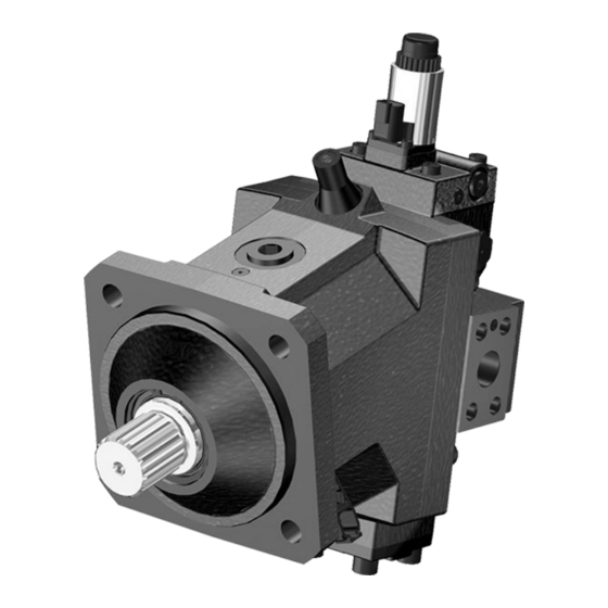
- Page 1 Service Manual H1B 060/080/110/160/210/250 H1 Bent Axis Motors www.danfoss.com...
- Page 2 Add 210 frame size 0500 November 2015 Model code change 0400 July 2015 correct torque values, pages 61, 62 0301 June 2015 add hydraulic controls THHA, THHB 0300 2008-2015 First edition - and next various changes. AA-CB © Danfoss | August 2018 AX00000025en-US0504...
-
Page 3: Table Of Contents
H1 Bent Axis Motors, Size 060/080/110/160/210/250 cm3 Contents Introduction About this manual....................................5 Warranty......................................5 General Instructions..................................5 Safety precautions....................................5 Symbols used in Danfoss literature............................7 H1 general information Design of H1 bent axis motor..............................8 General description..................................10 H1 pictorial diagram..................................11 H1 system schematic..................................12 Technical specifications General specifications.................................. - Page 4 Maximum displacement limiter two-position controls....................58 Servo piston cover – proportional control..........................59 Replace speed sensor................................... 62 Loop flushing spool..................................63 Loop flushing charge relief valve............................. 64 Minimum Displacement limiter..............................65 Torque chart Fasteners, plugs with torque chart............................66 © Danfoss | August 2018 AX00000025en-US0504...
-
Page 5: About This Manual
Only Danfoss global service partners (GSPs) are authorized to perform major repairs.Danfoss trains Global Service Partners and certifies their facilities on a regular basis. You can locate your nearest service partner at www.danfoss.com > Contact us > Danfoss sales and services > Distributor and service partners Warranty Performing installation, maintenance, and minor repairs according to the procedures in this manual will not affect your warranty. - Page 6 Protect yourself from injury. Use proper safety equipment, including safety glasses, at all times. Hazardous material Warning Hydraulic fluid contains hazardous material. Avoid prolonged contact with hydraulic fluid. Always dispose of used hydraulic fluid according to environmental regulations. © Danfoss | August 2018 AX00000025en-US0504...
-
Page 7: Symbols Used In Danfoss Literature
Service Manual H1 Bent Axis Motors, Size 060/080/110/160/210/250 cm3 Introduction Symbols used in Danfoss literature WARNING may result in injury Tip, helpful suggestion CAUTION may result in damage to product or Lubricate with hydraulic fluid property Reusable part Apply grease / petroleum jelly... -
Page 8: H1 General Information
2. Valve segment 3. Bearing plate 4. Tapered roller bearing 5. Loop flushing relief valve 6. Ramp spring 7. Loop flushing shuttle spool 8. Electric proportional control 9. Minimum displacement limiter 10. Speed ring (optional) © Danfoss | August 2018 AX00000025en-US0504... - Page 9 2. Valve segment 3. Bearing plate 4. Tapered roller bearing 5. Loop flushing relief valve 6. Loop flushing shuttle spool 7. Electric two-position control 8. Minimum displacement limiter 9. Speed ring (optional) © Danfoss | August 2018 AX00000025en-US0504 | 9...
-
Page 10: General Description
• Speed • Direction (only group "J", option "S") • Temperature (only group "J", option "S") The electric controls are specifically designed for the Danfoss family of PLUS+1 ® microcontrollers for easy "Plug and Perform" installation. 10 | © Danfoss | August 2018... -
Page 11: H1 Pictorial Diagram
5. Charge Check / High Pressure Relief Valve 14. Pump Swashplate 6. Loop Flushing Valve 15. Input Shaft 7. Pressure Limiter Valve 16. Output Shaft 8. Charge Pressure Relief Valve 17. Reservoir 9. Servo Cylinder 18. to Motor Case © Danfoss | August 2018 AX00000025en-US0504 | 11... -
Page 12: H1 System Schematic
The schematic above shows the function of a hydrostatic transmission using an H1 axial variable displacement pump with electric proportional displacement control (EDC) and an H1 bent axis variable displacement motor with electric proportional control (L*) and integrated loop flushing device. 12 | © Danfoss | August 2018 AX00000025en-US0504... -
Page 13: Technical Specifications
180 HL 4-bolt 200 HL 4-bolt DIN ISO 3019/2, B4 – Pilot Ø160 mm Pilot Ø190 mm Pilot Ø200 mm Cartridge 2-bolt (200 dist.) 2-bolt (224 dist.) 2-bolt (250 dist.) M20 – – © Danfoss | August 2018 AX00000025en-US0504 | 13... -
Page 14: Operating Parameters
-40 °C [-40 °F] Minimum above case pressure (open and closed circuit) See the graphs Required inlet pressure diagrams (for cylinder block filling) on page 16. Air temperature close to the unit. 14 | © Danfoss | August 2018 AX00000025en-US0504... -
Page 15: H1B Speed Range Diagrams For Open And Closed Circuit
Zero degree capability results in a high risk of overspeed and drops in efficiency if the motor operates between 0–20% displacement. For open circuit applications it is not allowed to operate in the intermitent area. For closed circuit applications operating in the intermittent area, please contact your local Danfoss Power Solutions representative. ©... -
Page 16: Required Inlet Pressure Diagrams (For Cylinder Block Filling)
The required pressure is 0 bar at 0 rpm and increases with rpm. For open circuit applications it is not allowed to operate above rated speed. For closed circuit applications operating between rated and max. speed, please contact your local Danfoss Power Solutions representative. 16 | ©... -
Page 17: Open Circuit Requirements
Required inlet pressure diagrams (for cylinder block filling) on page Counter balance valves may be used to maintain the minimum pressure requirements. Also the Danfoss Power Solutions Meter-in / Meter-out PVG technology may be used. Check valves and sufficient charge pressure supply are also possible. -
Page 18: Fluid Specifications
High pressure minus Low pressure [psi] η η Motor volumetric efficiency Motor volumetric efficiency η Mechanical-hydraulic efficiency η Mechanical-hydraulic efficiency η η Motor total efficiency (η • η Motor total efficiency (η • η 18 | © Danfoss | August 2018 AX00000025en-US0504... -
Page 19: Operation
Controls E1, E2, F1, F2, P1, P2, T1, T2, TA, TH, HE, HF Direction of rotation Flow into port A = CounterClockwise Flow into port B = Clockwise P006032 1 means 12 V and 2 means 24 V © Danfoss | August 2018 AX00000025en-US0504 | 19... -
Page 20: Loop Flushing Shuttle Spool
Excessive motor loop flushing flow may result in the inability to build required system pressure in some conditions. Maintain correct charge pressure under all conditions of operation to maintain pump control performance in hydrostatic systems. 20 | © Danfoss | August 2018 AX00000025en-US0504... -
Page 21: Loop Flushing Relief Valve
Loop flushing relief valve schematic P003 491 P003 487 Loop flushing relief valve sizes 40 bar 30 bar 20 bar 10 bar P006 034 Loop flushing flow (l/min) Low system pressure minus case pressure (bar) © Danfoss | August 2018 AX00000025en-US0504 | 21... -
Page 22: Speed Sensor
All Series H1 motors incorporate mechanical displacement limiters. The minimum displacement of the motor is preset at the factory with a set screw in the motor housing. A tamper-proof cap is provided. 22 | © Danfoss | August 2018 AX00000025en-US0504... -
Page 23: Operating Parameters
Maximum pressure is the highest allowable application pressure under any circumstance. For applications which are above the maximum working pressure, please contact Danfoss Minimum pressure must be maintained under all operating conditions to avoid cavitation. -
Page 24: Case Pressure
The minimum temperature relates to the physical properties of component materials. Size heat exchangers too keep the fluid within these limits. Danfoss recommends testing to verify that these temperature limits are not exceeded. 24 | ©... -
Page 25: Fluid And Filter Maintenance
Change filters when changing fluid or when the filter indicator directs. Replace all fluid lost during filter change Warning Hydraulic fluid contains hazardous material. Avoid contact with hydraulic fluid. Always dispose of used hydraulic fluid according to state, and federal environmental regulations. Never reuse hydraulic fluid. © Danfoss | August 2018 AX00000025en-US0504 | 25... -
Page 26: Pressure Measurements
600 bar [8702 psi] Wrench (int. hex): 3/8 in Wrench (int. hex): 9/16 in MA, MB (Axial) 7/8-14 UNF 9/16-18 UNF 600 bar [8702 psi] Wrench (int. hex): 3/8 in Wrench (int. hex): 1/4 in 26 | © Danfoss | August 2018 AX00000025en-US0504... - Page 27 Servo pressure rod end. X1 – Control pressure supply, hydraulic actuator. XA/XB – BPD, PCOR inactive at A/B. Port locations (hydraulic 2-position controls with PCOR; control specific ports only) (Port XA on reverse side) P108924 © Danfoss | August 2018 AX00000025en-US0504 | 27...
-
Page 28: Initial Startup Procedures
12. Shut down the prime mover. 13. Connect the external control input signal. 14. Reconnect the machine function if disconnected earlier. 15. Start the prime mover, checking to ensure the pump remains in neutral. 28 | © Danfoss | August 2018 AX00000025en-US0504... - Page 29 17. Continue to cycle slowly between forward and reverse for at least five minutes. 18. Shut down prime mover. 19. Remove gauges. Replace plugs at the gauge ports. 20. Check reservoir level. Add filtered fluid if needed. The motor/transmission is now ready for operation. © Danfoss | August 2018 AX00000025en-US0504 | 29...
-
Page 30: Troubleshooting
Excessive leakage will cause lower charge pressure Install loop flushing defeat option and measure case and affect performance. flow. If case flow is excessive, motor may require major repair. Contact your Danfoss authorized service center. System operating hot Check Cause... -
Page 31: Excessive Noise Or Vibration
Internal leakage Excessive internal leakage may overheat the Install loop flushing defeat option and monitor case system. flow. If case flow is excessive, motor may require major repair. Contact your Danfoss authorized service center. Excessive noise or vibration Check Cause... -
Page 32: Low Output Torque
Excess internal leakage may cause charge pressure Install loop flushing defeat option and monitor case to decay, reducing output torque. flow. If case flow is excessive, motor may require major repair. Contact your Danfoss authorized service center. 32 | ©... -
Page 33: Required Tools And Standard Procedures
Be careful not to damage solenoids and electrical connections when using straps or chains to remove motor from machine. 5. Perform motor function test. 6. Before re-installing the motor on the machine, drain the system, flush all lines, replace all filters, and fill with new hydraulic fluid. © Danfoss | August 2018 AX00000025en-US0504 | 33... -
Page 34: Adjustments
6. With motor on machine or test stand, verify correct motor function. Refer to Ports and Gauge Information on page 26 for location of gauge ports and suggested gauge sizes. 7. Install new cap (N0120). 34 | © Danfoss | August 2018 AX00000025en-US0504... -
Page 35: Optional Threshold Adjustment - Electric Proportional Controls
5. If adjustment is necessary, remove cap (B0040). Turn the adjusting screw until the signal current matches the model code setting. 6. When threshold is adjusted correctly, stop prime mover, install cap. Run vehicle and test for proper motor operation. 7. Remove from test stand. © Danfoss | August 2018 AX00000025en-US0504 | 35... -
Page 36: Optional Threshold Adjustment - Hydraulic Proportional Controls
5. If adjustment is necessary, remove nut (B0180). Turn the adjusting screw until the X1 pressure matches the model code setting. 6. When threshold is adjusted correctly, stop prime mover, install nut (B0180). Run vehicle and test for proper motor operation. 7. Remove from test stand. 36 | © Danfoss | August 2018 AX00000025en-US0504... -
Page 37: Pressure Compensator Override (Pcor) Adjustment
5. Slowly apply the service brake to continuously increase the load on the system until the wheel speed (setup 7a) or driving speed (setup 7b) decreases by approximately 1/3. 6. Stop machine and turn off engine. 7. Stop data acquisition. © Danfoss | August 2018 AX00000025en-US0504 | 37... - Page 38 Adjusting screw 3 mm 2. Use a 3mm internal hex to hold the PCOR adjusting screw in place and use a 10mm wrench to tighten the lock nut to 8 N-m [6 lbf-ft]. 38 | © Danfoss | August 2018 AX00000025en-US0504...
- Page 39 3. Repeat Testing, Analysis, and Adjustment steps as necessary to reach the desired PCOR setting. H1B PCOR Adjustment PCOR Setting Engine Speed Wheel Speed Begin Application of Service Brake System Pressure Displacement Range Minimum Displacement Max Displacement TIME © Danfoss | August 2018 AX00000025en-US0504 | 39...
-
Page 40: Minor Repair
Pressing the seal and snap-ring together ensures proper installation depth. Using the seal installation tool prevents pressing the seal too deeply. Shaft seal G0020 G0030 40 | © Danfoss | August 2018 AX00000025en-US0504... - Page 41 + 0.10 5.4 mm + 0.10 5 mm [0.2 in] - 0.0 5.15 mm - 0.0 + 0.004 [0.21 in [0.2 in] P107 738E + 0.004 [0.20 in - 0.0 - 0.0 © Danfoss | August 2018 AX00000025en-US0504 | 41...
-
Page 42: Electric Proportional Solenoid Replacement
3. Install cap screws (B0050) using a 4 mm internal hex wrench. Torque screws to 6 N•m [4 lbf•ft]. 4. Reconnect electrical connections and test the motor for proper operation. Replacing solenoid B0050 B0010 4 mm 6 N•m [ 4 lbf•ft] B0035A C0100 42 | © Danfoss | August 2018 AX00000025en-US0504... -
Page 43: Hydraulic Proportional Actuator Replacement
Replacing actuator B0050 B0010 P108828 1. Install cap screws (B0050) using a 4 mm internal hex wrench and torque screws to 6 N•m [4 lbf•ft]. 2. Test the motor for proper operation. © Danfoss | August 2018 AX00000025en-US0504 | 43... -
Page 44: Control Module Replacement
[27 lbf•ft] [27 lbf•ft] Proportional control 10 mm control F0030 115 Nm [85 lbf•ft] C0010 F0030 2 position control F0040 F0040 C0130 C0130 C0130 Electric proportional control Hydraulic proportional control Two position control 44 | © Danfoss | August 2018 AX00000025en-US0504... - Page 45 4. Install four cap screws (C0110 and/or C0120). C0110 and C0120 Wrench Size Screw Control Torque Internal Hex Wrench Electric / Hydraulic proportional 37 N•m 6 mm C0110 [27 lbf•ft] Two-position 115 N•m 10 mm C0110, C0120 [85 lbf•ft] © Danfoss | August 2018 AX00000025en-US0504 | 45...
-
Page 46: Electric Proportional Control Module
Inspect the machined surfaces on the control and the endcap. If you find any nicks or scratches, replace the control or endcap assembly. Check that shuttle ball moves freely in housing (C0025). 46 | © Danfoss | August 2018 AX00000025en-US0504... - Page 47 9. Install solenoid (B0010) using a 4 mm internal hex wrench. 10. Install screws (B0050) with torque to 6 N•m [4 lbf•ft]. 11. Lubricate and install new O-ring (B0025) onto solenoid. 12. Install coil (B0020A). © Danfoss | August 2018 AX00000025en-US0504 | 47...
- Page 48 14. Install coil nut (B0027) and torque to 3.5 N•m [2.6 lbf•ft] using a 26 mm 12-point socket. Do not over torque. 15. Install new O-ring (B0029) and plastic cap (B0040) to solenoid. 48 | © Danfoss | August 2018 AX00000025en-US0504...
-
Page 49: Hydraulic Proportional Control Module
3. Install and torque plugs (C0060) to 8 N•m [6 lbf•ft] using a 1/8 inch internal hex wrench. 4. Lubricate and install spool (C0025) into control block using a 5 mm internal hex wrench, torque to 14 N•m [11 lbf•ft] 5. Install new O-ring (C0050A). © Danfoss | August 2018 AX00000025en-US0504 | 49... - Page 50 8. Install screws (B0050) with torque to 6 N•m [4 lbf•ft]. If replacing the hydraulic actuator, set the threshold pressure to the proper setting. Refer to Adjusting threshold on test stand on page 36 50 | © Danfoss | August 2018 AX00000025en-US0504...
-
Page 51: Electric Two-Position Control Module
9. If necessary, use a 3 mm internal hex wrench to remove orifices (E00T2) and (E00T3). Inspection Clean and inspect the machined surfaces on the control and the endcap. If any nicks or scratches are found, replace the control/endcap assembly. © Danfoss | August 2018 AX00000025en-US0504 | 51... - Page 52 C0050 1/4 in B0024 40 N•m [30 lbf•ft] C0050 B0032 T*G* and P*G* C0050 B0034 C0030 C0010 C0020 C0060 C0060 C0070 E00T3 M223 C0080 C0090 E00T2 B0034 B0032 B0024 B0022 B0028 B0026 52 | © Danfoss | August 2018 AX00000025en-US0504...
- Page 53 9. Install coils (B0022). 10. Lubricate and install new O-rings (B0028). 11. Install coil nuts (B0026) using a 26 mm 12-point socket. Torque to 3.5 N•m [2.6 lbf•ft]. Do not over torque. © Danfoss | August 2018 AX00000025en-US0504 | 53...
-
Page 54: Hydraulic Two-Position Control Module
5. Using a 1/8 inch internal hex wrench, install four plugs (C0060). Torque to 8 N•m [6 lbf•ft]. 6. Using a 1/8 inch internal hex wrench, install plug (C0160). Torque to 25 N•m [18 lbf•ft]. 54 | © Danfoss | August 2018 AX00000025en-US0504... -
Page 55: Hydraulic Two-Position Control Module With Pcor
8. Install three plugs (C0050) using a 1/4 inch internal hex wrench, with torque to 40 N•m [30 lbf•ft]. 9. Install two plugs (C0060) using a 1/8 inch internal hex wrench, with torque to 8 N•m [6 lbf•ft]. © Danfoss | August 2018 AX00000025en-US0504 | 55... -
Page 56: Hydraulic Two-Position Control Module With Pcor And Hydraulic Bpd
6. Install adapter (B0300). Torque to 67 N•m [49 lbf•ft]. 7. Lubricate and install spool (C0020). 8. Using a 1/4 inch internal hex wrench, install plug (C0140). Torque to 14 N•m [10 lbf•ft]. 56 | © Danfoss | August 2018 AX00000025en-US0504... - Page 57 10. Using a 1/4 inch internal hex wrench, install four plugs (C0050). Torque to 40 N•m [30 lbf•ft]. 11. Using a 1/8 inch internal hex wrench, install three plugs (C0060). Torque to 8 N•m [6 lbf•ft]. © Danfoss | August 2018 AX00000025en-US0504 | 57...
-
Page 58: Maximum Displacement Limiter Two-Position Controls
Assembly Maximum displacement limiter assembly P0100 6 mm P0200 P107 866E 1. Install spacer (P0200) and screw (P0100) using a 6 mm internal hex. 2. Torque screw to 37 N•m [28 lbf•ft]. 58 | © Danfoss | August 2018 AX00000025en-US0504... -
Page 59: Servo Piston Cover - Proportional Control
115 N•m [85 lbf•ft] P0020 1. Remove four screws (P0020) using a 10 mm internal hex wrench. 2. Remove servo piston cover (P0010). 3. Remove and discard O-ring (P0030). 4. Remove screw (P0050). © Danfoss | August 2018 AX00000025en-US0504 | 59... - Page 60 Allow seals time to relax before installing piston. 2. Install piston and install screw (P0050). See the table for wrench size below: Wrench size (internal hex) Size 060/080 160/210/250 Wrench size 8 mm 10 mm 12 mm 60 | © Danfoss | August 2018 AX00000025en-US0504...
- Page 61 3. Lubricate and install new O-ring (P0030) and install servo piston cover (P0010). 4. Using a 8 mm or 10 mm internal hex install screws (P0020). Torque to 115 N•m [85 lbf•ft]. © Danfoss | August 2018 AX00000025en-US0504 | 61...
-
Page 62: Replace Speed Sensor
J0010 J0010A 1. Lubricate and install new O-ring (J0010A). 2. Install speed sensor (J0010). 3. Install screw (J0020) using a 5 mm internal hex wrench with torque to 8 N•m [6 lbf•ft]. 62 | © Danfoss | August 2018 AX00000025en-US0504... -
Page 63: Loop Flushing Spool
1. Lubricate and install spool (K0010). 2. Lubricate and install springs (K0020). 3. Lubricate and install new O-rings (K0030A). 4. Install plugs (K0030) using a 24 mm hex wrench with torque to 67 N•m [49 lbf•ft]. © Danfoss | August 2018 AX00000025en-US0504 | 63... -
Page 64: Loop Flushing Charge Relief Valve
1. Install new O-ring (L0050). 2. Using a 24 mm hex wrench, install valve (L00**). Torque to 67 N•m [49 lbf•ft]. Loop flushing charge relief valve replacement L0050 L00** 24 mm 67 N•m [49 lbf•ft] 64 | © Danfoss | August 2018 AX00000025en-US0504... -
Page 65: Minimum Displacement Limiter
(N0020) using a 19mm hex wrench. Torque to 45 N•m [32 lbf•ft]. 3. Install new cap (N0120). Displacement limiter assembly N0010 6 mm 19 mm 45 N•m [32 lb•ft] N0120 N0020 © Danfoss | August 2018 AX00000025en-US0504 | 65... -
Page 66: Torque Chart
9/16 - 18UNF 1/4 internal hex 40 N•m [30 lbf•ft] 9/16-18 UNF (not shown) 1/4 internal hex 40 N•m [30 lbf•ft] C0050 C0060 5/16 - 24UNF 3/8 internal hex 8 N•m [5 lbf•ft] 66 | © Danfoss | August 2018 AX00000025en-US0504... - Page 67 24 mm hex 67 N•m [49 lbf•ft] L00** M18 - 1.5 24 mm hex 67 N•m [49 lbf•ft] 9/16-18 UNF (Axial endcap, not shown) 1/4 internal hex 40 N•m [30 lbf•ft] F0160 © Danfoss | August 2018 AX00000025en-US0504 | 67...
- Page 68 Phone: +86 21 3418 5200 Danfoss can accept no responsibility for possible errors in catalogues, brochures and other printed material. Danfoss reserves the right to alter its products without notice. This also applies to products already on order provided that such alterations can be made without changes being necessary in specifications already agreed.
Need help?
Do you have a question about the H1B 060 and is the answer not in the manual?
Questions and answers