
Related Manuals for Danfoss H1F 060


Summary of Contents for Danfoss H1F 060
- Page 1 Service Manual H1F 060/080/110/160/210/250 H1F Bent Axis Fixed Displacement Motor www.danfoss.com...
- Page 2 H1F Bent Axis Fixed Displacement Motors, Size 060/080/110/160/210/250 Revision history Table of revisions Date Changed April 2024 Added information for 60cc 0201 December 2023 Updated title 0102 November 2023 First edition - and next various changes. 0101 © Danfoss | April 2024 AX465363259664en-000201...
-
Page 3: Table Of Contents
Required tools and standard procedures Minor repair Shaft seal......................................26 H1F Removal....................................26 H1F Assembly.....................................26 Replace speed sensor................................... 28 H1F Speed Sensor Removal..............................28 H1F speed sensor reassembly..............................28 Loop flushing spool..................................29 H1F Loop Flushing Spool Removal............................ 29 © Danfoss | April 2024 AX465363259664en-000201 | 3... - Page 4 Service Manual H1F Bent Axis Fixed Displacement Motors, Size 060/080/110/160/210/250 Contents H1F Loop Flushing Reassembly............................29 H1F Loop Flushing Charge Relief Removal...........................29 Torque chart H1F Fasteners, plugs with torque chart..........................30 © Danfoss | April 2024 AX465363259664en-000201...
-
Page 5: H1F About This Manual
Only Danfoss global service partners (GSPs) are authorized to perform major repairs.Danfoss trains Global Service Partners and certifies their facilities on a regular basis. You can locate your nearest service partner at www.danfoss.com > Contact us > Danfoss sales and services > Distributor and service partners Warranty Performing installation, maintenance, and minor repairs according to the procedures in this manual will not affect your warranty. - Page 6 Protect yourself from injury. Use proper safety equipment, including safety glasses, at all times. Hazardous material Warning Hydraulic fluid contains hazardous material. Avoid prolonged contact with hydraulic fluid. Always dispose of used hydraulic fluid according to environmental regulations. © Danfoss | April 2024 AX465363259664en-000201...
-
Page 7: H1 General Information
Speed sensor options are available to cover all frame sizes and flange styles. They are capable of sensing the following, all in one package: • Speed • Direction (Group "J": option "S" and option "B") • Temperature (Group "J": options "S" and option "B") © Danfoss | April 2024 AX465363259664en-000201 | 7... -
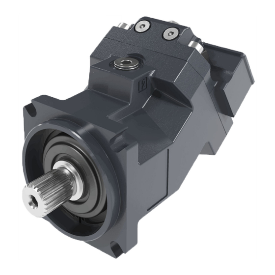
Page 8: H1F Pictorial Diagram
5. Charge Check / High Pressure Relief Valve 14. Input Shaft 6. Loop Flushing Valve 15. Output Shaft 7. Pressure Limiter Valve 16. Reservoir 8. Charge Pressure Relief Valve 17. to Motor Case 9. Servo Cylinder © Danfoss | April 2024 AX465363259664en-000201... -
Page 9: H1F System Schematic
The schematic above shows the function of a hydrostatic transmission using an H1 axial variable displacement pump with electric proportional displacement control (EDC) and an H1 fixed displacement motor with integrated loop flushing device. © Danfoss | April 2024 AX465363259664en-000201 | 9... -
Page 10: Technical Specifications
18.5 kg [40.8] Cartridge Mounting flange Configuration Size 127-4 (SAE C) 4-bolt SAE ISO 3019/1 Flange 125 B4 HL 4-bolt 140 HL 4-bolt DIN ISO 3019/2, B4 Pilot dia 160mm, 2-bolt (200 dist) Cartridge © 10 | Danfoss | April 2024 AX465363259664en-000201... -
Page 11: H1F Operating Parameters
This pressure ensures that the cylinder block will be properly filled and that there is no pulling between piston and shaft. The required pressure is 0 bar at 0 rpm and increases with rpm. © Danfoss | April 2024 AX465363259664en-000201 | 11... -
Page 12: H1F Open Circuit Requirements
Required inlet pressure table (for cylinder block filling) on page 11 . Counter balance valves may be used to maintain the minimum pressure requirements. Danfoss meter-in / meter-out PVG technology may be used. Check valves and sufficient charge pressure supply are also possible. -
Page 13: Fluid Specifications
High pressure minus Low pressure [psi] η Motor volumetric efficiency η Motor volumetric efficiency Mechanical-hydraulic efficiency Mechanical-hydraulic efficiency η η η Motor total efficiency (η • η η Motor total efficiency (η • η © Danfoss | April 2024 AX465363259664en-000201 | 13... -
Page 14: Operation
Excessive motor loop flushing flow may result in the inability to build required system pressure in some conditions. Maintain correct charge pressure under all conditions of operation to maintain pump control performance in hydrostatic systems. © 14 | Danfoss | April 2024 AX465363259664en-000201... -
Page 15: H1F Loop Flushing Relief Valve
Loop flushing relief valve schematic P003 491 P003 487 Loop flushing relief valve sizes 40 bar 30 bar 20 bar 10 bar P006 034 Loop flushing flow (l/min) Low system pressure minus case pressure (bar) © Danfoss | April 2024 AX465363259664en-000201 | 15... -
Page 16: Speed Sensor
Excessive axial shaft loading during installation of motors with speed sensors and cartridge housings must be avoided. High axial shaft loads during installation of motors can lead to a movement of the shaft and damage the speed sensor. © 16 | Danfoss | April 2024 AX465363259664en-000201... -
Page 17: Operating Parameters
Maximum pressure is the highest allowable application pressure under any circumstance. For applications which are above the maximum working pressure, please contact Danfoss Minimum pressure must be maintained under all operating conditions to avoid cavitation. -
Page 18: External Shaft Seal Pressure
The minimum temperature relates to the physical properties of component materials. Size heat exchangers too keep the fluid within these limits. Danfoss recommends testing to verify that these temperature limits are not exceeded. ©... -
Page 19: Fluid And Filter Maintenance
Change filters when changing fluid or when the filter indicator directs. Replace all fluid lost during filter change Warning Hydraulic fluid contains hazardous material. Avoid contact with hydraulic fluid. Always dispose of used hydraulic fluid according to state, and federal environmental regulations. Never reuse hydraulic fluid. © Danfoss | April 2024 AX465363259664en-000201 | 19... -
Page 20: Pressure Measurements
Ports and gauge Information Port Size 060/080 Pressure obtained M22 x 1.5 10 bar [145 psi] L1, L2 Wrench (int. hex): 17 mm Case drain M14 x 1.5 Wrench (int. hex): 12 mm © 20 | Danfoss | April 2024 AX465363259664en-000201... -
Page 21: Initial Startup Procedures
12. Shut down the prime mover. 13. Connect the external control input signal. 14. Reconnect the machine function if disconnected earlier. 15. Start the prime mover, checking to ensure the pump remains in neutral. © Danfoss | April 2024 AX465363259664en-000201 | 21... - Page 22 17. Continue to cycle slowly between forward and reverse for at least five minutes. 18. Shut down prime mover. 19. Remove gauges. Replace plugs at the gauge ports. 20. Check reservoir level. Add filtered fluid if needed. The motor/transmission is now ready for operation. © 22 | Danfoss | April 2024 AX465363259664en-000201...
-
Page 23: Troubleshooting
Excessive leakage will cause lower charge pressure Install loop flushing defeat option and measure case and affect performance. flow. If case flow is excessive, motor may require major repair. Contact your Danfoss authorized service center. System operating hot Check Cause... -
Page 24: Motor Operates Normally In One Direction Only
Excess internal leakage may cause lower charge Install loop flushing defeat option and measure case pressure and affect motor performance including flow. If case flow is excessive, motor may require major output speed. repair. Contact your Danfoss authorized service center. H1F Low output Torque Check Cause... -
Page 25: Required Tools And Standard Procedures
Be careful not to damage solenoids and electrical connections when using straps or chains to remove motor from machine. 5. Perform motor function test. 6. Before re-installing the motor on the machine, drain the system, flush all lines, replace all filters, and fill with new hydraulic fluid. © Danfoss | April 2024 AX465363259664en-000201 | 25... -
Page 26: Minor Repair
Pressing the seal and snap-ring together ensures proper installation depth. Using the seal installation tool prevents pressing the seal too deeply. Shaft seal © 26 | Danfoss | April 2024 AX465363259664en-000201... - Page 27 + 0.10 5.4 mm + 0.10 5 mm [0.2 in] - 0.0 5.15 mm - 0.0 + 0.004 [0.21 in [0.2 in] P107 738E + 0.004 [0.20 in - 0.0 - 0.0 © Danfoss | April 2024 AX465363259664en-000201 | 27...
-
Page 28: Replace Speed Sensor
*J0041 J0020 1. Lubricate and install new O-ring (J0041). 2. Install speed sensor (J0010). 3. Install screw (J0020) using a 5 mm internal hex wrench with torque to 8 N•m [6 lbf•ft]. © 28 | Danfoss | April 2024 AX465363259664en-000201... -
Page 29: Loop Flushing Spool
H1F Loop Flushing Charge Relief Removal 1. Using a 24 mm hex wrench remove valve (L00**) 2. Remove and discard O-ring (L0150). Do not disassemble valve. If you suspect malfunction, replace valve. © Danfoss | April 2024 AX465363259664en-000201 | 29... - Page 30 1/4 internal hex 40 N•m [30 lbf•ft] F0160 060/080 M14 - 1.5 (SAE and DIN flange) 12 mm internal 47 N•m [35 lbf•ft] G0080 060/080 M22-1.5 17 mm internal 70 N•m [52 lbf•lb] G0060/G0061 © 30 | Danfoss | April 2024 AX465363259664en-000201...
- Page 31 Plug size and torque chart (continued) Item Frame size O-ring plug Wrench size Torque M18 - 1.5 24 mm hex 67 N•m [49 lbf•ft] K0040/K0050 M18 - 1.5 24 mm hex 67 N•m [49 lbf•ft] L0100 © Danfoss | April 2024 AX465363259664en-000201 | 31...
- Page 32 Phone: +86 21 2080 6201 Danfoss can accept no responsibility for possible errors in catalogues, brochures and other printed material. Danfoss reserves the right to alter its products without notice. This also applies to products already on order provided that such alterations can be made without subsequent changes being necessary in specifications already agreed.
Need help?
Do you have a question about the H1F 060 and is the answer not in the manual?
Questions and answers