Table of Contents
Advertisement
Quick Links
Advertisement
Table of Contents

Related Manuals for Toshiba LQ500


Summary of Contents for Toshiba LQ500
- Page 1 6 F 8 A 0 5 2 1 OPERATION MANUAL DENSITY METER TYPE LQ500...
- Page 3 ■ Notice Do not copy or transcribe this manual in part or entirety without written permission from Toshiba. The manual is subject to change without notice. Although we tried hard to make this manual error free, if you find any errors or unclear passages, kindly let us know.
-
Page 4: Safety Precautions
6 F 8 A 0 5 2 1 SAFETY PRECAUTIONS Important information is shown on the product itself and in the operation manual to protect users from bodily injuries and property damages, and to enable them to use the product safely and correctly. -
Page 5: Contents
SAFETY PRECAUTIONS (Continued) For a safe use of the LQ500 Density Meter, take precautions described in this manual and observe ordinances in making the installation and operation. Toshiba is not responsible for any accident arising from the use that does not conform to above. - Page 6 6 F 8 A 0 5 2 1 SAFETY PRECAUTIONS (Continued) WIRING PRECAUTIONS Yellow WARNING ■Be sure to install a fuse and a ■Be sure to ground the switch to disconnect the equipment using a grounding equipment from the power wire separate from those used source.
-
Page 7: Contents
6 F 8 A 0 5 2 1 Contents SAFETY PRECAUTIONS (Continued) PRECAUTIONS REGARDING MAINTENANCE, INSPECTION, AND PARTS REPLACEMENT Yellow WARNING ■Be sure to set the power ■Be sure to set the power switch on the equipment to the switch on the equipment to the OFF position before doing OFF position before replacing maintenance or inspection... - Page 8 This product is not designed or manufactured for the purpose of applying to the systems, such as shown below, which require the level of safety that directly concerns with human life. When your use includes potential applications in those systems, contact Toshiba for consultation. (Example) •...
-
Page 9: [Note] Sign
6 F 8 A 0 5 2 1 Contents [NOTE] Sign When an explanation is made in the text regarding the Safety Precautions, the [NOTE] sign shown below appears in the left margin of a page. The [NOTE] gives you directions to follow in the following instances. -
Page 10: Important Notes Of Use Of Lq500 Density Meter
LQ500 Density Meter and safely use it over a long period of time. • Toshiba is not held responsible for any fault or result caused by not observing the precautions described in this manual or by not observing the laws or regulations in installing or using the product. -
Page 11: Contents
Otherwise, the density meter may be broken, resulting in malfunction or fault. [NOTE] Before returning your meter to Toshiba for repair, etc., make sure to inform us about the measured matter remaining in the density meter pipe, including whether it is dangerous or not to touch the material and then clean the meter so that no measured matter remains in its pipe. -
Page 12: Table Of Contents
6 F 8 A 0 5 2 1 Contents SAFETY PRECAUTIONS......................2 [NOTE] SIGN ..........................7 IMPORTANT NOTES OF USE OF LQ500 DENSITY METER ..........8 OVERVIEW ........................13 Principle of Measurement....................13 Features......................... 14 2. UNPACKING ........................15 Standard Components ..................... 15 Standard Accessories ..................... 15 3. - Page 13 6 F 8 A 0 5 2 1 Contents 5.2.15 Additives correction display and operating procedures ..........51 5.2.16 Other menus display and operating procedures ............54 6. OPERATIONS........................56 Procedures for Preparing and Running ................56 Preparations before Turning on Power ................57 Power on and Preparations for Measuring................
- Page 14 6 F 8 A 0 5 2 1 Contents 10. VARIOUS FUNCTIONS ....................82 10.1 Various Functions and their Outlines................. 82 10.2 Moving Average....................... 83 10.2.1 Function of moving average..................83 10.2.2 Setting of the moving average times................83 10.2.3 Cautions in using the moving average function ............. 83 10.3 Change-rate limit......................
-
Page 15: Overview
6 F 8 A 0 5 2 1 1 OVERVIEW The LQ500 Density Meter measures the density of a substance that flows through a pipe by means of a phase difference method using microwaves. This method is little affected by the presence of contamination. It uses no moving mechanical parts or mechanism that is often used in other measuring methods for cleaning, sampling, or defoaming. -
Page 16: Features
(6) Being of the flow-through type, the new method is capable of continuous measurement. As others, the new density meter model LQ500 boasts of the following features. (7) Can easily change the measurement range. (8) The operation is simple because complex processings such as density calculation and correction, etc. -
Page 17: Unpacking
6 F 8 A 0 5 2 1 2. UNPACKING Check items by the following list and table at unpacking. 2.1 Standard Components (1) Density Meter : 1 unit (One unit each of Detector and Converter,) (2) Standard accessories : 1 unit (One set of cables,Fuse,Operation manual) <Supplementary Explanation>... -
Page 18: Installation
6 F 8 A 0 5 2 1 3. INSTALLATION 3.1 Precautions for Installation WARNING ■The meter is heavy. To move ■Do not operate where there is the meter for relocation or a possibility of leakage of installation, a qualified operator flammable or explosive gas. -
Page 19: Installation Location
6 F 8 A 0 5 2 1 3.2 Installation Location [NOTE] ◆ Determine an indoor installation place in accordance with the following instructions. (1) Choose a place that is free of vibrations and corrosive gasses, and has ample space for maintenance. -
Page 20: Installation And Piping
6 F 8 A 0 5 2 1 3.3 Installation and Piping Figures 3.3.1 through 3.3.4 are examples of density meter installation. [NOTE] (1) Install the meter in a place where density distribution is uniform. (2) Avoid such a location where the measured matter will settle and build up on the bottom of the density meter. - Page 21 6 F 8 A 0 5 2 1 [NOTE] ◆Sampling valve: Used to extract fluids for manual analysis. Install this valve to the side of the pipe in the case of horizontal installation. It is recommended that a 1-inch ball valve be installed to the side of the pipe. ◆Zero point water valve: Used to supply drinking water (density or consistency 0%) to the detector pipe for zero point adjustment.
- Page 22 6 F 8 A 0 5 2 1 Stop valve Stop valve Air release valve Zero point water valve Zero water piping Density meter Bypass piping Drain valve Drain Stop valve Direction of flow Upward Fig.3.3.4 Meter mounted vertically [NOTE] When you lift the meter using a lifting wire for relocation, installation or for other purposes, use the wire so that the wire does not touch the RF section of the density meter.
-
Page 23: Precautions For Wiring
6 F 8 A 0 5 2 1 3.4 Precautions for wiring WARNING Yellow ■Be sure to install a fuse and a ■Be sure to ground the switch to disconnect the equipment using a grounding equipment from the power wire separate from those used source. -
Page 24: Wiring
6 F 8 A 0 5 2 1 3.5 Wiring Figure 3.5.1 on the next page shows connections to the density meter and the external units. Figure 3.5.2 shows wiring assignment to a converter terminal. Refer to these figures for correct wiring. [IMPORTANT] (1) A density meter has to be separated from the power supply line when performing the maintenance and inspection operation. - Page 25 6 F 8 A 0 5 2 1 Ec+ Conductivity Converter signal input (4 ~ 20mADC) Power 100 to 240VAC, 50/60Hz CVVS Tx+ Tx+ section Ground (PE) (Ground resistance: 100Ω or less) External sync contact input (Contact capacity: 24VDC, 1A or more) COM1 Density meter error or Communication...
- Page 26 6 F 8 A 0 5 2 1 Terminal block +24V T x+ EC+ T x− Rx− EC− Communication Power supply Conductivity signal input (4 ~ 20 mADC) Figure3.5.3 Terminals arrangement inside the RF section [NOTE] For connection between the converter and the RF section, connect cables according to the band marks attached to the power cable (1) and the communication cable (2).
-
Page 27: Part Names And Functions
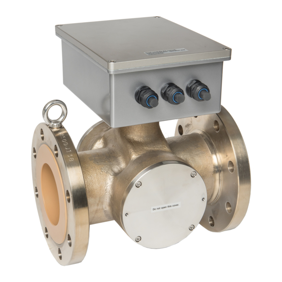
6 F 8 A 0 5 2 1 4. PART NAMES AND FUNCTIONS The detector is integrated with the converter in LQ500 Density meter. 4.1 Detector RF section (2) Applicator section (1) Main pipe (3) Temperature detector Fig.4.1.1 Detector 25 ... - Page 28 Main pipe Refers to the part connected to the pipe line of a measured object. FLANGE is JIS 10K or equivalent. Contact Toshiba for connections other than this method (shown left). Applicator mount The applicators (antenna) for transmitting and receiving microwaves are built inside. The applicator on the front in Fig.4.1 is for transmitting and the rear is for receiving.
-
Page 29: Converter
6 F 8 A 0 5 2 1 4.2 Converter Figure 4.2 shows the converter with its door open. (4) [MEASURE] (5) [ALARM] indicator indicator (3) [POWER] indicator (6) LCD indicator (7) Setting keys (1) Power switch FUSE (2) Fuse 2A(T) FUSE 250V... -
Page 30: Contents
6 F 8 A 0 5 2 1 [NOTE] Install the converter cover when operating the density meter. In addition, tighten securely the screws of the converter cover. If screws are not tightened enough, moisture, dust or other particles enters the converter and can cause a converter failure. [POWER] switch The power switch for the density meter. -
Page 31: Operation Procedure
6 F 8 A 0 5 2 1 5. OPERATION PROCEDURE 5.1 Parameter and Set Values The set values and setting ranges by parameter at the time of factory shipment are listed in Table 5.1.1 below. Table 5.1.1 Parameters and Set Values (No.1) Measurement Condition Parameter Unit Ex-factory Set Value... - Page 32 6 F 8 A 0 5 2 1 Table 5.1.1 Parameters and Set Values (No.2) Ex-factory Set Measurement Condition Parameter Unit Setting Range Values Availability of additives correction No (Without loading − OFF / ON (AF) material correction) Display density type of −...
-
Page 33: Menus And Operations
6 F 8 A 0 5 2 1 5.2 Menus and operations Operations should be done with five keys for setting, in combination with the LCD display. This section shows menus and operations. 5.2.1. Main menu Main menu is composed of three basic menus shown below. Table 5.2.1 shows the functions of each menu and performances when selected. -
Page 34: Setting Keys
6 F 8 A 0 5 2 1 5.2.2 Setting keys Five setting keys are available. The basic methods for using them are described in Table 5.2.2. For specification information, please refer to their respective operating procedures. Table 5.2.2 Basic Methods for Using Operation Keys Setting Notation in Basic Use... -
Page 35: Menu Display
6 F 8 A 0 5 2 1 5.2.3 Menu display The menu display of the converter LCD display section has a hierarchical structure as shown in Table 5.2.3. Note: Occasionally using some abbreviated terms as well, actual LCD displays differ from Table 5.2.3. - Page 36 6 F 8 A 0 5 2 1 Table 5.2.3 Menu Display (2) Menu 1 Menu 2 Menu 3 Menu 4 Setting Parameter Upper density measurement range Setting the upper density measurement range menu setting (UR) (UR) Lower density measurement range Setting the lower d ensity measurement range (LR) (LR) Density line slope (a)
- Page 37 6 F 8 A 0 5 2 1 Table 5.2.3 Menu Display (3) Menu 1 Menu 2 Menu 3 Menu 4 Setting Additives Availability of additives correction Selecting the availability of additives correction menu correction (AF) (AF) Display density type (Ad) Selecting the display density type (Ad) Output density type (Ac) Displaying the output density type (Ac)
-
Page 38: Monitoring Menu Display And Operating Procedures
6 F 8 A 0 5 2 1 5.2.4 Monitoring menu display and operating procedures 1 : MONITORING MENU 2 : SETTING MENU 3 : MEASURING MODE Move the cursor to "1" with [→] key, and Note: In actual display, the cursor is [ESC] press [SET] key. -
Page 39: Setting Menu Display And Operating Procedures
6 F 8 A 0 5 2 1 5.2.5. Setting menu display and operating procedures 1 : MONITORING MENU 2 : SETTING MENU 3 : MEASURING MODE Move the cursor to "2" with [→] key, and press [SET] key. [ESC] (Previous Menu) When [2: SETTING MENU] is selected, the density output... -
Page 40: Measuring Mode Display And Operating Procedures
6 F 8 A 0 5 2 1 5.2.6 Measuring mode display and operating procedures 1 : MONITORING MENU 2 : SETTING MENU 3 : MEASURING MODE Move the cursor to "3" with [→] key, and press [SET] key. [ESC] (Previous Menu) OP:MEASURING MODE... - Page 41 6 F 8 A 0 5 2 1 [DN] (Pre. menu) a: DENSITY LINE SLOPE The set value of "density line slope" of the arithmetic expression for calculating the density DATA: 0.0840 [ESC] from the phase measurement data, etc. can be verified.
- Page 42 6 F 8 A 0 5 2 1 [DN] (Pre. menu) The set value of the RF correction factor used for density cG:RF COEF. calculation can be verified. Before shipment, this value is DATA:0.00 already set in accordance with the product's characteristics in [ESC] the shipping test.
-
Page 43: Measured Values Display And Operating Procedures
6 F 8 A 0 5 2 1 5.2.8 Measured values display and operating procedures 1 : READ PARAMETERS 2 : MEASURED VALUES 3 : SELF-DIAGNOSIS [ESC] Move the cursor to "2" with [→] key, and press [SET] key to (Previous select [ 2:MEASURED VALUES] Menu) - Page 44 6 F 8 A 0 5 2 1 [DN] (Pre. menu) F:MICROWAVE COEF. The micro wave signal constant can be verified. DATA : 1910 Normally, the value is 1825 to 1975. [ESC] (Previous [ESC] RETURN Menu) [DN] [UP] (Pre. menu) (Next menu) G:RF DATA.
-
Page 45: Parameter Setting Display And Operating Procedures
6 F 8 A 0 5 2 1 5.2.10 Parameter setting display and operating procedures 5:SET PARAMETERS 6:ZERO CALIBRATION 7:SPAN CALIBRATION 8:ANGLE ROTATION Move the cursor to "5" with [→] key, and press [SET] key to select[ 5:SET PARAMETERS] [SET](Set) UR:UPPER RANGE UR:UPPER RANGE DATA:... - Page 46 6 F 8 A 0 5 2 1 [DN] (Pre. menu) dt:DELAYED SYNC.TIME dt:DELAYED SYNC.TIME [SET](Set) DATA: 0.5 RANGE :0.1-99.9 min DATA : 00.5 [SET] CHANGE [SET](Fix) [ESC] [SET] SET,[ESC] CANCEL [ESC] RETURN (Previous [ESC](Cancel) Menu) In external synchronized operations, the delayed time from when the [DN] [UP] external contact input is turned ON until the measurement starts is set.
- Page 47 6 F 8 A 0 5 2 1 [DN] (Pre. menu) zG:ZERO RF DATA zG:ZERO RF DATA [SET](Set) RANGE :0.00-100.00 (C DATA: 50.00 [ESC] [SET](Fix) DATA: 050.00 [SET] CHANGE (Previous [SET] SET,[ESC] CANCEL [ESC](Cancel) [ESC] RETURN Menu) The zero-point RF data can be set in this menu through [DN] [UP] manual input.
-
Page 48: Zero Calibration Display And Operating Procedures
6 F 8 A 0 5 2 1 5.2.11 Zero calibration display and operating procedures 5:SET PARAMETERS 6:ZERO CALIBRATION 7:SPAN CALIBRATION 8:ANGLE ROTATION Move the cursor to "6" with [→] key, and press [SET] key to select [6:ZERO CALIBRATION] * ZERO CAL ZERO POINT 87.93 °... -
Page 49: Phase Angle Rotation Correction Display And Operating Procedures
6 F 8 A 0 5 2 1 5.2.13 Phase angle rotation correction display and operating procedures 5:SET PARAMETERS 6:ZERO CALIBRATION 7:SPAN CALIBRATION 8:ANGLE ROTATION Move the cursor to "8" with [→] key, and press [SET] key to select [8:ANGLE ROTATION] [SET](Set) UH:UPPER ANGLE UH:UPPER ANGLE... -
Page 50: Linearize/Conductity Correction Display And Operating Procedures
6 F 8 A 0 5 2 1 5.2.14 Linearize/conductity correction display and operating procedures 9:LINEARIZ/CNDUCTVTY 10:ADDITIVES CORRECT 11:OTHERS Move the cursor to "9" with [→] key, and press [SET] key to select [ 9:LINEARIZ/CNDUCTVTY] LA:DENSITY A LA:DENSITY A [SET](Set) RANGE :0.00-99.99 DATA :0.60 [ESC]... - Page 51 6 F 8 A 0 5 2 1 49 ...
- Page 52 6 F 8 A 0 5 2 1 [DN] (Pre. menu) [SET](Set) EC:CONDUCTIVITY MANU/LINE SELECTION [SET](Fix in DATA: 1.23(LINE) [ESC] RANGE :MANU/LINE "LINE mode") (Previous [SET] CHANGE DATA:(LINE) Menu) [ESC] RETURN [ESC](Cancel) [SET] SET,[ESC] CANCEL [UP] and [DN] is used to switch between MANU/LINE to select the method for setting the electric conductivity.
-
Page 53: Additives Correction Display And Operating Procedures
6 F 8 A 0 5 2 1 5.2.15 Additives correction display and operating procedures 9:LINEARIZ/CNDUCTVTY 10:ADDITIVES CORRECT 11:OTHERS Move the cursor to "10" with [→] key, and press [SET] key to select [10:ADDITIVES CORRECT ] [SET](Set) AF:ADDITIVES COMP. AF:ADDITIVES COMP. DATA :ON RANGE :OFF/ON [SET](Fix) - Page 54 6 F 8 A 0 5 2 1 [DN] (Pre. menu) [SET](Set) Ap:PARAMETER SET NO. Ap:PARAMETER SET NO. [SET](Fix) DATA: 01 RANGE:1 - 10 DATA:01 [SET] CHANGE [ESC] [ESC](Cancel) [SET] SET,[ESC] CANCEL [ESC] RETURN (Previous Menu) Ten parameter sets ( tables for each brands) can be registered for additives correction.
- Page 55 6 F 8 A 0 5 2 1 [DN] (Pre. menu) [SET](Set) s5:ADDITIVE SENS. s5:ADDITIVE SENS. DATA: 0.00 RANGE :−9.99 - 9.99 [SET](Fix) [SET] CHANGE [ESC] DATA: 0.00 [ESC] RETURN (Previous [SET] SET,[ESC] CANCEL [ESC](Cancel) Menu) [DN] [UP] (Pre. menu) (Next menu) [SET](Set) R1:ADDITIVE RATIO...
-
Page 56: Other Menus Display And Operating Procedures
6 F 8 A 0 5 2 1 5.2.16 Other menus display and operating procedures 9:LINEARIZ/CNDUCTVTY 10:ADDITIVES CORRECT 11:OTHERS Move the cursor to "11" with [→] key, and press [SET] key to select [ 11:OTHERS] [SET](Set) ho:4-20mA IN [EXT] ho:4-20mA IN [EXT] DATA :4mA RANGE :LAST/4mA/TEST [SET](Fix) - Page 57 6 F 8 A 0 5 2 1 [DN] (Pre. menu) C4:DensityMultiplier [SET](Set) C4:DensityMultiplier RANGE :0.000-9.999 DATA: 1.000 [SET](Fix) DATA: 1.000 [SET] CHANGE [ESC] [ESC](Cancel) [SET] SET,[ESC] CANCEL [ESC] RETURN (Previous Menu) [DN] [UP] (Pre. menu) (Next menu) NA:N AUTO ADJUSTMENT [SET](Set) NA:N AUTO ADJUSTMENT RANGE :ON/OFF...
-
Page 58: Operations
6 F 8 A 0 5 2 1 6. OPERATIONS 6.1 Procedures for Preparing and Running Make preparations and perform operations, that is, density measurements, in accordance with the following procedure. Verifying the piping See 6.2(1) See 6.2(2) Verifying the valve closure See 6.2(3) Verifying the cable connection Verifying the converter power-ON &... -
Page 59: Preparations Before Turning On Power
6 F 8 A 0 5 2 1 6.2 Preparations before Turning on Power (1) Check piping Check piping and ensure that there are no loose nuts and bolts, or missing gaskets. Make sure that the density meter is properly connected in the pipeline. See the section 3.3, Installation and Piping. -
Page 60: Verifying And Setting Measurement Conditions
⑤ For other measurement conditions, the standard values are set. Therefore, it is normally unnecessary to change these settings. [NOTE] “10 VARIOUS FUNCTION” describes various functions of the Density Meter LQ500. If necessary, make additional settings for using these functions appropriately. (2) Verifications at the time of normal power-ON In the event that measurement conditions of the converter are already set with the operation not being the first one since installation, verify the set value while referring to (1). - Page 61 6 F 8 A 0 5 2 1 59 ...
-
Page 62: Zero Calibration
6 F 8 A 0 5 2 1 6.4 Zero Calibration All the density meters are calibrated for zero point [zero point phase ( θ ) and zero point water temperature (T ) ] at the time of shipment and parameters are set correctly. You do not need to calibrate the meter for zero point before using it at site. - Page 63 6 F 8 A 0 5 2 1 (8) Clean inside of the detector main pipe When the pipeline where the detector is installed is filled with zero water, open the drain valve to let out the water from the pipeline. Clean inside of the pipeline where the density meter is installed by repeating Steps (7) and (8) until the water density can be said to be zero against the density of the object fluid.
-
Page 64: Span Calibration
6 F 8 A 0 5 2 1 6.5 Span Calibration Span calibration is for adjusting the readings of the density meter to the values determined by manual (off-line) analysis. For information on the converter operation and the LCD display regarding span calibration, please refer to Subsection 5.2.12. - Page 65 6 F 8 A 0 5 2 1 (5) Setting the density multiplier (5-1) Switching to the setting mode (see Subsection 5.2.5) First of all, press the [ESC] key of the converter several times (normally once although this varies with the operation status). Next, use the [→] key to move the LCD indicator cursor to the menu number "2"...
-
Page 66: Operation
6 F 8 A 0 5 2 1 6.6 Operation (1) Startup (see Subsection 5.2.5) When the power is turned ON, the menu setup is automatically changed to the measuring mode (the state of "1: MONITORING MENU"), thus starting the density measurement. If the meter is in setting mode (the state of "2:SETTING MENU"), the density measurement operation is started by pressing the [ESC] key several times (varying between one to three times depending on the operation status) and thus pulling the menu setup out of the setting mode. -
Page 67: External Synchronized Operation
6 F 8 A 0 5 2 1 6.7 External Synchronized Operation This operation mode is used in the event that the measured matter does not flow continuously or the interior of the detector is temporarily left empty due to the intermittent operation of the shifting pump to the pipe line on which the density meter is installed. -
Page 68: Setting The External Synchronized Operation
6 F 8 A 0 5 2 1 6.7.2 Setting the external synchronized operation (1) Setting the delayed time (see Subsection 5.2.10) (1-1) Switching to the setting mode (see Subsection 5.2.5) First of all, press the [ESC] key of the converter several times (normally once although this varies with the operation status) to return to the initial menu display. -
Page 69: Functions Related To Operation
ON/OFF. 6.8 Functions Related to Operation To enable you to use the Density Meter Type LQ500 more appropriately in various processes and situations, the device is equipped with various functions including the moving average, the change-rate limit, the electric conductivity correction, the additive correction, the linearizer and the density multiplier switching by external signals. -
Page 70: Maintenance
6 F 8 A 0 5 2 1 7. MAINTENANCE 7.1 Precautions for Maintenance, Inspection and Parts Replacement WARNING Yellow ■Be sure to set the power ■Be sure to set the power switch on the equipment to the switch on the equipment to the OFF position before doing OFF position before replacing maintenance or inspection... -
Page 71: Maintenance And Inspection Items
6 F 8 A 0 5 2 1 7.2 Maintenance and Inspection Items Periodic maintenance and inspection is necessary for reliable measurement over a long period of time. Since the density meter has no mechanically moving parts, however, it does not require replacement of mechanism elements in a normal operating environment. - Page 72 The service life is about 10 years at the ambient temperature of 20°C or about 3 years at 50°C. For stable use of the meter for many years, it is desirable to replace these parts in time. When replacing the capacitors, please contact Toshiba's Service Dept.
-
Page 73: Troubleshooting
6 F 8 A 0 5 2 1 8. TROUBLESHOOTING 8.1 Troubleshooting If any trouble has developed, make a careful check and take appropriate steps. Table 8.1 shows possible troubles, their causes, and remedies. If anything wrong occurs, refer to the table below and take the necessary steps. - Page 74 6 F 8 A 0 5 2 1 Table 8.1 Troubleshooting (2) Trouble Cause Remedy Inappropriate density Calibrate span as described in correction factor setting. section 6.5. Very slow flow can be the cause. Air accumulates and keep Make the flow faster by using staying inside the detector.
-
Page 75: Error Indications And Recovery Operations
6 F 8 A 0 5 2 1 8.2 Error Indications and Recovery Operations If an error occurs to the density meter, the error indicator [ALARM] will light up and a contact signal (OFF) will be output. Check the self-diagnosis data for any faulty values in accordance with the following steps. (1) Monitor menu display (see Subsection 5.2.4) First of all, press the [ESC] key of the converter several times (normally once although this varies with the operation status) to return to the initial menu display. - Page 76 6 F 8 A 0 5 2 1 Table. 8.2 Self-diagnosis data Data Item Data (Numeric value range; Data Status normal data range, status) Symbol Item name • Normal [GOOD] • Warning [WARNING.] Status Whether the phase [STATUS] measurement operation is normally functioning or not can be verified.
-
Page 77: Corrections In Density Calculation
6 F 8 A 0 5 2 1 9. CORRECTIONS IN DENSITY CALCULATION This density meter, which operates on the basis of phase difference measurement by microwaves makes automatic corrections to the measured phase angel for the fluid temperature and phase angel rotation before making the density calculations for the measured substance. -
Page 78: Various Kinds Of Corrections
6 F 8 A 0 5 2 1 9.2 Various Kinds of Corrections 9.2.1 Phase angle rotation correction The phase is available only from 0 degree to 360 degrees. If the phase incrementally reaches 360 degrees, it returns to 0 degree, from which it keeps incrementing again. If the phase decreasingly reaches 0 degrees, it returns to 360 degrees, from which it keeps decreasing again. -
Page 79: Rf Correction
6 F 8 A 0 5 2 1 9.2.3 RF correction In addition to the fluid temperature correction, the density meter is equipped with the RF correction function in accordance with the features of the converter. The correction is performed on θ2 as follows to obtain the phase difference △θ. -
Page 80: Phase Angle Rotation Correction (Details)
6 F 8 A 0 5 2 1 9.3 Phase Angle Rotation Correction (Details) This section describes the special setups and actions required for cases of measuring high density. In normal measurement, it is unnecessary to be aware of the phase angle rotation correction, which is performed automatically. -
Page 81: Restrictions And Invalidation In Applying The Automatic Adjustment Of Phase Angle Rotations
6 F 8 A 0 5 2 1 In Table 9.3.1 above, C: Density multiplier (Varies with the character of the measured matter.) a: Density slope (A constant determined by the meter size) The values of the respective meter size in C = 1, 0.7 and 1.8 as examples of the value X in which N is judged to be too large are listed in Table 9.3.2. -
Page 82: Actions After Invalidating The Automatic Adjustment Of Phase Angle Rotations
6 F 8 A 0 5 2 1 There are two ways of dealing with such a case. One is to automatically invalidate the function of automatic adjustment of phase angle rotations by provisionally setting a sufficiently small value such as about 0.5 for the density multiplier C so that Xmax is smaller than the upper density measurement range. -
Page 83: Return To The Normal Through Manual Input Of The Phase Angle Rotations
6 F 8 A 0 5 2 1 9.3.8 Return to the normal through manual input of the phase angle rotations If the function of automatic adjustment of phase angle rotations is not applicable whereas the density meter detector is temporarily made empty thus causing the number of phase angle rotations to jump to a faulty number, the number of phase angle rotations fails to return to an appropriate value even when the density meter detector is refilled with the matter to be measured, thus allowing the measured density to remain in error. -
Page 84: Various Functions
10. VARIOUS FUNCTIONS 10.1 Various Functions and their Outlines The density meter LQ500 is equipped with various functions to be used more appropriately in various processes and in various situations. Depending on the process being applied or the method of using the meter, some functions may not be necessary. Based on the descriptions below, choose the functions you need. -
Page 85: Moving Average
6 F 8 A 0 5 2 1 by external signal function can be used to facilitate the density measurement of up to four different types of matters (brand) which differ in measurement sensitivity. 10.2 Moving Average 10.2.1 Function of moving average Assuming that the moving average times is "n", this function is to calculate and output the mean value of n preceding measured values each time. -
Page 86: Change-Rate Limit
6 F 8 A 0 5 2 1 10.3 Change-rate limit 10.3.1 Outline of change-rate limit function In the event of a sudden change in the density or a sudden variation in the output due to intrusion by bubbles, etc., this function is used to exclude these signals to restrain the sudden output change. By setting two measurement conditions of permissible variation width and limit times, the conditions for change-rate limit are set. -
Page 87: Cautions In Using The Change-Rate Limit Factor
6 F 8 A 0 5 2 1 Example 2: Signal change in the shape of steps Signal No. Signal No. Fig.10.3.4 Output Signal After change-rate limit Fig.10.3.3 Original Signal Fig.10.3.3 shows the original signal before the change-rate limit is processed. The numeric values along the horizontal axis refer to the signal numbers. -
Page 88: Setting The Change-Rate Limit
6 F 8 A 0 5 2 1 10.3.4 Setting the change-rate limit (1) Switching to the setting mode (see Subsection 5.2.5) First of all, press the [ESC] key of the converter several times (normally once although this varies with the operation status) to return to the initial menu display. Next, use the [→] key to move the LCD indicator cursor to the menu number "2"... -
Page 89: Electric Conductivity Correction
6 F 8 A 0 5 2 1 10.4 Electric Conductivity Correction 10.4.1 Standard conductivity correction factors The indication of the density meter varies with the conductivity of the measured object fluid; however, the variance is as small as approx. 0.15%TS to 1mS/cm change in conductivity and usually practically negligible, thus making it unnecessary to input the conductivity meter signal to perform electric conductivity correction. -
Page 90: How To Obtain And Set A Correction Factor
6 F 8 A 0 5 2 1 Table 10.4.1 Standard Values of Electric Conductivity Correction Factor (γ) (Based on Electric Conductivity Meter with a Range of 0 to 10 mS/cm) and Slope of the Line (a) Meter size γ (Standard value) (mm) 0.168 0.105... - Page 91 6 F 8 A 0 5 2 1 saying "Test output will be valid." Make sure that there is no problem and then press [→] to get into the setting mode. And return to [2: SETTING MENU]. Then, the output will be switched to the simulated output that is set beforehand. (1-2) Selecting the span calibration menu (see Subsection 5.2.5) The menu list of menu numbers 5 to 8 is displayed.
- Page 92 6 F 8 A 0 5 2 1 (3-3) Reading and recording measured conductivity and density values The externally installed conductivity meter is used to measure the conductivity (E ) of the measured object fluid while, at the same time, reading the measured density (M from the LCD indicator or from the LED display outside the converter.
- Page 93 6 F 8 A 0 5 2 1 mode from the setting mode to resume the normal measurement 91 ...
-
Page 94: Additives Correction Factor
For the sensitivity values of additives other than the ones shown in Table 10.5.2, please contact Toshiba. Whenever you send us a sample of additives, we can measure their sensitivity values. Sensitivity values are measured in the same way as used for span calibration for each of additives (measured density reading / density by manual analysis). -
Page 95: Density Calculation
6 F 8 A 0 5 2 1 10.5.2 Density calculation Following calculation modes can be selected. (1) Additives correction ON (To be made) / OFF (Not to be made) (a) Set value at shipping the density meter: OFF (2) When additives correction is "ON"(to be made), you can select two calculation modes. (b) Total density of mixture including the additives (TOTAL) (c) Density of the main component only (MAIN) In the mode (2) above, each of the density outputs (LED display of the converter, and the... -
Page 96: Procedures For Using The Additives Correction Function
6 F 8 A 0 5 2 1 measured density readings you get in dry method (dry weight) and in manual analysis, and when required, make span adjustment by adjusting the density multiplier C of the whole mixture. 10.5.3 Procedures for using the additives correction function The procedure for the additives correction function is described as following steps. -
Page 97: How To Set The Additives Correction Function
6 F 8 A 0 5 2 1 10.5.4 How to set the additives correction function (1) Switching to the setting mode (see Subsection 5.2.5) First of all, press the [ESC] key of the converter several times (normally once although this varies with the operation status) to return to the initial menu display. -
Page 98: Simplified Correction On Additives
6 F 8 A 0 5 2 1 (3-5) Setting the sensitivity and the compound ratio Continuing on from (3-4), press the [UP] key to switch to the menu of "s0: MAIN OBJ SENS." and then, after switching to the setup display by pressing the [SET] key, input the sensitivity of the main object (component 0). -
Page 99: Linearizer Setting
6 F 8 A 0 5 2 1 (Note1) Set all sensitivities and ratios to 0.00 and 0.000 respectively for all of the components 1 to 5. (Or to the default values set at shipping.) 10.6 LINEARIZER SETTING 10.6.1 Linearizer function Depending on the kind of substance to be measured, there may not be a linear relationship between the values measured by the meter and those obtained by manual analysis. -
Page 100: Linearizer Setting
6 F 8 A 0 5 2 1 Meter-measured value X (density multiplier 1.000) before linearization and meter-measured value X after linearization have the following relationship. ≤ A For X X = C ( K ≤ B A + K −... - Page 101 6 F 8 A 0 5 2 1 (3) Setting the density and the factor (see Subsection 5.2.14) The setup menus of density and factor are called one after another from the start of the menu development of "9: LINEARIZ/CNDUCTVTY". First of all, press the [SET] key at "LA: DENSITY A"...
-
Page 102: Density Multiplier Switching By External Signals
6 F 8 A 0 5 2 1 10.7 Density Multiplier Switching by External Signals 10.7.1 Density multiplier switching function by external signals When switching around multiple measurement objects fulid of differing measurement sensitivities to measure their respective sensitivities, it is possible to take appropriate density measurements by resetting the density multiplier to a value in accordance with the relevant measured object fluid each time the measured object fluid is changed. - Page 103 6 F 8 A 0 5 2 1 correctly reset. (4) Setting density multipliers C2, C3 and C4 Continuing on from (3), press the [UP] key once to switch to the display of "C2: DensityMultiplier". Switch to the setup display by pressing the [SET] key here and then input the density multiplier C2.
-
Page 104: Specifications
Note 3: The object to be measured is required to be free from cavities and have fluidity. Contact Toshiba for measurement ranges other than those described above. Note 4: For the range larger than 50%TS, please contact Toshiba. Repeatability: In the case of 2%TS or more in full-scale, ±2%FS In the case of less than 2%TS in full-scale, ±4%TS... -
Page 105: Detector Specifications
6 F 8 A 0 5 2 1 Ambient environment condition: Temperature: 0 to 50°C (Option: Detector −20 to 50°C) Humidity: 5 to 90%RH (No condensation) Structure: Detector Immersion-proof type (IP67: Immersion-proof type or equivalent) Converter Waterproof type (IP65: Waterproof type or equivalent) Note: Outdoor installation is possible. -
Page 106: Conveter Specifications
Applicator window sealing material: Fluororubber (Viton) Note: Do not apply this density meter to fluids that may corrode, deteriorate or degenerate the above liquid contacting materials. Fore details, please contact Toshiba. Applicators: A pair of applicators provided for microwave reception/transmission... - Page 107 6 F 8 A 0 5 2 1 4 kinds of mixed fluids (brands) of different component substances or compounding ratios can be made. Conductivity correction signal: 4-20mADC (corresponding to conductivity level of 0 to 10mS/cm) To perform conductivity correction, prepare a conductivity meter and install it in a place where conductivity can be measured correctly and steadily and enter the obtained conductivity correction signal here.
-
Page 108: Model Number Table
6 F 8 A 0 5 2 1 11.4 Model Number Table Table 11.1 Model number table Model number Specification code Description 1 2 3 4 5 6 7 8 9 10 11 12 L Q 5 0 0 Density meter Detector meter size 50 mm 80 mm... -
Page 109: Appendix 1
6 F 8 A 0 5 2 1 APPENDIX 1 ● Attached Figure1. Detector outline dimensions [Unit: mm] The center of gravity C: Bolt pitch circle n: Number of bole holes h: Bolt diameter Enlarged view of B 107 ... - Page 110 6 F 8 A 0 5 2 1 External dimensions (Flange) Appropriate bolt Meter size n-Φh size Mass (kg) Std. (mm) (Diameter × length) spec. M16×60 4-19 Approx. 21 M16×65 8-19 Approx. 26 M16×65 8-19 Approx. 29 JIS10K M20×75 8-23 Approx.
-
Page 111: Attached Figure2. Converter Dimensions
6 F 8 A 0 5 2 1 ● Attached Figure2. Converter dimensions [Unit: mm] 4-φ12 mounting holes Converter communication port Contact signal I/O (1) port Density signal output port Converter power supply cable port Contact signal I/O (2) port Grounding terminal Rerserved In the case of 50A mounting... - Page 112 APPENDIX 3 Microwave Density Meter LQ500 has been confirmed to comply with the requirements of the EMC directive 89/336/EEC and the low voltage directive 93/68/EEC. And Microwave Density Meter of model number LQ500******D** has been confirmed to comply with the requirements of the Pressure Equipment directive 97/23/EC.
Need help?
Do you have a question about the LQ500 and is the answer not in the manual?
Questions and answers