Table of Contents
Advertisement
Quick Links
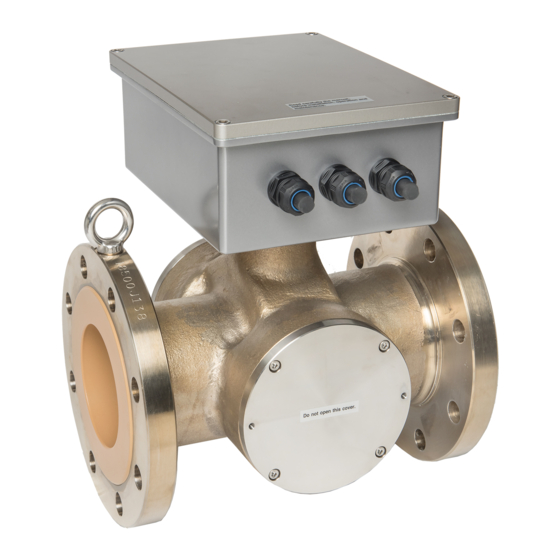
Density (Consistency) Meter LQ500
Introduction
The LQ500 density (%TS, consistency) meter uses
microwave phase shift technology to determine
concentrations of solids in the material to be measured
flowing through pipes. It can perform a stable and
realtime density (%TS, consistency) measurement
because this technology is not affected by flow velocity
along with fluid color, and also is not easily affected by
contaminants and low process pressure rate. As the
LQ500 has no moving parts, it is reliable and virtually
maintenance free.
Since the output of the LQ500 is theoretically linear, it
can be applied to a wide range of density (%TS,
consistency) measurement.
<Notice>
The LQ500 requires a full pipe to measure the
density (%TS, consistency). If certain amount of
bubbles are obviously mixed in measuring media,
there are possibilities of causing measuring error.
Contact Toshiba before installation in the
following cases:
<Possibility of unfilled condition>
(a) When it is installed at the discharge of a pump.
(b) When installation is horizontal, and unfilled
condition occurs inside the pipe.
(c) A process where the pipe becomes unfilled
when the operation is stopped.
Cable for power supply
(Detector/converter)
Figure 1. LQ500 Configuration Diagram
External Sync control
contact input
DI / DO
Density (consistency)
measurement output
AC power supply
4-20mA
Ground resistance
100 ohm or less
Cable for communication
(Detector/converter)
Figure 2. LQ500 Density (%TS, consistency)
■
Standard Configuration
• Density (%TS, Consistency) Meter: 1 set
(Detector and converter separate mounted)
• Accessories: 1 set (see Table 1 below)
Table 1. Standard Accessories
Items
Power supply
Between detector and
cable
Communication
Between detector and
cable
Fuse
(glass tube, 5.2 dia. x 20 mm)
Document
Instruction manual
Note 1: Need to prepare a power supply cable for the LQ500.
Refer to the section of cable specifications at the
overall specifications in detail.
Meter
Specifications
Quantity
converter (*1)
(32.8 ft)
converter (*1)
(32.8 ft)
2A(T), 250 V
EJL- 106J
10 m
10 m
2
1
Advertisement
Table of Contents

Related Manuals for Toshiba LQ500


Summary of Contents for Toshiba LQ500
- Page 1 Document Instruction manual (c) A process where the pipe becomes unfilled Note 1: Need to prepare a power supply cable for the LQ500. when the operation is stopped. Refer to the section of cable specifications at the overall specifications in detail.
-
Page 2: Overall Specifications
*1 TS: Total Solids <Notice> *2 Span = Upper range – Lower range 1. Install a sample tap near the LQ500 as close as *3 The material to be measured must be fluid and be filled evenly with no voids. -
Page 3: Detector Specifications
300 mm (12”) 6 mS/cm maximum suitable for use in non-hazardous location only Note 1: The LQ500 can not have an accurate density (%TS, consistency) measurement when it is over the specification according to reduce the microwave signal. Note 2: The LQ500 density (%TS, consistency) Weight: Refer to Outline Dimensions (Table 3). - Page 4 Polysulfone (*4) Applicator window sealant Fluoric rubber *1 Avoid using the LQ500 for applications where harmful liquids that cause corrosion, deterioration, or changes in quantity for the wetting materials are used. Make sure all materials at these wetting parts that are suitable for your CIP or not before cleaning.
- Page 5 Input resistance: Approx. 3k ohm opens when an error occurs in the converter or • Internal conductivity correction function: when the LQ500 is in the setting change mode, This function reduces the influence (density otherwise the contact remains closed. variation) of the conductivity changing by using •...
- Page 6 • Moving average function: Because the phase is limited from 0 degree to 360 degrees, LQ500 use the rotation N when the phase In order to keep the average density (%TS, is over 360degree. But the range of density is wide...
-
Page 7: Installation
LQ500 Installation ■ Outline Dimensions Unit: mm (inch) 250 (9.8”) 190 (7.5”) Figure 3. LQ500 detector outline dimensions Table 3. LQ500 detector outline dimensions Dimensions, Unit: mm (inch) Weight, Unit: kg (lbs) Size DIN 16 mm (inch) DIN 10 ANSI 150 JIS 10K Approx. -
Page 8: Installation Precautions
(in other words, so that the paired (13) If the density changes rapidly (less than 1second), applicator sections are placed directly side by the LQ500 may not measure accurately. The range side). of measurable density (less than 1 second) (7) This density meter does not distinguish between (c = 1.000) - Page 9 LQ500 prepare a loose mechanism in advance. (9) To minimize the impact of the bubbles, it is Note: If valve water pipe is connected to this valve, air recommended that the meter be installed on a cannot be extracted. Therefore, another valve (vent location as far as possible from the pipe outlet for valve) is needed to extract air.
-
Page 10: Wiring Precautions
(2) Ground the LQ500 with 100 ohm or less ground (8) As the cable port is made air-tight using a packing, resistance. Do not use a common ground shared by tighten the cable gland securely when all the wiring other power equipment. -
Page 11: Ordering Information
Instrument (load) The optional BF100 configurator is a software Density meter output package that you can operate the LQ500 from remote places. Please prepare the personal computer. Before you use the BF100 software package, you install the BF100 software package to the personal... - Page 12 None (Note 2) Note 1: The differences between standard type are RTD sensor and Applicator window. Note 2: Toshiba recommends to using our specified cable. ISO9001 and ISO14001 are certified. Specifications are subject to change without notice. © Toshiba Infrastructure Systems & Solutions Corporation 2019 Misuse of this product can result in damages to property or human injury.
Need help?
Do you have a question about the LQ500 and is the answer not in the manual?
Questions and answers