Salus SG888ZB System Manual
Wireless controls
Hide thumbs
Also See for SG888ZB:
- Manual (25 pages) ,
- Installation & user manual (2 pages) ,
- Pairing manual (2 pages)
Table of Contents
Advertisement
Advertisement
Table of Contents

Related Manuals for Salus SG888ZB


Summary of Contents for Salus SG888ZB
- Page 1 Wireless Controls System Guide As of September 6, 2018...
-
Page 2: Table Of Contents
System Configuration with Internet Connection using SG888ZB Gateway . . . . . . . . . . . . . . . . - Page 3 AS20WRF/BRF Thermostat – SALUS Smart Home Application · Advanced Functions & Parameters . . . . . . . . . . . . . . .
-
Page 5: Introduction
. SALUS also offers a broad ecosystem of smart home products, including connected thermostats, a smart home hub, smart plugs, water valve shutoff, and door and window sensors . A proven leader in the European market since 2003, SALUS is currently expanding across North America . -
Page 6: System Overview
By connecting the SG888ZB Gateway to your system router, the system is connected to the internet . Monitor or adjust your system from anywhere via the SALUS Smart Home remote app for iOS or Android . If the connection to the internet is lost, the system continues to function with the settings selected . - Page 7 System Overview Section 2 Download the SALUS Smart Home app on your iOS or Android device to for remote access to your SALUS controls . Apple, the Apple logo, iPhone, and iPod touch are trademarks of Apple Inc, registered in the U.S. and other countries. App Store is a service mark of Apple Inc, registered in the U.S.
-
Page 8: Salus Wireless System Components Without Internet Connection
System Overview Section 2 The AC10RF Coordinator uses Zigbee communication protocol to connect all system components, providing wireless communication easily and securely without connecting to the internet . SALUS Wireless System Components without Internet Connection AX10RF- Receiver Configured AKL01PRF-1 Zone Pump... -
Page 9: Device Installation
RF interference that will prevent it from operating correctly . SG888ZB Gateway Installation Install the SG888ZB Gateway in a central location close to a 120 VAC electrical receptical and free from radio frequency interference . If you intend to connect the system to the internet, the gateway should be close to your internet router . - Page 10 . The light will then turn red . Once an internet connection is detected (if plugged into a router) the light will turn green . Using the internet connection, the SG888ZB Gateway will try to connect with the SALUS Smart Home services . If successful, the light will turn blue . Connected to SALUS Smart Home services.
-
Page 11: Ac10Rf Coordinator Installation
4. Insert the AC10RF Coordinator into a USB port on the computer when prompted to do so AS20WRF/BRF Digital Thermostat Installation SALUS components must be set up for wireless communication with the SG888ZB Gateway or with the AC10RF Coordinator. This process, called “pairing”, should be performed with all devices installed in their intended location. - Page 12 Device Installation Section 3 AVOID Mounting the AS20 Thermostat on an exterior wall . 1 . Ensure that all required parts were included in the thermostat package: Thermostat with backplate, (4) AAA Batteries, (2) Mounting Screws, (2) Wall Anchors, Installation Instructions 2 .
-
Page 13: As20Wrf/Brf Digital Thermostat Starting Sequence
The MCU software version (example only) The Zigbee software version The Thermostat is ready to be paired (example only) The starting sequence must be complete before pairing the AS20 Thermostat with the SG888ZB Gateway or AC10RF Coordinator, and other devices. 3 .5... -
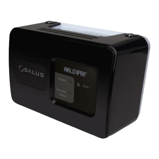
Page 14: Akl01Prf Zone Pump Wiring Center Installation
AKL01PRF Zone Pump Wiring Center Installation The AKL01PRF 1-Zone Pump Wiring Center pairs with an AS20 Wireless Thermostat via the SG888ZB Gateway or AC10RF Coordinator to provide a heat demand signal to the boiler and control a zone pump . -
Page 15: Akl04/06Prf Zone Pump Wiring Center Installation
The AKL04/06PRF Zone Pump Wiring Center pairs with an AS20WRF/BRF Wireless Thermostat via the SG888ZB Gateway or AC10RF Coordinator to provide a heat demand signal to the boiler and control a zone pump . They can control up to 6 pumps with outputs for multiple heat demands . - Page 16 Device Installation Section 3 9 . Wire each successive pump to zone pumps as needed . Each ground terminal can support 2 ground wires for convenience . 10 . 120 VAC power output is also available for a primary pump depending on the hydronic circuit design .
-
Page 17: Akl08Rf Zone Valve Wiring Center Installation
The SALUS AKL08RF Zone Valve Wiring Center connects with AS20WRF/BRF Wireless Thermostats via the AC10RF Coordinator or SG888ZB Gateway to control up to 32 actuators in 8 zones . It also provides power switching to a system circulator and a wired output for heat demand to a boiler . - Page 18 Device Installation Section 3 The boiler can be controlled wirelessly by the AKL08RF Zone Valve Wiring Center if an AX10RF Receiver, configured as RX1 (sold separately) is used with the system. However, if desired, the boiler’s thermostat input terminals (TT or RT) can be wired directly to terminals labeled “3” & “4” on the Wiring Center.
-
Page 19: Ax10Rf Receiver Installation
Device Installation Section 3 AX10RF Receiver Installation The AX10RF Receiver can be configured as a system remote boiler switch (RX1) or a single channel output to a thermal actuator or zone valve . The AX10RF Receiver must be installed by a qualified contractor. Installation and repairs are to be performed according to all national and local codes required by the authority having jurisdiction. -
Page 20: Arv10Rfm Radiator Valve Actuator Installation
ARV10RFM Radiator Valve Actuator Installation The ARV10RFM-3 Radiator Valve Actuator attaches to a Thermostatic Radiator Valve (TRV) that can connect wirelessly with your SALUS system to control room temperature . 1 . Carefully read these instructions and all instructions supplied with the unit before starting the installation . - Page 21 3 .13...
-
Page 22: Device Pairing & Setup With Internet Connection
Section 4 with Internet Connection SALUS wireless systems can be configured with an internet connection using the SG888ZB Gateway, or without an internet connection using the AC10RF Coordinator. It is important to follow the instructions that correspond to the desired configuration in the following pages. The configurations will be clearly marked, “With Internet Connection”... - Page 23 . When a message is displayed saying “Your Gateway is Up To Date” press, “Next” . Your SG888ZB Gateway will now be activated . 6 . Select the orange button on the lower part of the screen labeled, “Connect Equipment” .
-
Page 24: As20Wrf/Brf Thermostat Configuration
Device Pairing & Setup Section 4 with Internet Connection AS20WRF/BRF Thermostat Configuration Prior to pairing, the AS20WRF/BRF Thermostat should be set to the desired configuration. The default configuration for the thermostat is programmable (Pr o9) but it can also be configured as non-programmable (nP r9). - Page 25 Device Pairing & Setup Section 4 with Internet Connection The AS20WRT Thermostat can be paired with four types of devices: Display Code SALUS Model AKL01PRF – 1 Zone Pump Wiring Center AKL04PRF – 4 Zone (Default) Pump Wiring Center Note: Older firmware AKL06PRF –...
-
Page 26: As20Wrf/Brf Thermostat With Akl01/04/06Prf And Akl08Rf Wiring Centers
Wiring Center and AX10RF Receiver (if desired for boiler demand switching – RX1) . The LED ring on the SG888ZB should be solid blue . The Network Status LED on the AKL Wiring Center should be flashing and, if a AX10RF Receiver is used, the LED back light on the Auto/Manual switch should be flashing red . - Page 27 . 5 . Once the Wiring Center is connected and the LED on the SG888ZB stops flashing, press the multi button for two seconds . Zone LED on the AKL Wiring Center will illuminate indicating the ID number of the device .
- Page 28 8 . When pairing begins, the AS20WRF/BRF Thermostat 9 . When the screen reads displays at the bottom of the screen . Press it will be visible in the SALUS confirm to continue . The selection is Smart Home application . Pressing used for all of the Wiring Centers .
- Page 29 Network Status light on the AKL-RF Series Wiring Center will be solid green and, if applicable, the LED back light on the AX10RF Receiver’s Auto/Manual switch will appear solid red. The LED ring on the SG888ZB Gateway will be solid blue. 4 .8...
-
Page 30: As20Wrf/Brf Thermostat With Arv10Rfm Radiator Valve Actuator
Manual 1 2 3 4 5 6 7 Choosing the AKL Wiring Center device under the All Equipment menu on the SALUS Smart Home mobile application and pressing the Identify icon will cause the RED G1 & G2 on the device to flash . - Page 31 The SG888ZB Gateway will begin flashing red while it is searching for the devices. This will continue until the pair process is complete. The AS20 Thermostat must be set to for it to appear on the SALUS Smart Home application. COMPLETE step 3 before proceeding with pairing the ARV10RFM Radiator Actuator.
- Page 32 Device Pairing & Setup Section 4 with Internet Connection 6 . Select the Zigbee Digital 7 . Give each thermostat a 8 . Pressing the icon Control Thermostat, descriptive name that advances to thermostat checking the box . Press differentiates it from others setup .
- Page 33 Section 4 with Internet Connection 11 . From the SALUS Smart Home application, select the thermostat with which the ARV10RFM Radiator Valve Actuators are to be associated The SALUS wireless system allows up to 6 actuators to communicate with one AS20WRF/BRF thermostat.
- Page 34 Manual 1 2 3 4 5 6 7 Choosing the ARV10RFM device under the All Equipment menu on the SALUS Smart Home mobile application and pressing the Identify icon will cause the green LED on the device to flash .
-
Page 35: As20Wrf/Brf Thermostat With Ax10Rf Receiver For Boiler Switching (Rx1)
AS20WRF/BRF Thermostat and AX10RF Receiver . The LED ring on the SG888ZB Gateway should be solid blue, indicating it is connected to the internet . The switches on the cover of the Receiver should be in Auto and On positions respectively . - Page 36 Device Pairing & Setup Section 4 with Internet Connection The SG888ZB Gateway will begin flashing red while it is searching for the devices. This will continue until the pair process is complete. 2 . Use the Up arrow 3 . Then press confirm...
- Page 37 Device Pairing & Setup Section 4 with Internet Connection 6 . On the SALUS Smart Home 7 . Enter a name for both 8 . Press Finish to complete application, check the devices . Remember to name the pairing operation .
-
Page 38: As20Wrf/Brf Thermostat With Ax10Rf Receiver For Zone Valve Operation (Rx2)
Equipment All Equipment Add New Equipment Scan for Equipment The SG888ZB Gateway will begin flashing red while it is searching for the devices. This will continue until the pair process is complete. 4 .17... - Page 39 Internet Connection 2 . Use the Up arrow 3 . Then press confirm The AS20WRF/BRF to change to Thermostat on the SALUS from Smart Home application 1 2 3 4 5 6 7 4 . When Thermostat 5 . When the display shows...
- Page 40 Device Pairing & Setup Section 4 with Internet Connection 6 . On the SALUS Smart Home 7 . Enter a name for both 8 . Press Finish to complete application, check the devices . Remember to name the pairing operation .
-
Page 41: Device Pairing & Setup Without Internet
Type A Type A 2. Connect to the SALUS Update Tool (www.salusinc.com/tools.html) 3.Download and run the Update Tool by following the onscreen prompts 4. Insert the AC10RF Coordinator into a USB port on the computer when prompted to do so AS20WRF/BRF Thermostat Configuration Prior to pairing, the AS20WRF/BRF Thermostat should be set to the desired configuration. -
Page 42: As20Wrf/Brf Thermostat Withakl01/04/06Prf Or Akl08Rf Wiring Center
Device Pairing & Setup without Internet Section 5 AS20WRF/BRF Thermostat with AKL01/04/06PRF or AKL08RF Wiring Center To begin pairing, all of the required components are to be powered: AS20WRF/ BRF Thermostat, AKL Wiring Center and AX10RF Receiver configured RX1 for boiler demand (optional) . - Page 43 Device Pairing & Setup without Internet Section 5 3 . After choosing the correct thermostat 4 . When the screen reads , press confirm configuration, the AS20WRF/BRF Thermostat to proceed with the AS20WRF/BRF displays “rL AY” at the bottom of the screen . Thermostat setup .
- Page 44 Device Pairing & Setup without Internet Section 5 Record the Wiring Center zone number that flashes after pushing the pairing button to identify the wiring center. (Zone 1 = Wiring Center 1, Zone 3 = Wiring Center 3) Refer to the wiring center installation documentation for identification of wiring centers that exceed the number of zones.
-
Page 45: As20Wrf/Brf Thermostat With Arv10Rfm Radiator Valve Actuator
Device Pairing & Setup without Internet Section 5 AS20WRF/BRF Thermostat with ARV10RFM Radiator Valve Actuator Before beginning the pairing process, it is important to be sure that the ARV10RFM Radiator Valve Actuator was installed and adapted correctly as detailed in Section 3 . 1 . - Page 46 LED back light on the AX10RF Receiver’s Auto/Manual switch will appear solid red . The LED on the AC10RF Coordinator will be solid red . If the SG888ZB Gateway is used without an internet connection, the LED ring on the multi button will be solid red .
-
Page 47: As20Wrf/Brf Thermostat With Ax10Rf Receiver For Boiler Switching (Rx1)
Device Pairing & Setup without Internet Section 5 AS20WRF/BRF Thermostat with AX10RF Receiver for Boiler Switching (RX1) Be sure the switch on the inside cover of the AX10RF Receiver has been configured to RX1, for boiler demand switching, and the Receiver has been wired as indicated in Section 3, Installation . To begin pairing, all of the required components are to be powered: AS20WRF/BRF Thermostat and AX10RF Receiver . -
Page 48: As20Wrf/Brf Thermostat With Ax10Rf Receiver For Zone Valve Operation (Rx2)
Device Pairing & Setup without Internet Section 5 1 2 3 4 5 6 7 4 . When Thermostat 5 . When the display shows The AS20WRF/BRF Thermostat will displays , press , press confirm display the current temperature confirm and an icon showing the temperature mode . - Page 49 Device Pairing & Setup without Internet Section 5 1 . Press and hold the lighted red button on the AC10RF Coordinator for 5 seconds, until the LED begins flashing, to begin pairing . 2 . Use the Up arrow 3 . Then press confirm The AS20WRF/BRF to change to Thermostat join the...
-
Page 50: Resetting Factory Defaults
SALUS wireless systems can be reset to factory defaults. Resetting the SG888ZB Gateway with Internet Connection 1 . Open the SALUS Smart Home mobile application and select the drop down menu from the upper right side of the screen . -
Page 51: Resetting The Sg888Zb Gateway Without Internet Connection
To reset the SG888ZB Gateway to factory defaults without an internet connection: 1 . Press and hold the multi button on top of the SG888ZB Gateway . 2 . When the LED flashes red, release the multi button . After approximately 10 seconds, the LED ring turns solid red indicating the default values are loaded . -
Page 52: Resetting The As20Wrf/Brf Thermostat Without Internet Connection
Resetting Factory Defaults Section 6 Resetting the AS20WRF/BRF Thermostat without Internet Connection 1 2 3 4 5 6 7 1 . To reset the AS20WRF/BRF 2 . When the screen showing PS 3 . When the number 47 is Thermostat, Simultaneously, uu at the bottom appears, shown on the LCD screen, press the up arrow to... -
Page 53: Resetting The Akl01/04/06Prf Zone Pump Or Akl08Rf Zone Valve Wiring Center
The AKL Wiring Center WILL NOT OPERATE correctly until the power is cycled off and on. with Internet Connection To reset the AKL Wiring Centers, delete them from the SALUS Smart Home mobile application as follows: 1 . Select the menu from the 2 . -
Page 54: Resetting The Ax10Rf Receiver
3 . To complete the reset, cycle the power to the AX10RF Receiver off for 10 seconds . with Internet Connection To reset the AX10RF Receiver, delete the icon from the SALUS Smart Home mobile application in the same way as the Wiring Centers: 1 . -
Page 55: Resetting The Arv10Rfm Radiator Valve Actuator
Resetting Factory Defaults Section 6 Resetting the ARV10RFM Radiator Valve Actuator without Internet Connection 1 . Press and hold all three buttons on the ARV10RFM Valve Actuator for 30 seconds . The light will flash amber . 2 . Open the battery compartment and remove one of the batteries . 3 . -
Page 56: Setting Device Parameters
Setting Device Parameters Section 7 AS20WRF/BRF Thermostat User Interface Key 1 ON OFF 1 2 3 4 5 6 7 1 2 3 4 5 6 7 Icon Function Icon Function Floor sensor is connected, flashes when high limit is Indicates active heating mode . -
Page 57: As20Wrf/Brf Thermostat - Installer Parameter Setup
Section 7 AS20WRF/BRF Thermostat – Installer Parameter Setup Installers can set up the AS20WRF/BRF parameters using the SALUS Smart Home application if an SG888ZB Gateway is used and connected to the internet. Alternatively, the parameters can be entered directly on the AS20WRF/BRF Thermostat. -
Page 58: As20Wrf/Brf Thermostat - Functions & Parameters
Setting Device Parameters Section 7 AS20WRF/BRF Thermostat – Functions & Parameters Parameters Function Description Default Value SI Metric Units - °C Select Units US Customary Units - °F Time Proportional & Integral (TPI) Heating Control ON/OFF – 0 .5°C (1 .0°F) Increments ON/OFF –... -
Page 59: As20Wrf/Brf Thermostat - Setting The Time
Section 7 AS20WRF/BRF Thermostat – Setting the Time The time can be set directly on the AS20WRF/BRF User Interface or on the SALUS Smart Home application, provided a SG888ZB Gateway is used and connected to the internet. 1 2 3 4 5 6 7 1 2 3 4 5 6 7 1 . -
Page 60: As20Wrf/Brf Thermostat - Setting The Temperature
Setting Device Parameters Section 7 AS20WRF/BRF Thermostat – Setting the Temperature The AS20WRF/BRF Thermostat comes pre-programmed with a default setback schedule for weekdays and weekends. The instructions that follow the graphical representation of these schedules allow the installer to choose the target temperatures for each of these periods. Default Weekday Schedule Heating Mode Default Temp. -
Page 61: As20Wrf/Brf Thermostat - Schedule Set Up
Changing the default schedule for the AS20WRF/BRF Thermostat can be done directly from the User Interface or from the SALUS Smart Home mobile application, if an SG888ZB Gateway is used and connected to the internet. Graphical representations of the default schedules are on the previous page. Use the following graphs to plan schedule updates. - Page 62 Setting Device Parameters Section 7 1 2 3 4 5 6 7 2 . When the screen flashes 1 . Press & hold the confirm with displayed, press button to access the schedule program . confirm 3 . Use the right/left &...
- Page 63 Setting Device Parameters Section 7 1 2 3 4 5 6 7 1 2 3 4 5 6 7 1 2 3 4 5 6 7 4 . Use & 5 . Use & 6 . Use & to choose to set the hour for the to set the minutes for the the icon corresponding to...
-
Page 64: As20Wrf/Brf Thermostat - Temporary Override
Setting Device Parameters Section 7 AS20WRF/BRF Thermostat – Temporary Override 1 2 3 4 5 6 7 1 2 3 4 5 6 7 1 2 3 4 5 6 7 1 . Use the & icon will show next 2 . -
Page 65: As20Wrf/Brf Thermostat - Parameter Setup With Internet Connection
AS20WRF/BRF Thermostat – Parameter Setup with Internet Connection If the SG888ZB Gateway is used and is connected to the internet, the SALUS Smart Home application can be used to set up the parameters. Alternatively, the parameters can be entered directly on the AS20WRF/BRF Thermostat. -
Page 66: As20Wrf/Brf Thermostat - Salus Smart Home Application - Functions & Parameters
The following are a list of functions and parameters that can be accessed without the password. To access more parameters the password must be entered. Instructions for entering the password to access more parameters follow. AS20WRF/BRF Thermostat – SALUS Smart Home Application - Functions & Parameters Parameters... -
Page 67: As20Wrf/Brf Thermostat - Salus Smart Home Application - Advanced Functions & Parameters
Setting Device Parameters Section 7 AS20WRF/BRF Thermostat – SALUS Smart Home Application - Advanced Functions & Parameters Parameters Function Description Default Value Time Proportional & Integral (TPI) Heating Control ± 1 .0°F [± 0 .5°C] ± 0 .50°F [± 0 .25°C] ON/OFF –... -
Page 68: As20Wrf/Brf Thermostat - Schedule Setup With Internet Connection
AS20WRF/BRF Thermostat – Schedule Setup with Internet Connection The following instructions are provided to set up the thermostat temperature schedule using the SALUS Smart Home Application. 1 . Select the thermostat icon 2 . Press the thermostat name 3 . Press the settings “gear” icon on the screen . - Page 69 Setting Device Parameters Section 7 7 . Edit temperatures and/or 8 . Repeat the process for 9 . Your AS20WRF/BRF interval times to optimize Sa – Su to create a Thermostat is now set up . the heating schedule . Press weekend schedule .
-
Page 70: Troubleshooting
Error Code Description Troubleshooting Steps SG888ZB Gateway Is the gateway powered with either red or blue solid LED? Communication link failure AC10RF Coordinator Is the coordinator powered with solid red LED? •... - Page 71 Troubleshooting Section 8 Error Code Description Troubleshooting Steps Not Used Call Technical Helpline (855) 557-2587 Check to be sure that the wiring center is powered, and the network status light is on . AX10RF (RX1) Receiver lost link - If the network status light is flashing, perform the with Wiring Center pairing procedure listed in section 4 .
- Page 72 Appendix A A .1...
- Page 73 Appendix A A .2...
- Page 74 Appendix A A .3...
- Page 75 Appendix A A .4...
- Page 76 Appendix A A .5...
Need help?
Do you have a question about the SG888ZB and is the answer not in the manual?
Questions and answers