Festo CPV..-DI01 series Electronic Manual
Valve terminal with direct connection
Hide thumbs
Also See for CPV..-DI01 series:
- Manual (200 pages) ,
- User instructions (62 pages) ,
- Brief description (12 pages)

Related Manuals for Festo CPV..-DI01 series


Summary of Contents for Festo CPV..-DI01 series
- Page 1 Compact Performance Electronics manual CPV valve terminal with direct connection Type CPV..−DI01 Field bus protocols: − PROFIBUS−DP − Festo field bus − ABB CS31 − SUCOnet K Manual 165 817 en 0503d...
- Page 3 ....... . . 165 817 E (Festo AG & Co. KG, D 73726 Esslingen, Federal Republic of Germany, 2003) Internet: http://www.festo.com...
- Page 4 Contents and general instructions Festo P.BE−CP−DI01−EN en 0503d...
-
Page 5: Table Of Contents
Configuration with a Siemens master ....... 2−10 Festo P.BE−CP−DI01−EN en 0503d... - Page 6 3−26 Commissioning Festo field bus ........
- Page 7 ..... . . 8−4 CP system extension and number of inputs/outputs ....8−6 Festo P.BE−CP−DI01−EN en 0503d...
- Page 8 ............B−3 Festo P.BE−CP−DI01−EN en 0503d...
-
Page 9: Designated Use
Please comply with national and local safety laws and regula tions. If you wish to implement an emergency stop function, please observe the measures listed in section 1.6.3. Festo P.BE−CP−DI01−EN en 0503d... -
Page 10: Target Group
This manual is intended exclusively for technicians trained in control and automation technology, who have experience in installing, commissioning, programming and diagnosing slaves on the field busesnamed above. Service Please consult your local Festo repair service if you have any technical problems. VIII Festo P.BE−CP−DI01−EN en 0503d... -
Page 11: Notes On The Use Of This Manual
This manual describes the functionality of the software version as from 1.x and the hardware version as from 04/98 of the CPV valve terminal with direct connection for PROFIBUS−DP, Festo field bus, ABB CS31, Moeller SUCOnet K. This manual contains specific information on installing, com missioning, programming and diagnosing CPV valve terminals with direct connection for the field buses named. -
Page 12: Important User Instructions
This means that failure to observe this instruction may result in damage to property. The following pictogram marks passages in the text which describe activities with electrostatically sensitive compo nents. Electrostatically sensitive components may be damaged if they are not handled correctly. Festo P.BE−CP−DI01−EN en 0503d... - Page 13 Accessories: Information on necessary or sensible accessories for the Festo product. Environment: Information on environment−friendly use of Festo products. Text markings The bullet indicates activities which may be carried out in · any order. 1. Figures denote activities which must be carried out in the numerical order specified.
- Page 14 (CP input modules and CP output modules) I/Os Digital inputs and outputs Digital output Output byte Octet Number of address words assigned by the CP system PLC/IPC Programmable logic controller/industrial PC Tab. 0/1: Product−specific terms and abbreviations Festo P.BE−CP−DI01−EN en 0503d...
-
Page 15: Installation
Installation Chapter 1 1−1 Festo P.BE−CP−DI01−EN en 0503d... - Page 16 ......... 1−37 Use in an explosion−protected environment ......1−40 1−2 Festo P.BE−CP−DI01−EN en 0503d...
-
Page 17: General Instructions On Installation
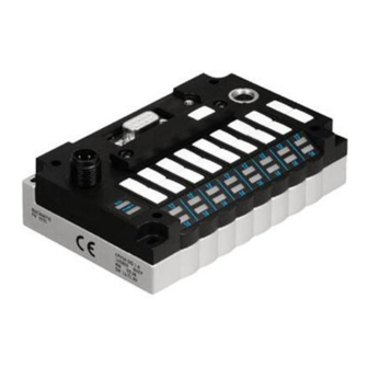
The CPV valve terminal with field bus direct connection (CPV Direct) contains electrostatically sensitive compo nents. Do not therefore touch any contacts. Observe the regulations for handling electrostatically sensitive components. You will then prevent the electronics from being damaged. 1−3 Festo P.BE−CP−DI01−EN en 0503d... - Page 18 CP extension connection Operating voltage connection for Switching status displays of the electronics/load voltage connection CP valve coils (yellow LEDs) for CP valves (4−pin M12 plug) Fig. 1/1: Connecting and display elements of the CPV Direct 1−4 Festo P.BE−CP−DI01−EN en 0503d...
-
Page 19: Configuring The Cpv Direct
The switch module contains electrostatically sensitive com ponents. Do not therefore touch any contacts. Observe the regulations for handling electrostatically sensitive components. The switch module must be removed before the CPV Direct can be set. Fig. 1/2: Fitting/removing the switch module 1−5 Festo P.BE−CP−DI01−EN en 0503d... - Page 20 2. Tighten the two fastening screws alternately. Please note Do not tilt the switch module when fitting it. The fitting position is clearly marked by a groove in the housing. Make sure that the seal is seated correctly. 1−6 Festo P.BE−CP−DI01−EN en 0503d...
-
Page 21: Setting The Cpv Direct
5. Assign an unused station number to the CPV Direct. Set the desired station number (8−position DIL switch, elements 1...7). 6. Set the diagnostic mode (8−position DIL switch, element 8). 7. Fit the switch module (see chapter 1.2.1). 1−7 Festo P.BE−CP−DI01−EN en 0503d... - Page 22 DIL 1: OFF, DIL 2: OFF DIL 1: ON, DIL 2: ON DIL 1: ON, DIL 2: OFF DIL 1: OFF, DIL 2: ON Tab. 1/1: Setting the field bus protocol with the 4−position DIL switch 1−8 Festo P.BE−CP−DI01−EN en 0503d...
- Page 23 Setting: Extension of the CP system with 4−position DIL switch Please note Depending on the extension set, the CP system occupies a different number of inputs and outputs or station numbers. Further information can be found in chapter 1.7. 1−9 Festo P.BE−CP−DI01−EN en 0503d...
- Page 24 2; ...; 98 SUCOnet K Tab. 1/3: Permitted station numbers for the different field buses Recommendation: Assign the station numbers in ascending order. Assign the station numbers to suit the machine structure of your system. 1−10 Festo P.BE−CP−DI01−EN en 0503d...
- Page 25 The station number is entered coded with the 8−position DIL switch. Set station number: 5 Set station number: 38 = 1 + 4 = 5 = 2 + 4 + 32 = 38 Tab. 1/4: Examples of set station numbers (binary coded) 1−11 Festo P.BE−CP−DI01−EN en 0503d...
- Page 26 DIL switch elements 1...6 suffice for setting the station number. With protocol ABB CS31, switch element 7 must be set to OFF. With the Festo field bus, switch elements 7 and 8 are used for setting the baud rate. 1−12 Festo P.BE−CP−DI01−EN en 0503d...
- Page 27 1. Installation Stat. Stat. Reserved Tab. 1/5: Setting station numbers 0...31: Position of the DIL switch elements 1−13 Festo P.BE−CP−DI01−EN en 0503d...
- Page 28 1. Installation Stat. Stat. Tab. 1/6: Setting station numbers 32...63: Position of the DIL switch elements 1−14 Festo P.BE−CP−DI01−EN en 0503d...
- Page 29 1. Installation Stat. Stat. Tab. 1/7: Setting station numbers 64...95: Position of the DIL switch elements 1−15 Festo P.BE−CP−DI01−EN en 0503d...
- Page 30 1. Installation Stat. Stat. Tab. 1/8: Setting station numbers 96...125: Position of the DIL switch elements 1−16 Festo P.BE−CP−DI01−EN en 0503d...
- Page 31 If the device−related diagnosis is deactivated (switch element 8 to OFF), no device−related diagnostic information will be sent from the valve terminal to the master system, e.g. short circuit at the outputs or undervoltage of the valves (see sec tion 3.3). 1−17 Festo P.BE−CP−DI01−EN en 0503d...
-
Page 32: Setting The Field Bus Baud Rate
1. Installation Setting the field bus baud rate Please note It is only necessary to set the baud rate with the Festo field bus protocol. The CPV Direct automatically recognizes the baud rate for the PROFIBUS−DP (9.2 kBd ... 12 MBd) and the SUCOnet K (187.5 kBd ... -
Page 33: Connecting The Field Bus
If the valve terminal is fitted onto the moving part of a ma chine, the field bus cable on the moving part must be pro vided with strain relief. Please observe also the relevant regulations in IEC/DIN EN 60204−1. 1−19 Festo P.BE−CP−DI01−EN en 0503d... - Page 34 Exact specifications on the bus length can be found in the next section and in the manuals for your control system. Festo field bus / ABB CS31 / Moeller SUCOnet K Refer to the PLC manual for your controller for the type of cable to be used.
-
Page 35: Field Bus Baud Rate And Field Bus Length For Profibus−Dp
100 m 187.5 1000 m 33.3 m 400 m 20 m 1500 200 m 6.6 m 3000...12000 100 m Tab. 1/10: Max. field bus length and branch line length for PROFIBUS−DP depending on the baud rate 1−21 Festo P.BE−CP−DI01−EN en 0503d... -
Page 36: Field Bus Interface
You can connect the CPV valve terminal with the field bus plug from Festo type FBS−SUB−9−GS−DP−B. Please note Only the Festo field bus plug complies with IP65. Before connecting field bus plugs from other manufacturers: replace the two flat screws by bolts (part no. 340960). - Page 37 (View of socket of the CPV Direct) Type FBS−SUB−9−GS−DP−B (part no. 532216) Pin numbers of the SUCOnet K interface Tab. 1/12: Pin assignment of the field bus interface for Festo field bus, ABB CS13 and SUCOnet K 1−23 Festo P.BE−CP−DI01−EN en 0503d...
-
Page 38: Connection Possibilities
Clamp strap for screening/shield connection Field bus incoming (IN) Switch for bus termination and continuing field Field bus continuing (OUT) Only connected capacitively Fig. 1/6: Field bus plug from Festo, type FBS−SUB−9−GS−DP−B 1−24 Festo P.BE−CP−DI01−EN en 0503d... - Page 39 1. Installation Please note The clamp strap in the field bus plug from Festo is con nected internally only capacitively with the metallic hous ing of the sub−D plug. This is to prevent equalizing currents flowing through the screening of the field bus cable.
- Page 40 5. FE: Functional earth Housing/thread: Screening/shield Bus out Bus in Protective cap or plug with bus termination resistor if connection is not used. Tab. 1/13: Pin assignment of the field bus interface with adapter for M12 connection, 5−pin 1−26 Festo P.BE−CP−DI01−EN en 0503d...
- Page 41 Siemens Optical Link Module (OLM) for PROFIBUS plus Siemens Optical Link Plug (OLM) for PROFIBUS (IP20) ® Harting Han−InduNet Media converter IP65 in combina tion with adapter cable for Festo products (optical data transmission in DESINA installation concept). 1−27 Festo P.BE−CP−DI01−EN en 0503d...
-
Page 42: Bus Termination With Terminating Resistors
Fit a bus termination to both ends of a bus segment. · Recommendation: Use the ready−to−use field bus plugs from Festo for the bus termination. A suitable resistor network is incorporated in the housing of this plug (see Fig. 1/7). -
Page 43: Connecting The Power Supply
The connection for the power supply is in the form of a plug. The pin assignment of the plug can be found on the following pages. For connecting the power supply, use plugs from the Festo range which correspond to the outer diameter of the cable used (see Appendix A.3). - Page 44 4. Connect the conductors. 5. Replace the connecting part on the housing of the socket and screw it tight. Pull the cable back so that there are no loops inside the housing. 6. Tighten the strain relief. 1−30 Festo P.BE−CP−DI01−EN en 0503d...
-
Page 45: Selecting The Power Unit
CP modules and valve coils. Recommendation: Used closed−loop power units. · When selecting the power units, check that they provide · sufficient output. Ascertain here the total current con sumption according to the following table. 1−31 Festo P.BE−CP−DI01−EN en 0503d... - Page 46 Current consumption of all simultaneously energized valve coils __x_____mA =_______mA Current consumption depends on the valve type (see Technical specifications for the valves in the relevant pneumatics manuals). Tab. 1/14: Calculating the total current consumption 1−32 Festo P.BE−CP−DI01−EN en 0503d...
-
Page 47: Connecting The Power Supply
Protect the load voltage of the CPV valve coils with an external fuse max. 2 A. In this way you can avoid functional damage to the CPV Direct in the event of a short circuit. 1−33 Festo P.BE−CP−DI01−EN en 0503d... - Page 48 Register the fact that the load voltage is switched off by means of an input signal in the controller. Block the control signal of the valves by locking the out put signal with the input signal load voltage." 1−34 Festo P.BE−CP−DI01−EN en 0503d...
- Page 49 3: 0 V 4: Earth/ground connection Fig. 1/9: Pin assignment of power supply connection Potential equalization The CPV valve terminal has two earth connections for poten tial equalization: on the power supply connection on the end plate. 1−35 Festo P.BE−CP−DI01−EN en 0503d...
- Page 50 3 1 2 4 24 V Potential equalization Load voltage can be switched off separately The earth connection at pin 4 is designed for 3 A Fig. 1/10: Example of connection with PELV power unit and potential equalization 1−36 Festo P.BE−CP−DI01−EN en 0503d...
-
Page 51: Extending The Cpv Direct
CP system. Modules which you connect to the CP extension connec tion will be recognized only if the DIL switch is set cor rectly. Information on setting the DIL switches can be found in chapter 1.2.2. 1−37 Festo P.BE−CP−DI01−EN en 0503d... - Page 52 The CP connecting cables must have special electrical characteristics. Always use, therefore, Festo CP connecting cables. You can obtain ready−to−use CP connecting cables from Festo. These are available in various lengths and types. You will find a summary in Appendix A.
- Page 53 CP input module 16 inputs (8 x M12 plug, 16 x M8 plug) CP output module with 8 outputs (8 x M12 plug) CPV or CPA valve terminal Tab. 1/15: Extension possibilities for the CPV Direct 1−39 Festo P.BE−CP−DI01−EN en 0503d...
-
Page 54: Use In An Explosion−Protected Environment
1. Set the DIL switches and close the switch covers again. Make sure that the seals are seated correctly. 2. Install the product. CP cables and CP plugs from Festo are regarded as accessories within the framework of the con formity test as per 94/9/EG and may be used in poten tially explosive environments, in accordance with the Ex−... -
Page 55: Commissioning Profibus−Dp
Commissioning PROFIBUS−DP Chapter 2 2−1 Festo P.BE−CP−DI01−EN en 0503d... - Page 56 ........2−16 2.3.3 Commissioning the CP system on the PROFIBUS−DP ... 2−17 2−2 Festo P.BE−CP−DI01−EN en 0503d...
-
Page 57: Preparing The Cpv Direct For Commissioning
If there is a separate supply for the control system and for the field bus slaves, the power should be switched on in the fol lowing sequence: 1. the power supply for all the field bus slaves. 2. the power supply for the controller. 2−3 Festo P.BE−CP−DI01−EN en 0503d... -
Page 58: Address Assignment Of The Cpv Direct
If a valve location is fitted with a double−solenoid valve, the following assignment applies: pilot solenoid 14 occupies the lower−value address pilot solenoid 12 occupies the higher−value address. With single−solenoid valves the higher−value address remains unused. 2−4 Festo P.BE−CP−DI01−EN en 0503d... - Page 59 Direct and from the front to the rear on the individual valve locations. POWER OB x OB x+1 OB: Output byte Fig. 2/2: Address assignment of the CPV Direct (outputs) with examples for OB20 and OB21 2−5 Festo P.BE−CP−DI01−EN en 0503d...
-
Page 60: Information On Commissioning
All the inputs of the CP system will be frozen." The valve terminal now no longer reacts to modifications to the output image in the master. With each further SYNC command, the updated output image will be transmitted. Return to normal operation: UNFREEZE command 2−6 Festo P.BE−CP−DI01−EN en 0503d... - Page 61 The position of the DIL switch for the extension of the CP system is relevant for the required DP identifiers (see sections 1.2.2 and 1.7). Please note Make sure that the DIL switches are set according to the extension of your CP system. 2−7 Festo P.BE−CP−DI01−EN en 0503d...
- Page 62 Enter the identifiers corresponding to the physical se quence of the modules, starting with the CPV Direct. Example: DP identifier Comment 16DO 16 digital outputs (CPV Direct) 16DI 16 digital inputs (input module) Tab. 2/2: CPV Direct extended with one input module 2−8 Festo P.BE−CP−DI01−EN en 0503d...
-
Page 63: Device Master File (Gsd) And Icon Files
(Ident. number, Revision, etc.), the device master file (GSD) also contains a selection of identifiers. Reference sources Current GSD files can be found on the Festo Internet pages under: www.festo.com/fieldbus You can obtain the GSD files and further configuration aids with the CD ROM Utilities"... -
Page 64: Configuration With A Siemens Master
(e. g. with Windows Explorer) or loaded via the menu [Options] [Install new GSD]. Please note Update the hardware catalogue, if you copy the GSD during work with STEP 7. Menu HW Config: [Options] [Update catalogue] 2−10 Festo P.BE−CP−DI01−EN en 0503d... - Page 65 4. Insert a DP master system: Right−hand mouse click on DP" under CPU" in the rack Click on [Add master system] in the context menu. The line of the DP master system will be displayed. 2−11 Festo P.BE−CP−DI01−EN en 0503d...
- Page 66 \PROFIBUS−DP\Additional Field Devices\Valves." The folder VALVES is displayed when you copy the GSD (see step 1 of the preparations). Pull the station type FESTO CPV DO01" onto the line of the DP master system 2. The dialogue window Properties PROFIBUS interface"...
- Page 67 2. Commissioning PROFIBUS−DP Fig. 2/3: Station selection with STEP 7 HW Config (The windows displayed are not all visible at the same time, see text.) 2−13 Festo P.BE−CP−DI01−EN en 0503d...
- Page 68 1. Click on the icon of the valve terminal to be configured in HW Config 1. The configuration table will be displayed under the rack 2. 2. Open the module FESTO CPV DI01" (Folder\PROFIBUS− DP\Additional Field Devices\Valves\...) in the hardware catalogue 3.
- Page 69 2. Commissioning PROFIBUS−DP Fig. 2/4: Configuration with STEP 7 V HW Config (Example for extension with one CP input module, explanations see text.) This concludes the station selection and configuration. 2−15 Festo P.BE−CP−DI01−EN en 0503d...
-
Page 70: Example Of Addressing
CPV Direct CPV valve terminal with 8 valve plates CP input module with 16 inputs O20.0...O21.7 O22.0...O23.7 I20.0...I21.7 Fig. 2/5: Example addressing the inputs and outputs of a CP system with CPV Direct and maximum extension 2−16 Festo P.BE−CP−DI01−EN en 0503d... -
Page 71: Commissioning The Cp System On The Profibus−Dp
NOMINAL configuration are com plete and correct (see also section 2.1.2). the power supply for the programmable logic controller and for the field bus slaves is switched on eithersimulta neously or in the sequence indicated above. 2−17 Festo P.BE−CP−DI01−EN en 0503d... - Page 72 Please note A CP valve location occupies two addresses. The following assignment applies: lower value address: pilot solenoid 14 higher−value address: pilot solenoid 12 2−18 Festo P.BE−CP−DI01−EN en 0503d...
-
Page 73: Diagnosis Profibus−Dp
Diagnosis PROFIBUS−DP Chapter 3 3−1 Festo P.BE−CP−DI01−EN en 0503d... - Page 74 3−24 3.6.2 Sensor supply at an input module ......3−26 3−2 Festo P.BE−CP−DI01−EN en 0503d...
-
Page 75: Diagnosis By Means Of Leds
3.1.1 Normal operating status In normal operating status the green power LED lights up. lights up; flashes; Colour Operating status Fault treatment Normal None POWER green lights up Normal None Tab. 3/1: Normal operating status 3−3 Festo P.BE−CP−DI01−EN en 0503d... -
Page 76: Diagnosis Profibus
Load voltage faults are always displayed with the green LED (irrespective of the diagnostic mode set). If the device−related diagnosis is active, faults will also be passed on to the master PLC via the field bus. 3−4 Festo P.BE−CP−DI01−EN en 0503d... - Page 77 Switch module is missing Install switch module · briefly out Switch module defective Replace switch module · Tab. 3/3: Fault diagnosis with the red BUS LED 3−5 Festo P.BE−CP−DI01−EN en 0503d...
-
Page 78: Leds For Status Display Of The Valve Solenoid Coils
Tab. 3/4: LEDs for status display of the valve solenoid coils Please note If there is no valve solenoid coil, the assigned LED will not show control of the output. 3−6 Festo P.BE−CP−DI01−EN en 0503d... -
Page 79: Eliminating Faults
Extension greater System starts. than the setting in Carry out device− < the switch module. related diagnosis (see section 3.3). Tab. 3/5: Behaviour if the system extension differs from the setting of the DIL switch 3−7 Festo P.BE−CP−DI01−EN en 0503d... -
Page 80: Diagnosis Via Profibus−Dp
Short circuit in sensor power supply Failure of load voltage at the output modules Short circuit/overload at the output modules Interruption of the CP connection on various CP modules Lower voltage tolerance limit of CP valves exceeded (< 20.4 V) 3−8 Festo P.BE−CP−DI01−EN en 0503d... -
Page 81: Diagnostic Steps
CPV Direct is without power or the bus plug is not inserted. Planned extension of the CP system does not correspond to the extension set in the switch module (see sections 3.2 and 1.7). Fig. 3/2: First diagnostic step 3−9 Festo P.BE−CP−DI01−EN en 0503d... - Page 82 It can in some cases be helpful if you switch off the device− related diagnosis when commissioning your system. If your controller does not start, try at first with the setting Device− related diagnosis inactive" in the switch module (see section 1.2.2). 3−10 Festo P.BE−CP−DI01−EN en 0503d...
-
Page 83: Overview Of Diagnostic Bytes
3.3.3 Overview of diagnostic bytes Diagnostic words Several diagnostic words are provided for each bus slave. The diagnostic words and their meaning for CP systems from Festo are shown in the following table: Byte Octet Diagnostic address Diagnostic address + 1 Octet... -
Page 84: Details Of Standard Diagnostic Information
1 = CP system does not support the function requested Diag.Invalid_Slave_Response Always 0 (set by CP system) Diag.Prm_Fault Last parametrizing telegram faulty Diag.Master_Lock Always 0 (set by CP system) bold = Valve terminal related bits Tab. 3/7: Diagnostic bits station status1 3−12 Festo P.BE−CP−DI01−EN en 0503d... - Page 85 = Valve terminal related bits Tab. 3/8: Diagnostic bits of station status 2 Octet 3: Station status_3 Meaning Explanation 0...6 Reserved Diag.Ext_Diag_Overflow Always 0 (set by CP system) Tab. 3/9: Diagnostic bits of station status 3 3−13 Festo P.BE−CP−DI01−EN en 0503d...
- Page 86 4 octets Device−related diagnosis" incl. the header octet, are made available/transferred, irre spective of the equipment fitted on the CP system. 3 of the 4 octets are used. Tab. 3/10: Overview of the octets 4...7 3−14 Festo P.BE−CP−DI01−EN en 0503d...
- Page 87 1 = Fault CP string/CP valve terminal Not used Not used Not used Is sent to the master controller only if the device−related diagnosis is activated in the switch module. Tab. 3/11: Diagnostic bits device−related diagnosis 1 3−15 Festo P.BE−CP−DI01−EN en 0503d...
- Page 88 1 = Short circuit/overload in sensor supply < 10 V 1 = Load voltage of valve coils < 20.4 V 1 = Load voltage of valve coils < 10 V load Not used Tab. 3/12: Diagnostic bits device−related diagnosis 2 3−16 Festo P.BE−CP−DI01−EN en 0503d...
-
Page 89: Fault Treatment
PLC stop, field bus interruption or field bus fault: Single−solenoid valves move to the basic position. Double−solenoid valves remain in the current position. Mid−position valves move to the mid−position (depend ing on valve type: pressurized, exhausted or blocked). 3−17 Festo P.BE−CP−DI01−EN en 0503d... -
Page 90: Siemens Simatic S5/S7
OM is programmed QVZ: Quitting delay, OM: Organisation module, PEU: Periphery not clear Tab. 3/13: Fault reactions STOP and RUN with S5/S7 Further details on response monitoring can be found in the relevant controller manuals. 3−18 Festo P.BE−CP−DI01−EN en 0503d... - Page 91 (see window Properties DP slave" in HW Config) RET_VAL:=MW100 If fault occurs, output fault code RECORD:=P#M110.0 WORD 5 Pointer at start of data range for diagnosis and length of diagnostic data BUSY:=M10.0 Reading concluded Fig. 3/4: Example 3−19 Festo P.BE−CP−DI01−EN en 0503d...
-
Page 92: Online Diagnosis With Step 7
3. 4. Select the register Diagnostic Buffer" 4. 5. Click on the event and read the details 5. These supply more detailed information on further procedures and de pend on the S7 controller used. 3−20 Festo P.BE−CP−DI01−EN en 0503d... - Page 93 3. Diagnosis PROFIBUS−DP Fig. 3/5: Online diagnosis via diagnostic buffer (explanation see text) 3−21 Festo P.BE−CP−DI01−EN en 0503d...
-
Page 94: Device−Related Diagnosis With Step 7 (Up To V 5.2)
1. Click with the right−hand mouse key on the icon of the valve terminal 1. 2. Click on [Module Information ...] in the context menu which now appears. The window Module Information" will be shown. 3. Read the diagnostic information 2. 3−22 Festo P.BE−CP−DI01−EN en 0503d... - Page 95 3. Diagnosis PROFIBUS−DP Fig. 3/6: Device−related diagnosis with STEP 7 (explanation see text) 3−23 Festo P.BE−CP−DI01−EN en 0503d...
-
Page 96: Short Circuit/Overload
9 Device−related diagnosis 2" will be set to logical 1. Please note The outputs cannot be used again until the short circuit or overload has been eliminated and the fault deleted. 3−24 Festo P.BE−CP−DI01−EN en 0503d... - Page 97 All outputs of the CP system will be reset · CP system automatically Tab. 3/15: Deleting the fault possibilities The outputs can then be used again. If the short circuit/over load still exists, the outputs will be switched off again. 3−25 Festo P.BE−CP−DI01−EN en 0503d...
-
Page 98: Sensor Supply At An Input Module
The inputs can then be scanned again. If the short circuit/ overload still exists, the fault will be shown again. Module CP−E16−M8−Z: The short circuit/overload will be reset automatically and the voltage will be switched on again. 3−26 Festo P.BE−CP−DI01−EN en 0503d... -
Page 99: Commissioning Festo Field Bus
Commissioning Festo field bus Chapter 4 4−1 Festo P.BE−CP−DI01−EN en 0503d... - Page 100 4. Commissioning Festo field bus Contents Commissioning Festo field bus ........
-
Page 101: Preparing The Cpv Direct For Commissioning
4. Commissioning Festo field bus Preparing the CPV Direct for commissioning 4.1.1 Switching on the operating voltages Please note Please observe also the switching−on instructions in the manual for your controller. When the controller is switched on, it automatically carries out a comparison between the NOMINAL and the ACTUAL configurations. -
Page 102: Address Assignment Of The Cpv Direct
4. Commissioning Festo field bus 4.1.2 Address assignment of the CPV Direct The CPV Direct always occupies 16 output addresses, irre spective of the number of valve solenoid coils fitted on it. This enables the CPV Direct to be extended at a later stage with out the need to shift the addresses. - Page 103 4. Commissioning Festo field bus Addresses are assigned from left to right on the CPV Direct and from the front to the rear on the individual valve locations. POWER OWn.x OWn.x+1 OW: Output word Slave number Word (8 bits) Fig. 4/2: Address assignment of the CPV Direct (outputs) with example for slave no.
-
Page 104: Configuration
4. Commissioning Festo field bus Configuration Please note The CP modules occupy constantly 16 outputs or 16 in puts, irrespective of the system extension and the type of module (inputs, outputs, valves). The position of the DIL switch for the extension of the CP sys tem is relevant for the number of assigned I/O addresses and station numbers (see sections 1.2.2 and 1.7). -
Page 105: Configuration With Field Bus Configurator
Enter two IW or two OW for each module (16 inputs or 16 outputs). Please note With a Festo field bus master you can also configure the CP system with an actual−nominal comparison. An existing field bus configuration will then be loaded into the master. - Page 106 4. Commissioning Festo field bus Fig. 4/3: Example configuring with FST 200; select CP system from slave list Fig. 4/4: Example configuring with FST 200; enter number of IW or OW 4−8 Festo P.BE−CP−DI01−EN en 0503d...
- Page 107 4. Commissioning Festo field bus Addressing Please note Addressing the CP system via the Festo field bus is carried out in bytes. Note the differences from the word−by−word addressing of other field bus slaves. Addressing the The following example shows the addressing of the inputs/...
- Page 108 4. Commissioning Festo field bus 4−10 Festo P.BE−CP−DI01−EN en 0503d...
-
Page 109: Diagnosis Festo Field Bus
Diagnosis Festo field bus Chapter 5 5−1 Festo P.BE−CP−DI01−EN en 0503d... - Page 110 5. Diagnosis Festo field bus Contents Diagnosis Festo field bus ........
-
Page 111: Diagnosis With Leds
5. Diagnosis Festo field bus Diagnosis with LEDs The LEDs on the cover indicate the operating status of the CPV Direct. Red LED: Bus status/fault (BUS) Green LED: Operating voltage display (POWER) Yellow LED POWER row for pilot solenoid 12... -
Page 112: Fault Displays Of The Bus/Power Leds
5. Diagnosis Festo field bus 5.1.2 Fault displays of the BUS/POWER LEDs Fault diagnosis with the green LED (POWER) Colour Operating status Fault treatment POWER Operating voltage for electronics Check the operating voltage · not applied supply (pin 1) POWER... - Page 113 5. Diagnosis Festo field bus Fault diagnosis with the red LED (BUS) Colour Operating status Fault treatment Hardware fault Servicing required · lights up Field bus address not permitted Correct address setting · flashes fast (0, ..., 63) Field bus connection not OK.
-
Page 114: Leds For Status Display Of The Valve Solenoid Coils
5. Diagnosis Festo field bus 5.1.3 LEDs for status display of the valve solenoid coils There is a yellow LED for every valve solenoid coil (see Fig. 5/1). This LED indicates the switching status of the valve solenoid coil. Colour... -
Page 115: Diagnosis Via The Field Bus
Diagnosis via the field bus All diagnostic information can be evaluated directly with a Festo PLC. For this purpose a fault list is created in the master. All diagnostic bits are included in this fault list and are contin ually updated. -
Page 116: Fault Treatment
5. Diagnosis Festo field bus Fault treatment 5.3.1 Reaction of the CPV Direct to faults Reaction to faults in the control system: The CP valves and any electric outputs will be switched off in the event of faults after the following times: Baud rate (kBaud) Switch−off time... -
Page 117: Short Circuit/Overload At An Output Module
5. Diagnosis Festo field bus 5.3.2 Short circuit/overload at an output module In the event of a short circuit or overload: all the digital outputs of the module will be switched off. the green LED Diag" on the output module will flash quickly. -
Page 118: Short Circuit In The Sensor Supply At An Input Module
5. Diagnosis Festo field bus 5.3.3 Short circuit in the sensor supply at an input module If there is a short circuit, overload or voltage fault in the sen sor supply: the sensor supply for all inputs of the module will be switched off. - Page 119 Commissioning ABB CS31 Chapter 6 6−1 Festo P.BE−CP−DI01−EN en 0503d...
-
Page 120: General Information
T200 / 07CS61 as bus master ......6−9 6−2 Festo P.BE−CP−DI01−EN en 0503d... - Page 121 If there is a separate supply for the control system and for the field bus slaves, the power should be switched on in the fol lowing sequence: 1. the power supply for all the field bus slaves 2. the power supply for the controller. 6−3 Festo P.BE−CP−DI01−EN en 0503d...
- Page 122 If a valve location is fitted with a double−solenoid valve, the following assignment applies: pilot solenoid 14 occupies the lower−value address pilot solenoid 12 occupies the higher−value address. With single−solenoid valves the higher−value address remains unused. 6−4 Festo P.BE−CP−DI01−EN en 0503d...
- Page 123 CS31 system bus. The following applies for the CP system: 16 inputs or 16 out puts each occupy one CS31 bus address. A 16−group which has been started also occupies a full CS31 bus address. 6−5 Festo P.BE−CP−DI01−EN en 0503d...
- Page 124 Make sure that the DIL switches in the switch module are set according to the extension of the CP system. If the set extension is greater than the actual extension, the fault message BE" will be displayed. 6−6 Festo P.BE−CP−DI01−EN en 0503d...
- Page 125 Please note With system flag 00,09 the processing of the programcan be blocked until the specified number of I/O modules (including the CP system) exists on the CS31 system bus. 6−7 Festo P.BE−CP−DI01−EN en 0503d...
- Page 126 CS31 bus addresses (station numbers). CPV Direct CPV valve terminal with 8 valve plates CP input module with 16 inputs O20.0.0 ... O20.15 O21.00 ... O21.15 I20.00 ... I20.15 Fig. 6/3: Example addressing with a CS31 CPU 6−8 Festo P.BE−CP−DI01−EN en 0503d...
-
Page 127: T200 / 07Cs61 As Bus Master
CP input module + IO16 O l.n,16 ... O l.n,31 CP valve terminal or CP output module O l.n+1,00 ... O l.n+1,15 l = Line number n = Set station number Tab. 6/2: Overview of module identifiers 6−9 Festo P.BE−CP−DI01−EN en 0503d... - Page 128 CS31 bus addresses (station numbers). CPV Direct CPV valve terminal with 8 valve plates CP input module with 16 inputs O1.12,16 ... O1.12,31 O1.13,00 ... O1.13,15 I1.12,00 ...I1.12,15 Fig. 6/4: Example addressing with a T200 CPU 6−10 Festo P.BE−CP−DI01−EN en 0503d...
-
Page 129: Diagnosis Abb Cs31
Diagnosis ABB CS31 Chapter 7 7−1 Festo P.BE−CP−DI01−EN en 0503d... - Page 130 ....7−13 7.4.3 Short circuit in the sensor supply at an input module ..7−14 7−2 Festo P.BE−CP−DI01−EN en 0503d...
-
Page 131: Diagnosis With Leds
7.1.1 Normal operating status In normal operating status only the green power LED lights up. lights up; flashes; Colour Operating status Fault treatment Normal None POWER green lights up Normal None Tab. 7/1: Normal operating status 7−3 Festo P.BE−CP−DI01−EN en 0503d... -
Page 132: Fault Displays Of The Bus/Power Leds
Load voltage faults are always displayed with the green LED (irrespective of the diagnostic mode set). If the device−related diagnosis is active, faults will also be passed on to the master PLC via the field bus. 7−4 Festo P.BE−CP−DI01−EN en 0503d... - Page 133 These fault displays can be switched off by means of the diagnostic mode setting. They will then no longer be passed onto the CS31 master (see section 1.2.2). Tab. 7/3: Fault diagnosis with the red BUS LED 7−5 Festo P.BE−CP−DI01−EN en 0503d...
-
Page 134: Leds For Status Display Of The Valve Solenoid Coils
Tab. 7/4: LEDs for status display of the valve solenoid coil Please note If there is no valve solenoid coil, the assigned LED will not show control of the output. 7−6 Festo P.BE−CP−DI01−EN en 0503d... -
Page 135: Diagnosis Via The Field Bus
The following diagrams show as an example the diagnostic possibility in conjunction with: CPU 07KR91 T200 wit coupler 07CS61 Please note Several CP diagnostic messages are grouped together as common messages with protocol ABB CS31. 7−7 Festo P.BE−CP−DI01−EN en 0503d... - Page 136 CP output module / CP input module / CP valve terminal = Overload/short circuit of an electric output Channel no.: Is always 0 in conjunction with CPV valve terminals Tab. 7/5: Example 07KR91 meaning of the ABB fault flag with Festo CP systems 7−8 Festo P.BE−CP−DI01−EN en 0503d...
- Page 137 The diagnostic information of the CPV Direct is entered in the following fault flags: Line 1: Flag word 4104,04 Line 2: Flag word 4105,12 Line 3: Flag word 4107,04 Line 4: Flag word 4108,12 They have the following meaning: 7−9 Festo P.BE−CP−DI01−EN en 0503d...
- Page 138 1 = Input/output module Always 1 in conjunction with CPV valve terminals Set station address 0 = Binary module Fig. 7/2: Example 07CS61 meaning of the ABB fault flags with Festo CP systems (see also Tab. 7/5) 7−10 Festo P.BE−CP−DI01−EN en 0503d...
-
Page 139: Setting The Diagnostic Mode
Monitoring active Monitoring inactive BUS LED lights up POWER−LED flashes flashes Fault flag reset Only with load voltage faults on the CPV Direct Tab. 7/6: Setting the diagnostic mode reaction of LEDs and fault flags 7−11 Festo P.BE−CP−DI01−EN en 0503d... -
Page 140: Fault Treatment
PLC stop, field bus interruption or field bus fault: Single−solenoid valves move to the basic position. Double−solenoid valves remain in the current position. Mid−position valves move to the mid−position (depend ing on valve type: pressurized, exhausted or blocked). 7−12 Festo P.BE−CP−DI01−EN en 0503d... -
Page 141: Short Circuit/Overload At An Output Module
All outputs of the CP system will be reset · CPV Direct automatically Tab. 7/7: Deleting the fault possibilities The outputs can then be reset to logical 1." If the short circuit/overload still exists, the outputs will be switched off again. 7−13 Festo P.BE−CP−DI01−EN en 0503d... -
Page 142: Short Circuit In The Sensor Supply At An Input Module
CP connection at the CP input module · briefly interrupt the operating voltage for the CPV Direct. · The inputs can then be scanned again. If the short circuit/overload still exists, the fault will be shown again. 7−14 Festo P.BE−CP−DI01−EN en 0503d... -
Page 143: Commissioning Moeller Suconet K
Commissioning Moeller SUCOnet K Chapter 8 8−1 Festo P.BE−CP−DI01−EN en 0503d... - Page 144 ........8−9 8−2 Festo P.BE−CP−DI01−EN en 0503d...
-
Page 145: Commissioning Moeller Suconet K
If there is a separate supply for the control system and for the field bus slaves, the power should be switched on in the fol lowing sequence: 1. the power supply for all the field bus slaves. 2. the power supply for the controller. 8−3 Festo P.BE−CP−DI01−EN en 0503d... -
Page 146: Address Assignment Of The Cpv Direct
If a valve location is fitted with a double−solenoid valve, the following assignment applies: pilot solenoid 14 occupies the lower−value address pilot solenoid 12 occupies the higher−value address. With single−solenoid valves the higher−value address remains unused. 8−4 Festo P.BE−CP−DI01−EN en 0503d... - Page 147 Addresses are assigned from left to right on the CPV Direct and from the front to the rear on the individual valve loca tions. POWER Fig. 8/2: Address assignment of the CPV Direct (outputs), example: Station number 2, unit 1 8−5 Festo P.BE−CP−DI01−EN en 0503d...
-
Page 148: Cp System Extension And Number Of Inputs/Outputs
CP system is relevant (see sections 1.2.2 and 1.7). The CP system itself always occupies 32 I/Os. Please note Make sure that the DIL switches in the switch module are set according to the extension of the CP system. 8−6 Festo P.BE−CP−DI01−EN en 0503d... - Page 149 16 O CPV Direct + 16 O 16 I CP input module + CP valve terminal or 16 O CP output module Tab. 8/1: Number of inputs/outputs for the extension possibilities of the CPV Direct 8−7 Festo P.BE−CP−DI01−EN en 0503d...
-
Page 150: Configuration For Suconet K
The topology configurator from Moeller is available for confi guring bus slaves. The following diagram shows the configur ation entry for a CP system with SUCOnet K direct connection in conjunction with a PS4−201 as master. Fig. 8/3: Example configuration PS4 8−8 Festo P.BE−CP−DI01−EN en 0503d... -
Page 151: Addressing The Inputs/Outputs
The slave number or the number of the unitdiffers from the set station number by −1. Example: Set station number of the Number of the unit or CP system slave number Tab. 8/2: Difference between station number and slave number (−1) 8−9 Festo P.BE−CP−DI01−EN en 0503d... - Page 152 CPV Direct CPV valve terminal with 8 valve plates CP input module with 16 inputs %SD 1.1.0.0.0 %RD 1.1.0.0.0 %SD 1.1.0.2.0 %SD 1.1.0.1.7 %RD 1.1.0.1.7 %SD 1.1.0.3.7 Fig. 8/4: Example addressing with a PS4 master 8−10 Festo P.BE−CP−DI01−EN en 0503d...
-
Page 153: Diagnosis Moeller Suconet K
Diagnosis Moeller SUCOnet K Chapter 9 9−1 Festo P.BE−CP−DI01−EN en 0503d... - Page 154 ....9−10 9.3.3 Short circuit in the sensor supply at an input module ..9−11 9−2 Festo P.BE−CP−DI01−EN en 0503d...
-
Page 155: Diagnosis Moeller Suconet K
9.1.1 Normal operating status In normal operating status only the green power LED lights up. lights up; flashes; Colour Operating status Fault treatment Normal None POWER green lights up Normal None Tab. 9/1: Normal operating status 9−3 Festo P.BE−CP−DI01−EN en 0503d... -
Page 156: Fault Displays Of The Bus/Power Leds
Load voltage of the CP valves Check the load voltage supply · < 10 V flashes slowly (pin 2) Tab. 9/2: Fault diagnosis with the green POWER LED Load voltage faults are always displayed with the green LED. 9−4 Festo P.BE−CP−DI01−EN en 0503d... - Page 157 Switch module is missing Install switch module · briefly out Switch module defective Replace switch module · Tab. 9/3: Fault diagnosis with the red BUS LED 9−5 Festo P.BE−CP−DI01−EN en 0503d...
- Page 158 Tab. 9/4: LEDs for status display of the valve solenoid coils Please note If there is no valve solenoid coil, the assigned LED will not show control of the output. 9−6 Festo P.BE−CP−DI01−EN en 0503d...
-
Page 159: Diagnosis Via The Field Bus
Connection to a CP module interrupted in the extension CP input module CP output module CP valve terminal Tab. 9/5: Overview of diagnostic bits The master receives the diagnostic byte from the SUCOnet K via the 5th. input byte. 9−7 Festo P.BE−CP−DI01−EN en 0503d... - Page 160 Composition of diagnostic byte SUCOnet K Example: Load diagnostic byte Master: PS4 Station number: 2 (= unit 1) Program extract: %RDB1.1.0.4 Fig. 9/2: Program example SUCOnet K Refer to the PLC manual for your controller for further information. 9−8 Festo P.BE−CP−DI01−EN en 0503d...
-
Page 161: Fault Treatment
PLC stop, field bus interruption or field bus fault: Single−solenoid valves move to the basic position. Double−solenoid valves remain in the current position. Mid−position valves move to the mid−position (depend ing on valve type: pressurized, exhausted or blocked). 9−9 Festo P.BE−CP−DI01−EN en 0503d... -
Page 162: Short Circuit/Overload At An Output Module
All outputs of the CP system will be reset · CPV Direct automatically Tab. 9/7: Deleting the fault possibilities The outputs can then be reset to logical 1." If the short circuit/overload still exists, the outputs will be switched off again. 9−10 Festo P.BE−CP−DI01−EN en 0503d... -
Page 163: Short Circuit In The Sensor Supply At An Input Module
CP connection at the CP input module · briefly interrupt the operating voltage for the CPV Direct · The inputs can then be scanned again. If the short circuit/overload still exists, the fault will be shown again. 9−11 Festo P.BE−CP−DI01−EN en 0503d... - Page 164 9. Diagnosis Moeller SUCOnet K 9−12 Festo P.BE−CP−DI01−EN en 0503d...
- Page 165 Technical appendix Appendix A A−1 Festo P.BE−CP−DI01−EN en 0503d...
-
Page 166: A. Technical Appendix
........... . A−14 A−2 Festo P.BE−CP−DI01−EN en 0503d... -
Page 167: Technical Appendix
Tested as per DIN/IEC 68/EN 60068 part 2−27; When fitted on a wall: +/− 30 g at 11 ms duration; 15 cycles Valves See Pneumatics manual type P.BE−CPV−... The CP system is intended for industrial usage. A−3 Festo P.BE−CP−DI01−EN en 0503d... - Page 168 Baud rate 9.6 ... 12000 kBaud, automatic baud rate recognition Cable type Depending on cable length and baud rate: see controller manual Technical specifications on the pneumatics can be found in the Pneumatics manual, P.BE−CPV−.." A−4 Festo P.BE−CP−DI01−EN en 0503d...
- Page 169 T 80 °C Maximum surface temperatures in respect of the ignition DIN EN 50281−1−1 of dusts, fibres and fluff IP65 Protection class DIN EN 50281−1−1 jjjj Year of manufacture (see Ex−identification on the DIN EN 50281−1−1 product) A−5 Festo P.BE−CP−DI01−EN en 0503d...
-
Page 170: Profibus−Dp: Commissioning With The General Dp Master
A. Technical appendix PROFIBUS−DP: Commissioning with the general DP master The Festo CP system can be controlled from any PLC, PC or industrial PC with a PROFIBUS−DP modulein accordance with EN 50170. Further information Read the information on the following themes in the... -
Page 171: Send Parametriziung Data
Bit 6 Explanation Lock_Req min T + slave parameter may be overwritten CP system released for other masters CP system blocked for other masters CP system released for other masters Tab. A/1: Octet 1: Station status A−7 Festo P.BE−CP−DI01−EN en 0503d... - Page 172 CP system are only accepted if the trans mitted and the programmed manufacturer ident ifiers are the same. Group_Ident Not supported by the CP system 8 ... 32 User_Prm_Data Not supported by the CP system Tab. A/2: Octets 2 ... 32 A−8 Festo P.BE−CP−DI01−EN en 0503d...
-
Page 173: Check The Configuration Data
Overview of DP identifiers for various extensions to the CPV Direct Example: Octet DP identifier Comment decimal hex 16 DO of the CPV Direct 16 DI of the input module Tab. A/4: CPV Direct extended with one input module A−9 Festo P.BE−CP−DI01−EN en 0503d... -
Page 174: Transferring Input And Output Data
The input data is sent to the master as a reply telegram. The following table provides a parameter overview (Data_Ex change) for the maximum extension to the CPV Direct. A−10 Festo P.BE−CP−DI01−EN en 0503d... - Page 175 Bit 0: Output (y+1).0 Bit 1: Output (y+1).1 Bit 7: Output (y+1).7 x, y, z = Address offset of master module Tab. A/5: Example: Parameter overview for the maximum extension of the CPV Direct as in Fig. 2/5 A−11 Festo P.BE−CP−DI01−EN en 0503d...
-
Page 176: Implemented Functions And Service Access Points (Sap
(e.g. if there is a bus failure). A.2.6 Implemented functions and service access points (SAP) Function Available Destination SAP (DSAP) Data_Exchange RD_Inp RD_Outp Slave_Diag Set_Prm Chk_Cfg Get_Cfg Global_Control Set_Slave_Add Tab. A/6: Overview of implemented functions and service access points A−12 Festo P.BE−CP−DI01−EN en 0503d... -
Page 177: Bus Parameters/Reaction Times
The time delay within the CP system depends on the amount of data and therefore on the extension to the CP system. It amounts to < 2 ms. Please refer to the manual for your controller for ascertaining the total time required for transmission. A−13 Festo P.BE−CP−DI01−EN en 0503d... -
Page 178: Accessories
PG9 angled FB−SD−WD9 18 525 Bus connection IP65 field bus plug from Festo (9−pin, sub−D): type FBS−SUB−9−GS−DP−B, part no. 532216 M12 adapter reverse key coded: type FBA−2−M12−5POL−RK, part no. 533518 If you wish to use field bus plugs of other manufacturers, you must replace the two flat screws on the plug by bolts (part no. - Page 179 Type Part no. Mains connector plug straight, PG9 NTSD−GD−9 18 493 Mains connector plug straight, PG13.5 NTSD−GD−13.5 18 526 Mains connector plug angled, PG9 NTSD−WD−9 18 527 Sensor plug straight, M12, PG7 SEA−GS−7 18 666 A−15 Festo P.BE−CP−DI01−EN en 0503d...
- Page 180 Duo plug M12 (2 cable entries), 5−pin SEA−5GS−11−DUO 192 010 Sensor plug straight, M8, 3−pin (can be soldered) SEA−GS−M8 18 696 Sensor plug straight, M8, 3−pin (can be screwed) SEA−3GS−M8−S 192 009 Connector set for CP−E16−KL−IP20−Z SEA−KL−SAC10/30 526 256 A−16 Festo P.BE−CP−DI01−EN en 0503d...
- Page 181 Index Appendix B B−1 Festo P.BE−CP−DI01−EN en 0503d...
-
Page 182: B. Index
............B−3 B−2 Festo P.BE−CP−DI01−EN en 0503d... - Page 183 ... . . 1−27 CP extension connection ......1−37 B−3 Festo P.BE−CP−DI01−EN en 0503d...
- Page 184 ........1−24 Important user instructions ......B−4 Festo P.BE−CP−DI01−EN en 0503d...
- Page 185 ........1−31 PROFIBUS−DP Address assignment ......2−4 B−5 Festo P.BE−CP−DI01−EN en 0503d...
- Page 186 VIII Setting Diagnostic mode ......1−17 B−6 Festo P.BE−CP−DI01−EN en 0503d...
- Page 187 ..... . . 1−32 Valve solenoid coils, Status display ..3−6 , 5−6 , 7−6 , 9−6 B−7 Festo P.BE−CP−DI01−EN en 0503d...
Need help?
Do you have a question about the CPV..-DI01 series and is the answer not in the manual?
Questions and answers